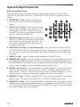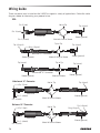
1
1000W STEREO POWERED MIXER
OWNER'S MANUAL
Owner's Manual
Copyright 2014
v1.2
Samson Technologies Corp.
45 Gilpin Avenue
Hauppauge, New York 11788-8816
Phone: 1-800-3-SAMSON (1-800-372-6766)
Fax: 631-784-2201
www.samsontech.com
FCC Notice
1. This device complies with Part 15 of the FCC Rules. Operation is subject to the following two conditions:
(1) This device may not cause harmful interference.
(2) This device must accept any interference received, including interference that may cause undesired operation.
2. Changes or modifications not expressly approved by the party responsible for compliance could void
the user’s authority to operate the equipment.
If you want to dispose this product, do not mix it with general household waste. There is a separate collection system for used electronic products in accordance with legislation that requires proper treatment,
recovery and recycling.
Private household in the 28 member states of the EU, in Switzerland and Norway may return their used electronic
products free of charge to designated collection facilities or to a retailer (if you purchase a similar new one).
For Countries not mentioned above, please contact your local authorities for a correct method of disposal.
By doing so you will ensure that your disposed product undergoes the necessary treatment, recovery and recycling
and thus prevent potential negative effects on the environment and human health.
Important Safety Information
This lightning flash with arrowhead symbol within an equilateral
triangle is intended to alert the user to the presence of noninsulated “dangerous voltage” within the product’s enclosure
that may be of sufficient magnitude to constitute a risk of
electric shock.
The exclamation point within an equilateral triangle is intended
to alert the user to the presence of important operating and
maintenance instructions in the literature accompanying the
appliance.
AVIS
RISQUE DE CHOC ÉLECTRONIQUE NE PAS OUVRIR
WARNING: TO REDUCE THE RISK OF ELECTRIC SHOCK, DO NOT REMOVE COVER (OR BACK) AS THERE ARE NO USERSERVICEABLE PARTS INSIDE. REFER SERVICING TO QUALIFIED SERVICE PERSONNEL.
1. Read these instructions.
2. Keep these instructions.
3. Heed all warnings.
4. Follow all instructions.
5. Do not use this apparatus near water.
6. Clean only with dry cloth.
7. Do not block any ventilation openings. Install in accordance with the manufacturer’s
instructions.
8. Do not install near any heat sources such
as radiators, heat registers, stoves, or other
apparatus (including amplifiers) that produce heat.
sold with the apparatus. When a cart is
used, use caution when moving the cart/
apparatus combination to avoid injury from
tip-over.
13. Unplug the apparatus during lightening
storms or when unused for long periods of
time.
14. Refer all servicing to qualified personnel.
Service is required when the apparatus has
been damaged in any way, such as power
supply cord or plug is damaged, liquid has
been spilled or objects have fallen into
the apparatus has been exposed to rain or
moisture, does not operate normally, or has
been dropped.
9. Do not defeat the safety purpose of the polarized or grounding type plug. A polarized
plug has two blades with one wider than the
other. A grounding type plug has two blades
and a third grounding prong. The wide
blade or the third prong are provided for
your safety. If the provided plug does not fit
into your outlet, consult an electrician for
replacement of the obsolete outlet.
15. This appliance shall not be exposed to dripping or splashing water and that no object
filled with liquid such as vases shall be
placed on the apparatus.
10. Protect the power cord from being walked
on or pinched particularly at the plugs,
convenience receptacles, and at the point
where they exit from the apparatus.
18. To prevent injury, this apparatus must be
securely attached to the stand in accordance with the installation instructions.
11. Only use attachments/accessories specified
by the manufacturer.
12. Use only with the cart, stand,
tripod, bracket, or table specified by the manufacturer, or
4
16. Caution-to prevent electrical shock, match
wide blade plug wide slot fully insert.
17. Please keep a good ventilation environment
around the entire unit.
19. WARNING: The battery (battery or batteries
or battery pack) shall not be exposed to
excessive heat such as sunshine, fire or the
like.
20. CAUTION: Danger of explosion if battery is
incorrectly replaced. Replace only with the
same or equivalent type.
Table of Contents
Introduction . . . . . . . . . . . . . . . . . . . . . . . . . . . . . . . . . . . . 6
S4000 Features . . . . . . . . . . . . . . . . . . . . . . . . . . . . . . . . . . 7
Quick Start . . . . . . . . . . . . . . . . . . . . . . . . . . . . . . . . . . . . 8
Basic Setup . . . . . . . . . . . . . . . . . . . . . . . . . . . 8
Adding Digital Effects . . . . . . . . . . . . . . . . . . . . . . 9
Sending a Mix to Monitor Speakers . . . . . . . . . . . . . . . . 10
Connecting a Subwoofer . . . . . . . . . . . . . . . . . . . . . 11
MP3 Player/Recorder . . . . . . . . . . . . . . . . . . . . . . . . . . . . . . . 12
Latching Cover . . . . . . . . . . . . . . . . . . . . . . . . . . . . . . . . . . 14
Controls and Functions . . . . . . . . . . . . . . . . . . . . . . . . . . . . . . . 15
Mono Input Channel Section . . . . . . . . . . . . . . . . . . . 15
Stereo Input Channel Section . . . . . . . . . . . . . . . . . . . 17
Digital Effects Section . . . . . . . . . . . . . . . . . . . . . . 19
Stereo Line Inputs . . . . . . . . . . . . . . . . . . . . . . . . 20
Master Auxiliary Send Section . . . . . . . . . . . . . . . . . . 20
PHONES and CD/TAPE MP3 IN Section . . . . . . . . . . . . . . 21
MONO/SUBWOOFER Output Section . . . . . . . . . . . . . . . 21
Main Output Section . . . . . . . . . . . . . . . . . . . . . . . 22
Power Amp Section . . . . . . . . . . . . . . . . . . . . . . . 23
Graphic Equalizer Section . . . . . . . . . . . . . . . . . . . . 24
Input and Output Connections . . . . . . . . . . . . . . . . . . . . . . . . . . . 25
Channel 1-12 Mono Mic/Line Inputs . . . . . . . . . . . . . . . 25
Channel 13-20 Stereo Input Channels . . . . . . . . . . . . . . 25
CD/TAPE IN and RECORD OUT . . . . . . . . . . . . . . . . . . 25
Master Input and Output Section . . . . . . . . . . . . . . . . . 26
Rear Panel Connections . . . . . . . . . . . . . . . . . . . . . 27
Speaker Connections . . . . . . . . . . . . . . . . . . . . . . . 27
Wiring Guide . . . . . . . . . . . . . . . . . . . . . . . . . . . . . . . . . . . 28
Specifications . . . . . . . . . . . . . . . . . . . . . . . . . . . . . . . . . . . 29
S4000 • Powered Mixer
5
Introduction
Congratulations on your purchase of the Samson S4000 powered mixer! The S4000 is a 20-channel, powered mixer in a tabletop enclosure. The mixer features a massive 2 x 500-watt stereo power
amplifier section and an integrated USB flash MP3 player/recorder.
To set the overall tonal response of your mix, the S4000 mixer features a nine-band Stereo Graphic
Equalizer for the Main Left and Right outputs, plus a separate Nine-band Graphic Equalizer for
your monitor mix. Connecting all your microphones and instruments is simple, with twelve mic/line
inputs plus four additional stereo channels.
To add depth to mix, you can add one of the mixer's 100 dazzling digital studio quality effects,
which include Delays, Chorus, Flanging, and of course, lush Reverbs to your vocals or instruments
using the onboard 24-bit Multi-Effects Processor. It’s easy to dial up your favorite effects preset
with the large seven-segment LED display. The mixer has extensive auxiliary buses allowing you
to have complex combinations of effects on all the channels, or two different effects on different
groups of channels. The auxiliary buses are also extremely flexible when it comes to monitor mixes.
The S4000 will give you clean, clear sound reproduction thanks to the high quality, low noise
microphone preamps, super clean, low impedance mix bus, and the high output/low distortion
power amplifier. The mixer is easy to transport with thanks to the oversized, sure-grip handle. The
S4000 includes a removable metal cover for added protection when transported and stored.
The super-tough steel construction ensures reliable, high quality sound from venue-to-venue and
performance-to-performance day in, and night out. The mixer is perfect for live sound reinforcement
and commercial installations, the S4000 is the ideal mixer and power amp solution that offer plenty of inputs, sweet sounding effects and big sound in a compact package.
We recommend you record your serial number in the space provided below for future reference.
Serial number: _________________________
Date of purchase: _______________________
With proper care and maintenance, your S4000 will operate trouble-free for many years. Should
your speaker ever require servicing, a Return Authorization (RA) number must be obtained before
shipping your unit to Samson. Without this number, the unit will not be accepted. Please call
Samson at 1-800-3SAMSON (1-800-372-6766) for an RA number prior to shipping your unit.
Please retain the original packing materials and, if possible, return the unit in its original carton. If
your S4000 was purchased outside of the United States, contact your local distributor for warranty
details and service information.
6
S4000 Features
The Samson S4000 powered mixer is a comprehensive, all-in-one mixer/power amplifier solutions
for a variety of live sound applications. Here are some of their main features:
• Massive 2 x 500-watts Stereo power amplifier section
• Twelve mic/line inputs plus four stereo line inputs, plus dedicated stereo returns for the onboard
effects.
• Two 24-bit digital effects processors, each with 100 selectable presets of studio quality effects
on each input.
• USB flash player/recorder to play back accompaniment or background music and record the
performance.
• High-quality, low-noise microphone preamplifiers that can accept signal from most standard microphones. With the mixer’s XLR connectors, connecting standard low impedance dynamic mics
is simple, and condenser microphones are connected easily using the available 48 Volt Phantom
Power.
• E
ach of the mic/line channels feature a convenient Insert Point jack to patch in external effects
and a three-band Equalizer with variable mid-range control enabling you to tailor the tonal response of each input.
• Four auxiliary sends. One dedicated Aux send for monitors, plus a second Aux send that can be
set up to be either a monitor send or an effects send using the Pre/Post switch, and two additional EFX sends for sending to the dual internal multi-effects processors.
• A Stereo 9-band Graphic Equalizer for the Main left and right outputs, plus a Mono 9-band for
the Monitor output, allow the mixer to be set-up for maximum gain before feedback.
• Mono/Subwoofer Output with variable Low-pass Filter.
• T
he brilliant sound quality is achieved thanks to the advanced circuit design, utilizing low-noise
operational amplifiers and low impedance busing.
• Durable steel enclosure is road tough insuring reliable performance from night to night and
venue to venue.
• Oversize grip handle and latching metal cover make the unit easy to transport and store.
S4000 • Powered Mixer
7
Quick Start
Basic Setup
The following section explains the basic setup and operation of the S4000.
1.
Before connecting mics or instruments, make sure that the power of all your systems components, including the S4000 mixer, is turned off. Also, make sure that the volume and gain
controls of each channel of the S4000 and the MAIN, MONO, AUX 1 and AUX 2 level faders
are turned all the way down.
2.
Make the connection to your speakers, using heavy gauge, unshielded speaker cable, from the
S4000 Speakon® or ¼" speaker outputs.
3.
Connect the cables to your microphones and instruments, and insert the other end of the cable
firmly into the appropriate inputs on the S4000.
4.
Switch on the power of any peripheral devices, and then power up the S4000.
NOTE: Since the S4000 contain two internal power amplifiers, it is important to remember the
Golden Rule of audio … "LAST ON, FIRST OFF". Translated, this means that when powering up
your PA system, you should always turn your power amplifiers on LAST, and when power your
system down, turn your power amps off FIRST. This helps avoid any loud pops caused by inrush current at power up or power down, which can sometimes damage loudspeakers.
5.
Make sure the channel faders are all down, then set the MAIN level fader control to the unity
or “0” position.
6.
Before you turn up a channel, you want to make sure you set a good level, with no distortion,
on the channel input GAIN. While speaking into the mic at performance level (or playing the
instrument), adjust the channel GAIN control so that the “PEAK” LED of the channel lights
occasionally, then back it down slightly.
7.
Once you have set the GAIN control, slowly adjust the channel LEVEL fader control until the
desired level is reached.
8.
If you wish to adjust the tone of each channel, adjust the equalizer controls as desired. You
may have to re-adjust the channel volume.
9.
Use the MAIN STEREO GRAPHIC EQ section graphic equalizer and MASTER control to adjust
the overall volume and tone. You can increase the overall level of your system by cutting certain frequencies that cause feedback.
8
Quick Start
Adding Digital Effects
The mixer features two built-in, high quality, 24-bit Multi Effect Processors, offering 100 studio grade effects presets. The EFX section features clean Delays, lush
Reverbs and multi-effects like Chorus + Delay or Chorus + Reverb. The following
details the operation of the internal DSP effects in the EFX section:
1. Connect a mic or instrument to the desired channel, adjust the level and
equalizer to your liking and make sure the MAIN fader level is set so you can
hear it in your speakers.
2. Press the EFX ON button to activate the digital effects channel strip.
3. Select the desired EFX program using the SELECT control knob located in the
middle of the EFX channel strip. Set the DSP SELECT switch to one of the
100 effects.
Note: Check the EFX Program List to find the effect perfect for your performance.
4. Set the EFX RTN fader control to the "0", unity position. The EFX RTN adjusts
the overall level of the digital effects to the MAIN MIX.
5. USE the EFX 1 control on each of the channels to adjust the level of signal to
sent to the effects.
6. If you want to hear the effects in the monitors, turn up the AUX1 RTN and/
or AUX2 RTN until you have the level of effects you want in those mixes. For
more information on setting up a monitor mix, see the following section.
NOTE: If the effect sound is distorted even though the EFX RTN is turned
down low, lower the EFX 1 controls of each channel.
7. Repeat the steps above for the second EFX section using the EXF 2 auxiliary
send.
S4000 • Powered Mixer
9
Quick Start
Sending a Mix to Monitor Speakers
The S4000 features two prefader auxiliary buses to create additional mixes of the input channels.
Follow these simple steps to set up an independent stage monitor mix.
1. Connect the AUX 1 Output to the input
of your monitor power amplifier. Connect
your amplifier to your monitor speakers
according the amplifier operating instructions.
2. Make sure that the AUX 1 Send level fader
is all the way down.
3. Raise the AUX 1 controls for the
channels that you wish to hear
from the monitor speakers.
NOTE: The monitor controls are
not affected by the level (fader) settings of each channel. This allows
you to create a mix for the monitor that is
independent of the MAIN mix.
1+ 11+ 2+
SX 1800
400 W
600 W
2+ 2-
E251753
23FY
1+ 1-
115V 60Hz, 1900W
4. Now raise the AUX 1 Send fader up until
you get a good level. If feedback occurs,
back down on the AUX 1 Send fader.
5. You can use the MONITOR GRAPHIC
EQUALIZER to cut the frequencies that
cause feedback. Setting the equalizer to
get the most gain before feedback requires
a good ear, but mostly, a lot of painful
experience. If you are just starting out use
the standard “smile” EQ curve where the
mids are cut down and the lows and high
are slightly boosted.
6. Use the graphic equalizer and AUX 1 Send fader level control in combination to adjust the overall volume and tone.
7. For a second monitor mix, repeat the steps above for using the AUX 2 monitor bus.
10
Quick Start
Connecting a Subwoofer
The S4000’s MONO OUT can be used to drive a subwoofer system by engaging
the SUBWOOFER ON/OFF switch located in the MONO output strip. When the
SUBWOOFER ON/OFF switch is pressed in, the variable Low Pass filter is active.
Use the FREQUENCY control knob to set the high frequency limit of the MONO/
SUBWOOFER OUT. The mixer’s FREQUENCY control has a range from 20Hz to
200Hz, allowing you to tune the output for your subwoofer.
Check your subwoofer’s owners manual for the manufacturers recommended cut
off frequency, or use your ears while slowly sweeping the cut off point using the
FREQUENCY control knob to find the correct setting for your system.
1+ 11+ 2+
SX 1800
400 W
600 W
2+ 2-
E251753
23FY
1+ 1-
115V 60Hz, 1900W
S4000 • Powered Mixer
11
MP3 Player/Recorder
A
B
D
C
E
F
The S4000 features a USB flash MP3 player/recorder. This allows you to fly-in prerecorded audio or
to quickly record the current mix to the Main Mix. The MP3 playback level is controlled via the CD/
TAPE MP3 fader.
Controls
A. Previous - Press to select the previous song or select the previous menu
B. Next - Press to select the next song or select the next menu
C. Return - Press to return to the previous menu
D. Repeat - Press to set the play mode while a song is playing:
Repeat 1, Repeat All, Random (shuffle) play, View Playing, Repeat All random play, View Playing
Random Play, Order of Play.
E. REC - Press to select Recording Menu
F. Play/Pause POWER - Press to play or pause a song. When in a menu press to enter or confirm
selection. Press and hold for 3 seconds to turn the power on or off.
Operation
Press and hold the Power button for three seconds, the main menu will be shown on the display.
Press the Previous or Next buttons to select between the menus: Set, Music, and Recordings.
Set (Settings)
Select “Set” and press the Play/Pause button to enter the Set menu. In the Set menu you can select
the Play mode and select the Language.
Play mode
Select and enter “Play mode.” It will show the “Repeat” and “Shuffle”
Repeat
Enter “Repeat” by pressing the Play/Pause button. There are four available play modes: Repeat
Off, Repeat 1, Repeat all and, View playing. Press the Previous or Next buttons to select between
the four choices. Press the Play/Pause button to confirm the selected play mode.
Shuffle (Random Play)
Enter “Shuffle” by pressing the Play/Pause button.
Note: While a song is playing, you can press the Repeat button to quickly select the play mode.
12
MP3 Player/Recorder
Language
Enter “Language” by pressing the Play/Pause button. Press the Previous or Next buttons to cycle through available languages. Press the Play/Pause button to confirm the selected language.
Press the Return to return to the previous menu.
Music
Select “Music” and press the Play/Pause button to enter the Music menu. In the Music menu you
can go view and select files on the USB thumb drive.
U-disk
Press the Play/Pause button to select the U-disk Dir. In the U-disk Dir you can view all the
songs and documents in the USB drive.
Press the Previous or Next buttons to select the song, then press the Play/Pause button to play
the song. While a song is playing, press the Play/Pause button to pause, press Play/Pause button again to continue playing the song.
Press the Previous button to select previous song, or press the Next button to select the next
song.
Press Return button to return to the previous menu.
Recordings
Select “Recordings” and press Play/Pause button to enter the Recordings menu. You can also press
the REC button to quickly access the Recordings menu. In the Recording menu you can start a recording and view all recorded files on the USB thumb drive.
Start Voice Recording
Press the Previous or Next buttons to select ‘Start Voice Recording’.
Press the Play/Pause button start recording. Press the Play/Pause button again to pause the
recording. Press the Play/Pause button to continue recording.
When you have finished recording, press the Return button to save or delete the file. Press the
Play/Pause button to save the recording. Press the Return key to delete the recording and return
to U-disk driver.
-Press the Play/Pause button to enter U-disk. In the U-Disk menu, you can view the recorded
files.
Recordings Library
Press Previous or Next buttons to select ‘Recordings Library’. Press the Play/Pause button to
enter U-disk.
In the U-disk menu, you can select “Delete All” to delete all recordings; select recording to
play; press Previous or Next buttons to select one recordings and press Play/Pause button to play
the selected file.
Caution: If you select Delete All, all of the recordings in the directory will be deleted.
Press the Return button to return to the previous menu.
S4000 • Powered Mixer
13
Latching Cover
Follow these instructions to remove the protective cover:
1. Unlock the two latches on the rear panel of the mixer.
2. Lift the lift off of the mixer.
3. Slide the cover to left to detach the cover from the hinges.
14
Controls and Functions
Mono Input Channel Section
The following section details each part of the twelve mono input channels.
1. SIGNAL LED - MIC/LINE preamp SIGNAL LED which, when illuminated,
indicates that the signal is present at the input.
1
2
3
2. GAIN Control Knob - Variable GAIN control with a range of -6 to -50dB
on the MIC input and +14 to -30dB on the LINE input.
3. LOW CUT Switch - LOW CUT (or high pass) filter rolls off the low frequencies from 75Hz and below at the rate of 18dB per octave.
4. Channel Equalizer - 3-band, swept-mid equalizer allowing you to adjust
the high, mid-range, and low frequencies independently on each channel. The frequency centers, range of boost or cut, and equalizer type
for each band are described in the following section.
HF (HIGH FREQUENCY) 12kHz +/- 15dB Shelving type - The channel’s
high frequency response is flat when the knob is in the “12:00” position. Rotating the knob towards the right will boost the channel's high
frequency response at 12 kHz by 15dB, and rotating it towards the left
will cut the high frequency by 15dB.
MF (MID FREQUENCY) CUT & BOOST - The mid cut & boost knob is used
in conjunction with the FREQ knob to create the tonal shape in the
mid-range frequency when using the mono channel’s equalizers. You
can adjust the frequency on the mid-range control with the FREQ
knob, and use the MF knob to either boost or cut that frequency by
plus or minus 15dB. The channel’s mid frequency response is flat
when the MF knob is in the “12:00” position.
FREQ (MID FREQUENCY) Variable 100Hz – 8K - The mid FREQ is a control enabling you enhanced capabilities in the tonal shaping of the
input channel signal. Thanks to the FREQ control, you have a variable
mid-range equalizer, allowing you to pin point the exact frequency
you want to boost or cut. The FREQ has a “fixed Q” of two octaves
(the amount, or width, of frequencies around the center point that are
effected by the MF control) and can be set in a range from 100Hz to
8Khz.
LF (LOW FREQUENCY) 80Hz +/- 15dB shelving type - The channel’s low
frequency response is flat when the knob is in the “12:00” position.
Rotating the knob towards the right will boost the channel's low frequency response at 80 Hertz by 15dB, and rotating it towards the left
will cut the frequency by 15dB.
4
5
6
7
8
9
10
11
13
12
14
5. AUX 1 (Pre Fader Send) - Controls the amount of that channel’s signal
that is sent to the AUX 1 Output. The signal feeding Aux 1 is sent
before, or pre, the channel Fader, so the channel Fader has no effect
on the Aux 1 level. The Aux 1 is usually used to create a separate mix
for a floor monitor system.
S4000 • Powered Mixer
15
Controls and Functions
6. AUX 2 (PRE/POST) - Controls the amount of that channel’s signal that is sent to the AUX 2
Output. The signal that feeds Aux 2 is sent before, or pre, the channel Fader, so the channel
Fader has no effect on the Aux 2 level. On the S4000, Aux 2 can be configured for pre or post
fader send using the PRE/POST switch. The Aux 2 bus is usually used to create a separate mix
for a floor monitor system, but you can set the Pre/Post switch on the S4000 to Post to use the
send as an effects bus to an external processor.
7. POST (Pre/Post) Switch - The POST switch is used to select the point that the Aux 2 bus uses to
send the signal. When the POST switch is in the up (PRE) position, the signal feeding Aux 2 is
sent before the fader, so the channel Fader has no effect on that level. This is the normal setting when using Aux 2 as a monitor send. When the POST switch is in the down (POST) position, the signal feeding Aux 2 is sent after the fader, so the channel Fader has an effect on that
level, meaning the Aux level tracks up and down with the channel Fader. This is the normal
setting for using Aux 2 as an effects send, since when you set the channel louder you normally
want the effect to get louder.
8. AUX 3/EFX1 (Post Fader Effects Send) - The S4000 provides high quality, 24 Bit digital effects,
and the level of effects can be set independently on each channel. The channel’s EFX knob
controls the amount of signal that is sent to the EFX bus. The signal of the EFX bus is routed
to the DSP EFX section for on-board signal processing. The EFX1 signal can also be sent to an
external effect device connected to the EFX 1 SEND jack located on the front panel jack field.
9. AUX 4/EFX 2 (Post Fader Effects Send) - The channel’s EFX (Effects) knob controls the amount of
signal that is sent to the EFX bus. The signal of the EFX bus is routed to the DSP EFX section
for on-board signal processing. The EFX2 signal can also be sent to an external effect device
connected to the EFX 2 SEND jack located on the front panel jack field.
NOTE: The signal feeding EFX1 and EFX2 is sent after the channel Fader, so the channel Fader
has an effect on that level, meaning the Aux level tracks up and down with the channel Fader.
10. PAN Control - The PAN control is used to place or position the mono signal into the stereo main
Left and Right MIX bus. You can create a stereo image by panning some input signals to the
left and others to the right.
11. MUTE switch - The mono Input channels feature a large, backlit MUTE switch allowing you to
easily turn the channel's audio on or off. When MUTE switch is illuminated, the channel is off,
conversely, when the back-light is off, the channel is on.
12. PFL (Pre Fader Listen) switch - The Mono Input channel’s PFL, or Pre Fader Listen switch allows
you to listen, or “solo” a channel or group of channels in the headphones. When the PFL switch
is pressed down, the channel is assigned to the solo bus and can be heard in headphones
plugged in to the PHONES connector located in the front panel jack field. Since the signal is
sent pre fader, you can hear the signal regardless of the position of the channel volume Fader.
This allows you to listen to a channel by itself without having to play it through the main PA
speakers.
13. PEAK LED - The S4000’s MIC/LINE preamp includes a PEAK LED which when illuminated, indicates that the signal is peaking or overloading. To reduce distortion, lower the GAIN control to
keep this LED from staying on.
14. VOLUME Fader - The VOLUME Fader control adjusts the level of each mono input channel.
16
Controls and Functions
Stereo Input Channel Section
The S4000 feature stereo input channels for connected stereo line
level devices like keyboards and drum machines, as well as the outputs
from effects processors and digital guitar modelers.
15
16
15. SIGNAL LED - The SIGNAL LED which, when illuminated, indicates
that a signal is present at the input.
16. GAIN Control - The preamp stage has a variable GAIN control with
a range of -20 to +20dB on the stereo LINE input.
17. Channel Equalizer - 3-band equalizer allows you to adjust the high,
mid-range, and low frequencies independently on each channel.
HF (HIGH FREQUENCY) 12kHz +/- 15dB Shelving type - The channel’s
high frequency response is flat when the knob is in the “12:00”
position. Rotating the knob towards the right will boost the channel's high frequency response at 12 kHz by 15dB, and rotating it
towards the left will cut the high frequency by 15dB.
MF (MID FREQUENCY) 2.5kHz +/- 15dB peaking type - The MF knob
is used to create the tonal shape in the mid-range frequency when
using the stereo channel’s equalizers. You can use the MF knob to
either boost or cut 2.5kHz frequency by plus or minus 15dB. The
channel’s mid frequency response is flat when the MF knob is in
the “12:00” position.
17
18
19
20
LF (LOW FREQUENCY) 80Hz +/- 15dB shelving type - The channel’s
low frequency response is flat when the knob is in the “12:00”
position. Rotating the knob towards the right will boost the channel's low frequency response at 80 Hertz by 15dB, and rotating it
towards the left will cut the frequency by 15dB.
21
18. AUX 1 (Pre Fader Send) - Controls the amount of that channel’s signal that is sent to the AUX 1 Output. The signal feeding Aux 1 is
sent before, or pre, the channel Fader, so the channel Fader has
no effect on the Aux 1 level. The Aux 1 bus is usually used to create a separate mix for a floor monitor system.
23
19. AUX 2 (PRE/POST) - Controls the amount of that channel’s signal
that is sent to the AUX 2 Output. The signal that feeds Aux 2 is
sent before, or pre, the channel Fader, so the channel Fader has
no effect on the Aux 2 level. On the S4000, Aux 2 can be configured for pre or post fader send using the PRE/POST switch. The
Aux 2 bus is usually used to create a separate mix for a floor monitor system, but you can set the Pre/Post switch on the S4000 to
Post to use the send as en effects bus to an external processor.
22
24
26
25
27
20. POST (Pre/Post) Switch - The POST switch is used to select the
point that the Aux 2 bus uses to send the signal. When the POST
switch is in the up (PRE) position, the signal feeding Aux 2 is sent
before the fader, so the channel Fader has no effect on that level.
This is the normal setting when using Aux 2 as a monitor send.
S4000 • Powered Mixer
17
Controls and Functions
When the POST switch is in the down (POST) position, the signal feeding Aux 2 is sent after
the fader, so the channel Fader has an effect on that level, meaning the Aux level tracks up
and down with the channel Fader. This is the normal setting for using Aux 2 as an effects send,
since when you set the channel louder you normally want the effect to get louder.
21. AUX 3/EFX 1 (Post Effects Fader Send) - The S4000 provides high quality, 24 Bit digital effects,
and the level of effects can be set independently on each channel. The channel’s EFX knob
controls the amount of signal that is sent to the EFX bus. The signal of the EFX bus is routed to
the DSP EFX section for on-board signal processing. On the S4000 the EFX1 signal can also be
sent to an external effect device connected to the EFX 1 SEND jack located on the front panel
jack field.
22. AUX 4/EFX 2 (Post Effects Fader Send) - The channel’s EFX (Effects) knob controls the amount of
signal that is sent to the EFX bus. The signal of the EFX bus is routed to the DSP EFX section
for on-board signal processing. The EFX2 signal can also be sent to an external effect device
connected to the EFX 2 SEND jack located on the front panel jack field.
NOTE: The signal feeding EFX1 and EFX2 is sent after the channel Fader, so the channel Fader
has an effect on that level, meaning the Aux level tracks up and down with the channel Fader.
23. BALANCE Control - This control is used to place, or position, the stereo signal into the main Left
and Right stereo mix field. You can create a stereo image by panning some input signals to the
left and others to the right.
24. MUTE switch - The stereo Input channels feature a large, backlit MUTE switch allowing you to
easily turn the channel's audio on or off. When MUTE switch is illuminated, the channel is off,
conversely, when the back-light is off, the channel is on.
25. PFL (Pre Fader Listen) switch - The channel’s PFL, or Pre Fader Listen switch allows you to listen,
or “solo” a channel or group of channels in the headphones. When the PFL switch is pressed
down, the channel is assigned to the solo bus and can be heard in headphones plugged in to
the PHONES connector located in the front panel jack field. Since the signal is sent pre fader,
you can hear the signal regardless of the position of the channel volume Fader. This allows you
to listen to a channel by itself without having to play it through the main PA speakers.
26. PEAK LED - The preamp includes a PEAK LED which when illuminated, indicates that the signal
is peaking or overloading. To reduce distortion, lower the GAIN control to keep this LED from
staying on.
27. VOLUME Fader - The VOLUME Fader control adjusts the level of each mono input channel.
18
Controls and Functions
Digital Effects Section
The S4000 feature built-in, 24 Bit Digital Multi-effects Processors with 100 dazzling, studio quality effects like Delay, Chorus, Flanger and lush Reverbs including Halls, Plates and Rooms. The
following section describes the features control knobs and layout of the
powerful on-board digital Multi-effects section.
28. Program Effects Display - The mixer's multi-effects processors feature
a dual digit, seven-segment numerical Effects Display for showing
the effects PROGRAM number from 00 - 99. When the Effects Display shows two straight lines through the center of each segment the
effects are turned off.
28
29. SELECT Control Knob - The SELECT control knob is a continuously variable encoder to call up one of the 100 built-in digital effects presets.
Rotate the SELECT knob to scroll through the preset programs and
press to load the selected effect.
30. EFX ON Switch - The EFX ON switch is used to turn the internal Digital
Effect on and off. The effects are by-passed when the switch is in the
out position and the Effects Display shows two dashes.
31. TO AUX 1 (Effects Return to Aux 1) - This control is used to adjust the
level of the effects from the built-in digital effect that is sent to the
Aux 1 monitor bus. This allows you to add the DSP effects to the signal in your monitor speakers.
32. TO AUX 2 (Effects Return to Aux 2) - This control is used to adjust the
level of the effects from the built-in digital effect that is sent to the
Aux 2 monitor bus. This allows you to add the DSP effects to the signal in your monitor speakers.
33. SEND (Master Effect Send) - The master EFX SEND control is used to
send the effect mix bus to an external effect device connected to the
EFX OUT SEND jack.
29
30
31
32
33
34. Effects Return PFL Switch (Pre Fader Listen) - The PFL, or Pre Fader Listen switch allows you to listen, or “solo” the EFX Return in the headphones. Since the signal is sent pre fader, you can hear the signal
regardless of the position of the EXF RTN volume Fader. This allows
you to listen a EFX RTN 1 by itself: to see if a reverb is long enough,
or to cue up an echo without having to play it through the main PA.
34
35. EFX RTN FADER (Effects Level Control) - The EFX RTN fader control is
used to adjust the level of the effects from the built-in digital effect
that is sent to the MAIN mix bus. This allows you to hear the DSP
effects in your MAIN speakers.
35
S4000 • Powered Mixer
19
Controls and Functions
Stereo Line Inputs
36. AUX 1 (Pre Fader Send) - Controls the amount of that channel’s signal
that is sent to the AUX 1 Output. The signal feeding Aux 1 is sent
before, or pre, the channel Fader, so the channel Fader has no
effect on the Aux 1 level. The Aux 1 bus is usually used to create
a separate mix for a floor monitor system.
37. AUX 2 (Pre Fader Send) - Controls the amount of that channel’s signal
that is sent to the AUX 2 Output. The signal feeding Aux 2 is sent
before, or pre, the channel Fader, so the channel Fader has no
effect on the Aux 2 level. The Aux 2 bus is usually used to create
a separate mix for a floor monitor system.
38. LEVEL Control Knob -The Level control adjusts the level of each
mono/stereo input channel.
39. PFL (Pre Fader Listen) switch - The channel’s PFL, or Pre Fader
Listen switch allows you to listen, or “solo” a channel or group
of channels in the headphones. When the PFL switch is pressed
down, the channel is assigned to the solo bus and can be heard in
headphones plugged in to the PHONES connector located in the
front panel jack field. Since the signal is sent pre fader, you can
hear the signal regardless of the position of the channel volume
Fader. This allows you to listen to a channel by itself without having to play it through the main PA speakers.
36
37
38
39
40
41
Master Auxiliary Send Section
40. AFL (After Fader Listen) Switch 1 &2 - The Aux 1 & 2 master send output’s AFL, or After Fader
Listen switch allows you to listen, or “solo” a channel or group of channels in the headphones.
When the AFL switch is pressed down, that Aux’s signal is assigned to the solo bus and can be
heard in any optional headphones plugged in to the PHONES connector located in the front
panel jack field. This allows you to listen to an Aux send by itself to check that a signal is not
distorted before it gets to the power amplifier. Since the signal is sent after the Aux 1 level
fader, you hear the signal with the added gain from the Aux 1 Level control.
41. AUX 1 & 2 Master Send Faders - These faders control the overall output of the Aux 1 & 2 bus.
Each of the channels Aux signals are mixed together and sent to the Aux Outputs. Use the Aux
1 & 2 level controls to set the amount of signal being sent to Aux 1 & 2 Outputs.
20
Controls and Functions
PHONES and CD/TAPE MP3 IN Section
42. PHONES Control knob - This control adjusts the level of Headphone Output.
43. MAIN MIX 2 Control Knob - The mixer provides a second set of output connectors carrying a duplicate of the MAIN MIX signal for the purpose of feeding
another speaker zone or recorder. The MAIN MIX 2 control knob is used to set
the volume of the MAIN Mix 2 output.
44. Mute CH 1-12 Switch - This switch mutes input channels 1-12. This is especially convenient when you take a break and want to leave all the levels set so
they are ready when you begin to use your PA system again. The MUTE switch
features an electronic circuit for silent switching that ramps the signal up and
down to prevent pops when the switch is turned on and off.
45. PFL Switch - The CD/TAPE MP3 input channel’s PFL, or Pre Fader Listen
switch allows you to listen, or “solo” the CD/TAPE MP3 input in the headphones. When the CD/TAPE MP3 input channel’s PFL switch is pressed
down, that channel’s signal is assigned to the solo bus and can be heard in
any optional headphones plugged in to the PHONES connector located in
the front panel jack field. Since the signal is sent pre fader, you can hear the
signal regardless of the position of the channel Level control. This allows you
to listen to a channel by itself to cue up a song on a CD player without having
to play it through the main PA speakers.
47
48
49
42
43
44
45
46
46. CD/TAPE MP3 Fader - The S4000 has a dedicated line level
CD/TAPE MP3 input to connect a CD, Tape or MP3 player.
The CD/TAPE MP3 level fader control is used to adjust the
volume of the signal connected to the CD/TAPE MP3 input.
MONO/SUBWOOFER Output Section
The S4000 has a MONO output that can be used to send to a secondary speaker
zone. You can also configure the MONO Output to drive a subwoofer system by
using the built-in variable Low Pass Filter.
47. FREQUENCY Control Knob - Use the FREQUENCY control to adjust the crossover point for the Low Pass Filter in a range of 20 Hz to 200 Hz when the
MONO/SUB OUT is connected to a subwoofer. The FREQUENCY control
knob is active when the SUBWOOFER ON/OFF switch is set to ON.
48. SUBWOOFER ON/OFF Switch - Used to engage the Low Pass Filter and turn the
MONO output into a subwoofer output.
50
49. AFL (After Fader Listen) Switch - The MONO output’s AFL, or After Fader
Listen, switch allows you to listen, or “solo” the MONO in the headphones.
When the MONO AFL switch is pressed down, the left/right mix will be
heard in any optional headphones plugged in to the PHONES connector
located in the front panel jack field. Since the signal is sent after the MONO
level fader, you hear the signal with the added gain from the MONO Level
control
50. MONO Level fader - The MONO level fader control is used to adjust the volume of the signal connected to the MONO/SUB output.
S4000 • Powered Mixer
21
Controls and Functions
Main Output Section
51. PEAK Indicators - The left and right PEAK indicators illuminate when the signal from the MAIN mix is beginning to reach a level where distortion occurs.
If the PEAK lights stay on, your mix is too "hot" and you need to lower the
MAIN mix volume. It is okay for the PEAK light to occasionally light, however they should go off quickly and not stay on.
51
52
52. Output Level Meter - The output level meter allows you to monitor the level of
the signal, which is being sent to the MIX OUT jacks.
NOTE: To avoid distortion, adjust the MAIN level control so that the 0 indicator LED lights occasionally.
53. AFL (MAIN MIX) Switch - The MAIN MIX output’s AFL, or After Fader Listen,
switch allows you to listen, or “solo” the MAIN MIX in the headphones.
When the MAIN MIX AFL switch is pressed down, the left/right mix will be
heard in any optional headphones plugged in to the PHONES connector located in the front panel jack field. This allows you to listen to the stereo mix
to check that a signal is not distorted before it gets to the power amplifier.
Since the signal is sent after the MAIN MIX level fader, you hear the signal
with the added gain from the MAIN MIX Level control.
54. MAIN MIX (left and right) Level Fader - The MAIN MIX Level fader adjusts the
level of MAIN left and right stereo mix.
22
53
54
Controls and Functions
Power Amp Section
The S4000’s power amplifier section includes the PEAK limiter and Phantom Power switch, as well
as LED indicators for the Protection Circuit. The PHANTOM POWER switch engages the power supply to allow you to connect condenser microphones. The PEAK LIMITER helps you keep the sound
clean by using an active circuit to automatically control the system dynamics. And the Protection
Circuit will help your S4000 run trouble free for years.
55. PROTECT Indicators -The S4000 mixer has a protection circuit to help
prevent damage to the power amplifiers when it is presented with a
clipped signal for an unsafe duration. The PROTECT indicators will illuminate when the protection circuit is active to help avoid serious damage to the amplifier section. There are individual PROTECT indicators
for the left and right power amplifiers. If either of the PROTECT indicators illuminate, turn the main volume down and wait for the LED to go
off. In order to keep the amplifier from going into PROTECT mode, be
sure to keep the PEAK LEDS in the MAIN meter section from lighting.
55
56
57
56. PEAK LIMITER Switch and Indicator - In order to keep the sound loud and clean, there is an onboard Limiter which is a dynamic processor that helps keep the signal from clipping the power
amplifier. When you press the PEAK LIMITER switch in, the red LED will illuminate indicating
that the dynamics processing is engaged.
IMPORTANT NOTE: Unless you are using an external limiter, it is highly recommended that the
LIMITER switch be engaged at all times. This will ensure the cleanest possible output, and
will protect your speaker system when it accidentally receives a clipped signal from your mixer.
57. Phantom Power Switch and Indicator - The mixer features an onboard, 48-Volt Phantom power
supply to operate condenser microphones. When the switch is engaged, the LED will illuminate indicating that phantom power is now available at the microphone preamps.
IMPORTANT NOTE: To avoid a loud pop, be sure to turn down the master level controls before
plugging and unplugging the mic cables when the phantom power is active. Be sure the MAIN
level fader is turned all the way down before activating the Phantom Power to prevent pops
from entering any external device connected to the mixer. Also, be sure the Phantom Power is
OFF when connecting or disconnecting microphones.
S4000 • Powered Mixer
23
Controls and Functions
Graphic Equalizer Section
57. MONITOR EQUALIZER - This nine-band MON57
ITOR EQUALIZER allows you to contour the
58
frequency response of the AUX 1 mix bus
signal. Providing a maximum of 12dB of cut/
boost for each frequency band, the Graphic
EQ is also extremely useful tool for cutting the
frequencies that cause annoying feedback. The
frequency response is flat when the sliders are 59
60
in the center position. Moving a slider in the
positive direction will boost that frequency by
as much as 12dB, and moving the slider in
the negative direction will cut that frequency by up to 12dB. The response curve set using the
Graphic Equalizer is also applied to the signal at the AUX 1 output.
58. MONITOR EQ ON/OFF Switch - The EQ ON/OFF switch is used to engage or bypass the MONITOR
EQUALIZER. When the switch is in the down position, the EQ is on and when the switch is up,
the EQ is bypassed.
59. MAIN STEREO EQUALIZER - This nine-band MAIN STEREO EQUALIZER allows you to contour
the frequency response of the MAIN stereo mix bus signal. Providing a maximum of 12dB of
cut/boost for each frequency band, the Graphic EQ is also extremely useful tool for cutting the
frequencies that cause annoying feedback. The frequency response is flat when the sliders are
in the center position. Moving a slider in the positive direction will boost that frequency by as
much as 12dB, and moving the slider in the negative direction will cut that frequency by up to
12dB. And since the MAIN Graphic Equalizer is stereo, the EQ curve is applied to both the left
and right signal at the internal power amp input, the MAIN MIX out, MAIN INSERT, as well as
the MAIN MIX OUT 2 output.
60. MAIN EQ ON/OFF Switch - The EQ ON/OFF switch is used to engage or bypass the MAIN EQUALIZER. When the switch is in the down position, the EQ is on and when the switch is up, the EQ
is bypassed.
24
Input and Output Connections
The S4000 mixer has 20 mono mic/line and stereo line input channels, for connecting a variety
of signal sources from microphones to line level devices such as synthesizers, drum machines and
direct boxes.
Channel 1-12 Mono Mic/Line Inputs
The mono mic/line inputs each have a LINE level input, a MIC level input and an Insert connector
for effects.
A. MIC (Microphone) Input - Use these inputs to connect Low Impedance microphones and low-level signals from direct boxes. The MIC inputs have a nominal operating level of –50dBV through -20dBV. The MIC inputs also feature
+48V phantom power, allowing you to use condenser microphones. The
Phantom Power is switched on/off simultaneously for channels 1 through 12.
A
B
B. LINE (Line Level) Input - Use these inputs to connect high impedance microphones, synthesizers and drum machines. The LINE inputs have a nominal
C
operating level of -40dBV through - 10dBV.
NOTE: It is not possible to simultaneously use both the LINE and MIC inputs
on the same channel. For each channel, use only one of the inputs as appropriate for the
input source.
C. INSERT (Send and Return) jack - The S4000 have a ¼", TRS (TIP/RING/SLEEVE) Insert jack
for connecting outboard effects processors directly on the channel input. The signal is sent
on the tip (the Send) and returns on the ring (the Return) of the connector.
Channel 13-20 Stereo Input Channels
The stereo input channels are used for connecting stereo signals like those from CD or MP3
players, electronic keyboards, drum machines and other line level signals.
D
D. Stereo Inputs (RCA jacks) - The stereo channel's RCA
connectors accept signals from stereo line devices. The
RCA line level inputs have a nominal operating level of
-40dBV through - 10dBV.
E. Stereo Inputs (¼" jacks) - Use the ¼" jacks for connecting stereo line level sources. For stereo inputs use the
LINE L to connect the left channel and the LINE R to
connect the right channel. Use these inputs to connect
high impedance microphones, synthesizers and drum
machines. The LINE inputs have a nominal operating
level of -40dBV through - 10dBV.
F
G
E
CD/TAPE IN and RECORD OUT
You can interface a digital recorder, computer sound card or other recorders using the S4000’s
CD/TAPE and RECORD OUT.
F. CD/TAPE Inputs (RCA jacks) - Stereo line level input, on RCA connectors, for connecting the
output of devices such as MP3, CD, computer sound-card, or any other line level device.
G. Record Out (RCA jacks) - The signal present at this connector is the MAIN bus signal before
it has passed through the MASTER level control and graphic equalizer. The nominal output
level is -10dBV and the impedance is 100 Ohms.
S4000 • Powered Mixer
25
Input and Output Connections
Master Input and Output Section
The mixer's Master Input and Output section has the connectors for interfacing the PHONES,
FOOTSWITCH, MAIN OUT, MAIN OUT 2, MAIN INSERT POINTS, AMP IN, and the master AUX
outputs.
H. FOOTSWITCH (¼" jack) - Connect a footswitch to
this jack to turn on and off the on-board digital
effects.
I. EFX OUT 1 & 2 (¼" jack) - These outputs are used
to send signals to external signal processors. The
signal present at the EFX 1 output is sent from
the AUX 3 bus, and the signal preset at the EFX 2
output is sent from the AUX 4 bus.
J. AMP IN Left & Right (¼" jacks) -The Left and Right
AMP IN ¼" phone jacks are used to make a direct
connection to the internal power amplifiers. You
can connect a stereo source like the output from
an external mixer here.
J
K
L
H
M
I
N
P
K. MAIN INSERT Left & Right (¼" Send and Return jack) - Send and return patch point on TRS
(TIP/RING/SLEEVE) jack for interfacing external effects processors on Left and Right MIX
bus. The signal is sent on the tip (the Send) and returns (the Return) on the sleeve of the
connector.
L. PHONES (¼" jack) - Connect standard stereo headphones, 60 to 600 Ohms.
M. MONO/SUB OUT (¼" jack) - The Left and Right Mix outputs are summed together and sent to
the unbalanced MONO/SUB output. The volume of the Mono signal can be adjusted using
the MONO/SUB OUT level fader control. For added flexibility, the MONO/SUB OUT can be
used to a feed a subwoofer using the onboard variable Low Pass Filter.
N. AUX OUT 1 & 2 (¼" jacks) - The signal present at the AUX 1and Aux 2 outputs are sent from
the AUX 1 and AUX 2 bus, which is fed from the AUX 1 and AUX 2 control knobs on the
input channels. The AUX 1 and AUX 2 are normally used as a MONITOR MIX bus in a live
sound situation by connecting the output to a power amp and monitor speaker.
O. MAIN OUT (¼" jacks) - These line level MAIN OUT jacks can be connected to drive a second
speaker system. The signal at the MAIN OUT jacks follows the MAIN volume fader.
P. MAIN OUT 2 (¼" jacks) - These line level MAIN OUT 2 outputs can be used to drive a second
speaker system or connect to a stereo device such as computer sound card, MP3, or recorder. The signal at the MAIN OUT 2 jacks follows the MAIN OUT 2 level control knob allowing
you to set a different level to the recorder.
26
Input and Output Connections
Rear Panel Connections
Q. AMP 1 Powered Speaker Outputs - The AMP 1 output has a ¼" jack and a Speakon connector, which
are powered outputs used to connect your left side
main PA speakers.
R. AMP 2 Powered Speaker Outputs - The AMP 2 output
has ¼" jack and a Speakon connector, which are
powered outputs used to connect your right side
main PA speakers.
R
Q
Speaker Connections
The S4000 contain two mono power amplifiers which deliver a maximum output of 500W + 500W.
The total impedance load for each amplifier must not be less than 4 Ohms.
If you use a single speaker to the ¼" jack or Speakon connector, use a 4 through 8 Ohm speaker.
The total impedance load for each amplifier must not be less than 4 Ohms, therefore one speaker
with an impedance of 4 ohms can be connected to each amp’s ¼" jack or Speakon connector (see
figure 1).
Two 8 Ohm speakers can be connected to the AMP 1 ¼" jack and Speakon connectors simultaneously and two more to the AMP 2 ¼" jack and Speakon connectors, for a total of four speakers. The
A/B jacks are wired in "Parallel", so the total impedance when two 8 Ohm speakers are connected is
4 Ohms (see figure 2).
figure 1
figure 2
Not Connected
Speakon® wiring
S4000 • Powered Mixer
27
Wiring Guide
There are several ways to interface the S4000 to support a variety of applications. Follow the cable
diagrams below for connecting your powered mixer.
RCA
Pin 2 (hot)
Hot to Tip
Tip (signal)
Pin 3 (cold)
Male XLR
Shield & Cold to Sleeve
Pin 1 (shield)
Tip to Tip
Tip (+Signal)
Ring (-Signal)
Sleeve (ground)
Tip (signal)
Balanced ¼” Connector
Sleeve (ground)
Sleeve & Ring to Sleeve
Tip (signal)
Tip to Tip
Sleeve (ground)
Tip (signal)
Unbalanced ¼” Connector
Sleeve (ground)
Unbalanced ¼” Connector
Pin 2 (hot)
Male XLR
Pin 1 (shield)
Pin 3 (cold)
Balanced ¼” Connector
Pin 2 (hot)
Sleeve to Sleeve
Hot to Tip
28
Tip (signal)
Sleeve (ground)
Shield & Cold to Sleeve
Hot to Tip
Male XLR
Pin 1 (shield)
Pin 3 (cold)
Sleeve (ground)
Tip (+Signal)
Ring (-Signal)
Sleeve (ground)
Shield & Cold to Sleeve
Specifications
Rated Output power
2 X 500W at 4Ω @0.1% THD at 1KHz
Frequency response20Hz~20KHz+/-0.7dB@1W Output into 8Ω (AMP OUT)
20 Hz~20KHz+/-0.4@+4dB Output into 10kΩ (MAIN OUT, AUX OUT,
AUX SEND, EFX OUT)
Total Harmonic DistortionLess than 0.06%@20Hz~20KHz, 75W output into4Ω (AMP OUT)
Less than 0.1%@20 Hz~20KHz+14dB output into 10KΩ (MAIN OUT,
AUX OUT, AUX SEND, EFX OUT)
(Average,RS+150Ω)
HUM & Noise -124dB equivalent input noise
(with 22Hz~22KHz BPF)-100dB residual output noise (MAIN OUT, MONITOR OUT, EFX OUT)
-70dB (MAIN OUT, AUX OUT) Master level control at maximum, all
channel level control at minimum.
-70dB (EFX OUT) Master level control at maximum, all channel level
controls at minimum
Maximum Voltage Gain99dB CH IN (MIC) to AMP OUT
74dB CH IN (MIC) to MAIN OUT, MONITOR OUT
70dB CH IN (MIC) to AUX 2 OUT
52.2dB CH IN (MIC) to REC OUT
54dB CH IN (LINE) to MAIN OUT, MONITOR OUT
16dB AUX IN to MAIN OUT
24dB TAPE IN to MAIN OUT
Crosstalk 1KHz
70dB adjacent input, 70dB input to output
Input Channel Equalization
Mono Channel
HF: 12KHz shelving (+/- 15dB Maximum)
MF: variable 100 Hz to 8kHz peaking (+/- 15dB Maximum)
LF: 80Hz shelving (+/- 15dB Maximum)
Stereo Channel
HF: 12KHz shelving (+/- 15dB Maximum)
MF: 2.5KHz peaking (+/- 15dB Maximum)
LF:80Hz shelving (+/- 15dB Maximum)
Meters
11 point LED meters
Graphic Equalizer
9 bands (63, 125, 250, 500, 1K, 2K, 4K, 8K, 16KHz)
Internal DSP Effects
24 BIT
Phantom Power
+48V
CLIP Indicators
Turn on: THD> 0.1%
Foot Switch
Digital Effects Mute On/Off
Power Requirement
120V/60 Hz, 240V/50Hz (Country Specific)
Power Consumption
Weight
2100W,MAX.
50.6 lbs./23.5Kg
Dimensions (without cover)21 1/2” (W)x 6 1/4” (H) x 21” (D)
622mm (W)x 159mm(H) x 533mm (D)
Specifications are subject to change without notice
S4000 • Powered Mixer
29
Samson Technologies Corp.
45 Gilpin Avenue
Hauppauge, New York 11788-8816
Phone: 1-800-3-SAMSON (1-800-372-6766)
Fax: 631-784-2201
www.samsontech.com