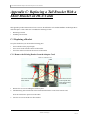
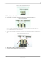
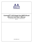
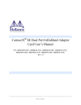
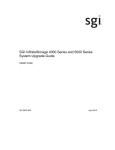
1
ConnectX® IB HCA Cards With QSFP Connectors User’s Manual P/N: MHRH19-XTC, MHRH29-XSC, MHRH29-XTC, MHQH19-XTC, MHQH29-XSC, MHQH29-XTC Rev 1.3 Mellanox Technologies 2 © Copyright 2008. Mellanox Technologies, Inc. All Rights Reserved. Mellanox Technologies, InfiniHost®, and ConnectX® are registered trademarks for Mellanox Technologies, Inc. All other marks and names mentioned herein may be trademarks of their respective companies. ConnectX® IB InfiniBand Adapter Cards With QSFP Connectors User’s Manual Document Number: 2909 Mellanox Technologies, Inc. 350 Oakmead Parkway Sunnyvale, CA 94086 U.S.A. www.mellanox.com Tel: (408) 970-3400 Fax: (408) 970-3403 Mellanox Technologies Ltd. PO Box 586 Hermon Building Yokneam 20692 Israel Tel: +972-4-909-7200 Fax: +972-4-959-3245 Rev 1.3 Mellanox Technologies ConnectX IB InfiniBand Adapter Cards With PCI Express x8 User’s Manual 3 Table of Contents Table of Contents List of Tables List of Figures Revision History About this Manual 3 4 5 6 7 Chapter 1 8 Chapter 2 Chapter 3 Overview 1.1 Adapter Cards 1.2 Mellanox Part Numbering Legend 1.3 Finding the GUID and Serial Number on the Adapter Cards 8 9 10 HCA Card Installation 11 2.1 Hardware and Software Requirements 2.2 Installation Instructions 2.3 Safety Warnings 11 11 12 Driver Software and Firmware 13 3.1 Driver Software 3.2 Updating HCA Card Firmware 3.3 Single HCA Card Firmware Update 13 13 13 Chapter 4 Adapter Card Interfaces 4.1 4.2 4.3 4.4 14 I/O Interfaces Power Memory VPD Layout for DDR/QDR Single and Dual Port HCA Cards 14 15 15 16 Appendix A Specifications 19 A.1 A.2 A.3 A.4 A.5 A.6 19 20 23 24 25 26 Board Mechanical Drawing and Dimensions EMC Certification Statements MHRH19-XTC Specifications MHQH19-XTC Specifications MHRH29-X[ST]C Specifications MHQH29-X[ST]C Specifications Appendix B Interface Connectors Pinout 27 B.1 I2C-Compatible Connector Pinout B.2 PCI Express x8 Connector Pinout B.3 QSFP Connector Pinout Appendix C Replacing a Tall Bracket With a Short Bracket on HCA Cards C.1 Replacing a Bracket 27 27 28 31 31 Appendix D Avertissements de sécurité d’installation (French) 33 Appendix E Installation - Sicherheitshinweise (German) 35 Mellanox Technologies Rev 1.3 4 List of Tables Table 1: Revision History Table 6 Table 2: Documents List 7 Table 3: HCA Cards List 8 Table 4: Mellanox HCA Cards Part Numbering Key 9 Table 5: Hardware and Software Requirements 11 Table 6: LEDs 15 Table 7: Jumper Configuration 16 Table 8: VPD Layout for MHRH[12]9-X[ST]C 16 Table 9: VPD Layout for MHQH[12]9-X[ST]C 17 Table 10: HCA Cards Certification Status 20 Table 11: Specifications for MHRH19-XTC 23 Table 12: Specifications for MHRH19-XTC 24 Table 13: Specifications for MHRH29-XSC/-XTC 25 Table 14: Specifications for MHRH29-XSC/-XTC 26 Table 15: I2C-compatible Connector Pinout 27 Table 16: Connector Pin Name and Number to Signal Name Correspondence 29 Rev 1.3 Mellanox Technologies ConnectX IB InfiniBand Adapter Cards With PCI Express x8 User’s Manual 5 List of Figures Figure 1: MH[RQ]H19-XTC Card 8 Figure 2: MH[RQ]H29-XTC Card 9 Figure 3: Card Product Label 10 Figure 4: Port Numbering 14 Figure 5: Physical and Logical Link Indications 15 Figure 6: I2C Connector 15 Figure 7: Flash Jumper 16 Figure 8: Schematic of the ConnectX IB HCA Card with QSFP Connectors 19 Figure 9: I2C-Compatible Connector Plug and Pinout 27 Figure 10: QSFP Connector Pinout 28 Figure 11: Connector and Cage Views 30 Figure 12: Adapter Card 31 Figure 13: Adapter card With Bracket Removed 32 Figure 14: Placing the Bracket 32 Figure 15: Placing the Bracket on the Card 32 Mellanox Technologies Rev 1.3 6 Revision History This document was printed on December 29, 2008 11:57 am. Table 1 - Revision History Table Date Rev December 2008 1.3 Fixed links to website Added single port cards August 2008 1.05 Added French Translation of Safety Warnings Removed Watermark April 2008 0.20 Added MHRH Changed Link from OFED to Mellanox ODFED Removed Confidential March 2008 0.10 Initial Release Rev 1.3 Comments/Changes Mellanox Technologies ConnectX IB InfiniBand Adapter Cards With PCI Express x8 User’s Manual 7 About this Manual This User’s Manual describes Mellanox Technologies MH[RQ]H[12]9-X[ST]C ConnectX IB PCI Express x8 HCA Adapter cards. It provides details as to the interfaces of the board, specifications, required software and firmware for operating the board, and relevant documentation. Intended Audience This manual is intended for the installer and user of these cards. The manual assumes basic familiarity with Infiniband® networks and architecture specifications. Related Documentation Table 2 - Documents List Mellanox Firmware Tools (MFT) User’s Manual Document no. 2204UG User’s Manual describing the set of MFT firmware management tools for a single InfiniBand node. See http://www.mellanox.com > Downloads > Firmware Tools Mellanox MST User’s Manual Document no. 2125SM This manual describes various tools and utilities, included in the Mellanox Software Tools (MST) package, for accessing, burning firmware, and tracing Mellanox silicon devices. IB Specifications Release 1.0.a Infiniband Architecture Specifications PCI Express 2.0 Specifications Industry Standard PCI Express 2.0 Card Electromechanical Specification, Rev 1.3. Online Resources • • • Mellanox Technologies Web pages: http://www.mellanox.com Mellanox Technologies Firmware download Web page: http://www.mellanox.com > Downloads > Firmware Mellanox Technologies Document Distribution System (DDS): http://docs.mellanox.com (requires a customer login account) Document Conventions When discussing memory sizes, MB and MBytes are used in this document to mean size in mega bytes. The use of Mb or Mbits (small b) indicates size in mega bits. Mellanox Technologies Rev 1.3 Overview 8 1 Overview This document is a User’s Manual for Mellanox Technologies host channel adapter (HCA) cards based on the MTץ25408 ConnectX® IB integrated circuit device. The cards described in this manual have the following main features: • • • • • • • IBTA v1.2 compliant QSFP ports for connecting InfiniBand traffic Compliant with QSFP MSA spec Rev. 1.0 Compatible with copper cable and optical cable with the use of a QSFP connector PCI Express 2.0 (1.1 compatible) through an x8 edge connector up to 5GT/s EU Restriction of Hazardous Substances (RoHS) compliant Two bracket heights: short or tall 1.1 Adapter Cards Table 3 lists the InfiniBand HCA cards described in this manual. Table 3 - HCA Cards List On-board Memory Size Short / Tall Bracket 20Gb/s (DDR) Single port No Mem Tall 40Gb/s (QDR) Single port No Mem Ordering Part Number IB Port (OPN) Speed MHRH19-XTC MHQH19-XTC Rev 1.3 HCA Card with Brackets Figure 1: MH[RQ]H19-XTC Card Tall Mellanox Technologies ConnectX IB InfiniBand Adapter Cards With PCI Express x8 User’s Manual 9 Table 3 - HCA Cards List Ordering Part Number IB Port (OPN) Speed MHRH29-XTC 20Gb/s (DDR) Dual port On-board Memory Size Short / Tall Bracket No Mem Tall Figure 2: MH[RQ]H29-XTC Card MHRH29-XSC MHQH29-XTC HCA Card with Brackets Short 40Gb/s (QDR) Dual port No Mem MHQH29-XSC Tall Short Short Bracket Tall Bracket These cards are RoHS-R5 Compliant. 1.2 Mellanox Part Numbering Legend Table 4 describes the Mellanox Technologies adapter cards part numbering legend. Table 4 - Mellanox HCA Cards Part Numbering Key HCA Card OPN MHTS#I-XBR Field Decoder M Mellanox Technologies H Adapter Type H = InfiniBand Host Channel Adapter, N = Ethernet Network Interface Card, S = Express Module T Media E=CX4 SDR, G=CX4 DDR, J=CX4 QDR, K=XFP SR, M=SFP+ SR, N=SFP+ LRM, O=SFP+ LR, Q=QSFP QDR, R=QSFP DDR, T=UTP S Silicon H = ConnectX, S = InfiniHost III Lx®, T= InfiniHost®,A = InfiniHost III Ex (Arbel), S = InfiniHost III Lx (Sinai), T = InfiniHost (Tavor) # # ports 1 = 1, 2 = 2, Mellanox Technologies Rev 1.3 Overview 10 Table 4 - Mellanox HCA Cards Part Numbering Key HCA Card OPN MHTS#I-XBR Field Decoder I Host Interface X = PCI-X, 4 = PCIe x4, 8 = PCIe x8, 9 = PCIe (SerDes @ 5.0 GT/s) G Generation <blank> = Initial product generation - Separator X Memory Size X = MemFree, 1=128MB, 2=256MB, 3=512MB B Bracket S = Short, T = Tall, N = None R RoHS <blank> = non RoHS, C = RoHS w/ Exemption, R = RoHS Lead-Free 1.3 Finding the GUID and Serial Number on the Adapter Cards All Mellanox HCA adapter cards have a label on the printed side of the adapter card that has the card serial number and the card GUID. Figure 3: Card Product Label For example, the part number MHQH29-XSC describes Mellanox Technologies’ ConnectX® IB HCA card with dual QSFP ports, a PCIe2.0 x8 5.0GT/s interface, no on-board memory (mem-free), a short PCI bracket, and RoHS R5 compliance. Using the legend, • • • • • • • • • field M = M to indicate a Mellanox Technologies product, field H = H to indicate an InfiniBand Adapter Card, field T = Q to indicate QSFP QDR, field S = H to indicate the ConnectX family, field # = 2 to indicate two ports, field I = 9 to indicate PCI Express 2.0 x8 running at 5.0GT/s, field X = X to indicate no on-board memory, field B = S to indicate a short bracket, and field R = C to indicate RoHS R5 (w/ Exemptions) compliance Rev 1.3 Mellanox Technologies ConnectX IB InfiniBand Adapter Cards With PCI Express x8 User’s Manual 11 2 HCA Card Installation 2.1 Hardware and Software Requirements Before installing the HCA Adapter card, please make sure that the system meets the hardware and software requirements listed in Table 5. Table 5 - Hardware and Software Requirements Requirement Hardware Software Operating Systems/Distributions Description PCI Express x8 or x16 slots • • For Windows see http://www.mellanox.com > Downloads > InfiniBand SW/Drivers For Linux see Mellanox OpenFabrics Enterprise Distribution (OFED) software package available via the Mellanox OpenFabrics Web site http://www.mellanox.com > Downloads > InfiniBand SW/Drivers 2.2 Installation Instructions Read all installation instructions before connecting the equipment to the power source. 2.2.1 Installation Instructions as per Host Machine The adapter cards listed in Table 3 on page 8 are standard PCI Express cards each with a standard x8 edge connector. Please consult the host machine documentation for instructions on how to install a PCI Express card. Mellanox Technologies Rev 1.3 HCA Card Installation 12 2.3 Safety Warnings 1. Installation Instructions Read all installation instructions before connecting the equipment to the power source. 2. Over-temperature This equipment should not be operated in an area with an ambient temperature exceeding the maximum recommended: 55°C (131°F). To guarantee proper air flow, allow at least 8cm (3 inches) of clearance around the ventilation openings. 3. During Lightning - Electrical Hazard During periods of lightning activity, do not work on the equipment or connect or disconnect cables. 4. Copper InfiniBand Cable Connecting/Disconnecting Copper InfiniBand cables are heavy and not flexible, as such they should be carefully attached to or detached from the connectors. Refer to the cable manufacturer for special warnings and instructions. 5. Equipment Installation This equipment should be installed, replaced, or serviced only by trained and qualified personnel. 6. Equipment Disposal Disposal of this equipment should be in accordance to all national laws and regulations. 7. Local and National Electrical Codes This equipment should be installed in compliance with local and national electrical codes. Rev 1.3 Mellanox Technologies ConnectX IB InfiniBand Adapter Cards With PCI Express x8 User’s Manual 13 3 Driver Software and Firmware 3.1 Driver Software For Linux or Windows, download and install the latest OpenFabrics Enterprise Distribution (OFED) software package available via the Mellanox OpenFabrics Web site at http://www.mellanox.com > Downloads > InfiniBand SW/ Drivers. Follow the installation instructions included in the download package. 3.2 Updating HCA Card Firmware Each HCA card is shipped with the latest version of qualified firmware at the time of manufacturing. Firmware is updated occasionally, and the most recent firmware can be obtained from http://www.mellanox.com > Downloads > Firmware. 3.3 Single HCA Card Firmware Update Firmware can be updated on the stand alone single card using the flint tool of the Mellanox Firmware Tools (MFT) package. This package is available for download, along with its user’s manual, from the Mellanox Firmware Tools page. See http://www.mellanox.com > Downloads > Firmware Tools. A firmware binaries table lists a binary file per HCA card. The file name of each such binary is composed by combining the firmware name, the firmware release version, and the card part number. Please contact Mellanox or your assigned Field Application Engineer if you cannot find the firmware binary for your adapter card. This may happen if the product is not yet available for general distribution. Mellanox Technologies Rev 1.3 Adapter Card Interfaces 14 4Adapter Card Interfaces 4.1 I/O Interfaces Each HCA card includes the following interfaces: • • • • QSFP InfiniBand Optical Connectors PCI Express x8 edge connector I/O panel LEDs I2C compatible connector (for debug) 4.1.1 InfiniBand Interface The ConnectX®IB(MT25408) device is compliant with the InfiniBand Architecture Specification, Release 1.2. It has compliant InfiniBand ports, 1 or 2, each having four Tx/Rx pairs of SerDes. Each of the HCA cards (listed in Table 3 on page 8) based on this device provides access to these ports by means of QSFP InfiniBand connectors. These cards are also compliant with the IBTA specification 1.2. Dual port cards have the following port to connector correspondence. Port 1 connects to connector 1 of the device, while port 2 connects to connector 2. Figure 4: Port Numbering Port 1 Port 2 4.1.2 PCI Express Interface The ConnectX IB HCA adapter cards support PCI Express 2.0 (1.1 compatible) through an x8 edge connector. The device can be either a master initiating the PCI Express bus operations or a slave responding to PCI bus operations. Rev 1.3 Mellanox Technologies ConnectX IB InfiniBand Adapter Cards With PCI Express x8 User’s Manual 15 4.1.3 LED Assignment The board has I/O LEDs located on the I/O panel- 2 LEDs per port. The green LED, when lit, indicates that the InfiniBand driver is running and a valid physical connection between nodes exists. If the green LED is blinking, it indicates a problem with the physical link. The yellow LED when lit, indicates a valid data activity link, this is the logical link. The yellow LED illuminates when the InfiniBand network is discovered over the physical link. A valid data activity link without data transfer is designated by a constant yellow LED indication. A valid data activity link with data transfer is designated by a blinking yellow LED indication. If the LEDs are not active, either the physical link or the logical link (or both) connections have not been established. Figure 5: Physical and Logical Link Indications Table 6 - LEDs Port Number LED Name Port 1 Physical Link - Green Constant on indicates a good physical link Blinking indicates a problem with the Physical link Port 1 Data Activity - Yellow Blinking indicates Data Transfer Constant on indicates no Data Transfer Port 2 Physical Link - Green Constant on indicates a good physical link Blinking indicates a problem with the Physical link Port 2 Data Activity - Yellow Blinking indicates Data Transfer Constant on indicates no Data Transfer Note: The short bracket has the same port and LED footprint as the tall bracket. 4.1.4 I2C Compatible Interface A three-pin header on the HCA card is provided as the I2C compatible interface. See Figure 8 on page 19 for the location on the board. Figure 6: I2C Connector 4.2 Power All adapter cards receive 12V and 3.3V power from the PCI Express Edge connector. All other required power voltages are generated by on-board switch mode regulators. See “Specifications” on page 19. 4.3 Memory The HCA cards support multiple memory devices through the PCI Flash, and I2C-compatible interfaces. Mellanox Technologies Rev 1.3 Adapter Card Interfaces 16 4.3.1 System Memory Each of the HCA cards utilizes the PCI Express interface to store and access IB fabric connection information and packet data on the system memory. 4.3.2 Flash Each of the HCA cards includes one 2MB SPI Flash device (M25P80 device by ST Microelectronics) accessible via the Flash interface of the MT25408 ConnectX IB device. There is a jumper on each adapter card that indicates to the device whether an on-board Flash device is to be used. Table 7 provides information on this jumper. See Figure 8 on page 19 for the jumper location. Table 7 - Jumper Configuration Description Card Default Configuration Option Flash present/ not present connection open – Flash present connection shorted – Flash not present connection open – Flash present Comments Header 1x2 Figure 7: Flash Jumper 4.3.3 EEPROM Each board incorporates an EEPROM that is accessible through the I2C-compatible interface. The EEPROM is used for storing the Vital Product Data (VPD). The VPD format adheres to the PCI Local Bus specification rev 2.3 VPD definition. The EEPROM capacity is 512 bytes. 4.4 VPD Layout for DDR/QDR Single and Dual Port HCA Cards The PCI VPD (Vital Product Data) layout, for each of the described Mellanox Technologies ConnectX IB HCA adapter cards, complies with the format defined in the PCI 2.3 Specification, Appendix I. All ConnectX IB HCA adapter cards share the same PCI VPD layout.“A1” was used as the HCA card (PCB) revision. Later revisions of the HCA card will have the same format. Table 8 - VPD Layout for MHRH[12]9-X[ST]C Offset (Decimal) Item Value 0 Large Resource Type ID String Tag (0x02) 0x82 1 Length [7:0] LSB 0xD 2 Length [15:8] MSB 0x0 3 Data FALCON IB QDR 16 Large Resource Type VPD-R Tag (0x10) 0x90 17 Length [7:0] LSB 0x4F 18 Length [15:8] MSB 0x00 Rev 1.3 Mellanox Technologies Format STR Description ConnectX IB InfiniBand Adapter Cards With PCI Express x8 User’s Manual 17 Table 8 - VPD Layout for MHRH[12]9-X[ST]C Offset (Decimal) Item Value Format Description 19 21 VPD Keyword PN STR Add in Card Part Number Length 0x15 22 PN PN %STR_SPC 43 VPD Keyword EC STR 45 Length 0x2 Engineering Change Level of the card (rev) 46 Revision A1 %STR PCB revision 48 VPD Keyword SN STR Serial Number 50 Length 0x18 51 SerialNumber %STR_SPC “00..00XXXX..XX” 75 VPD Keyword V0 STR Misc Information 77 Length 0x10 78 Data PCIe Gen2 x8 STR_SPC 94 VPD Keyword RV STR 96 Length 0x1 97 Data 0,96 98 Large Resource Type VPD-W Tag (0x11) 0x91 %CS0 99 Length [7:0] LSB 0x9A 100 Length [15:8] MSB 0x00 101 VPD Keyword V1 103 Length 0x6 104 Data N/A STR_SPC 110 VPD Keyword YA STR Asset Tag 112 Length 0x20 113 Data N/A STR_SPC “N/A” 145 VPD Keyword RW STR Remaining read/write area 147 Length 0x6b STR_ZERO Reserved (0x00) 148 Data 255 Small Resource Type END Tag (0x11) STR EFI Driver version 0x78 Table 9 - VPD Layout for MHQH[12]9-X[ST]C Offset (Decimal) Item Value 0 Large Resource Type ID String Tag (0x02) 0x82 1 Length [7:0] LSB 0xD 2 Length [15:8] MSB 0x0 3 Data FALCON IB QDR 16 Large Resource Type VPD-R Tag (0x10) 0x90 17 Length [7:0] LSB 0x4F 18 Length [15:8] MSB 0x00 Mellanox Technologies Format Description STR Rev 1.3 Adapter Card Interfaces 18 Table 9 - VPD Layout for MHQH[12]9-X[ST]C Offset (Decimal) Item 19 21 Rev 1.3 Value Format Description VPD Keyword PN STR Add in Card Part Number Length 0x15 22 PN PN %STR_SPC 43 VPD Keyword EC STR 45 Length 0x2 Engineering Change Level of the card (rev) 46 Revision A1 %STR PCB revision 48 VPD Keyword SN STR Serial Number 50 Length 0x18 51 SerialNumber %STR_SPC “00..00XXXX..XX” 75 VPD Keyword V0 STR Misc. Information 77 Length 0x10 78 Data PCIe Gen2 x8 STR_SPC 94 VPD Keyword RV STR 96 Length 0x1 97 Data 0,96 98 Large Resource Type VPD-W Tag (0x11) 0x91 %CS0 99 Length [7:0] LSB 0x9A 100 Length [15:8] MSB 0x00 101 VPD Keyword V1 103 Length 0x6 104 Data N/A STR_SPC 110 VPD Keyword YA STR Asset Tag 112 Length 0x20 113 Data N/A STR_SPC “N/A” 145 VPD Keyword RW STR Remaining read/write area 147 Length 0x6b STR_ZERO Reserved (0x00) 148 Data 255 Small Resource Type END Tag (0x11) 0x78 Mellanox Technologies STR EFI Driver version ConnectX IB InfiniBand Adapter Cards With PCI Express x8 User’s Manual 19 Appendix A: Specifications A.1 Board Mechanical Drawing and Dimensions All of the HCA cards covered in this User’s Manual have the same mechanical drawing and share the same dimensions as depicted in Figure 8. Note: All dimensions are in millimeters. Figure 8: Schematic of the ConnectX IB HCA Card with QSFP Connectors 167.65 68.90 56.97 15.00 3.65 J1 – I2C Connector 1.90 J4 – Flash Jumper 33.35 43.17 57.15 96.30 Mellanox Technologies Rev 1.3 20 A.2 EMC Certification Statements Table 10 lists the approved certification status per HCA card in different regions of the world. Table 10 - HCA Cards Certification Status Rev 1.3 VCCI (Japan) MIC/BCC (Korea) Class A Class A Class A Class A Class A Class A Class A Class A Class A Class A Class A Class A MHRH29-XTC Class A Class A Class A Class A Class A MHQH29-XSC Class A Class A Class A Class A Class A MHQH29-XTC Class A Class A Class A Class A Class A HCA Card P/N FCC Class (USA) EN Class (Europe) ICES Class (Canada) MHRH19-XTC Class A Class A MHQH19-XTC Class A MHRH29-XSC Mellanox Technologies ConnectX IB InfiniBand Adapter Cards With PCI Express x8 User’s Manual 21 FCC Statements (USA) Class A Statements: § 15.21 Statement Warning! Changes or modifications to this equipment not expressly approved by the party responsible for compliance (Mellanox Technologies) could void the user's authority to operate the equipment. §15.105(a) Statement NOTE: This equipment has been tested and found to comply with the limits for a Class A digital device, pursuant to Part 15 of the FCC Rules. These limits are designed to provide reasonable protection against harmful interference when the equipment is operated in a commercial environment. This equipment generates, uses, and can radiate radio frequency energy and, if not installed and used in accordance with the instruction manual, may cause harmful interference to radio communications. Operation of this equipment in a residential area is likely to cause harmful interference in which case the user will be required to correct the interference at his own expense. A.2.1 EN Statements (Europe) EN55022 Class A Statement: Warning This is a class A product. In a domestic environment this product may cause radio interference in which case the user may be required to take adequate measures. A.2.2 ICES Statements (Canada) Class A Statement: “This Class A digital apparatus complies with Canadian ICES-003. Cet appareil numérique de la classe A est conforme à la norme NMB-003 du Canada.” Mellanox Technologies Rev 1.3 22 A.2.3 VCCI Statements (Japan) Class A Statement: (Translation - "This is a Class A product based on the standard of the Voluntary Control Council for Interference by Information Technology Equipment (VCCI). If this equipment is used in a domestic environment, radio interference may occur, in which case the user may be required to take corrective actions.") Rev 1.3 Mellanox Technologies ConnectX IB InfiniBand Adapter Cards With PCI Express x8 User’s Manual 23 A.3 MHRH19-XTC Specifications Table 11 - Specifications for MHRH19-XTC Physical Power and Environmental Size: Air Flow: QSFP 20Gb/s Connector: 2.71in. x6.60in. (68.90mm x 167.65mm) 200LFM @55°C IBTA v1.2, Auto-Negotiation1 (20Gb/s, 5Gb/s) or (10Gb/s, 2.5Gb/s) QoS: 8 InfiniBand Virtual Lanes for each port PCI Express 12V, 3.3V 12W max. for passive cables only 14.5W max. for active optic modules 0°C to 55°C Regulatory InfiniBand: Data Rate: Temperature: InfiniBand (Copper and optical) Max power per port 3.5 W. Protocol Support RDMA Support: Voltage: Maximum Power: EMC: Yes, All Ports DDR 2.0 SERDES @ 5.0 GT/s Safety: Environmental: RoHS: FCC 47 CFR part 15:2006, subpart B, class A ICES-003:2004 Issue 4, class A VCCI V-3/2007.04, class A EN 55022:1998+A1:2000+A2:2003 class A, EN 61000-3-2:2000+A2:2005, EN61000-3-3:1995+A2:2005, EN 55024:1998 + A1:2001+A2:2003 standards, harmonized under EMC Directive 2004/108/EC Article 6(2); AS/NZS 3548 IEC/EN 60950-1:2001 ETSI EN 300 019-2-2 IEC 60068-2- 64, 29, 32 RoHS-R5 1. The auto-negotiation protocol is proprietary of Mellanox Technologies and compliant with the InfiniBand Architecture Specification, Release 1.2. Mellanox Technologies Rev 1.3 24 A.4 MHQH19-XTC Specifications Table 12 - Specifications for MHRH19-XTC Physical Power and Environmental Size: Air Flow: QSFP 40Gb/s Connector: 2.71in. x6.60in. (68.90mm x 167.65mm) 200LFM @55°C IBTA v1.2, Auto-Negotiation1 (20Gb/s, 5Gb/s) or (10Gb/s, 2.5Gb/s) QoS: 8 InfiniBand Virtual Lanes for each port PCI Express 12V, 3.3V 12.6W max. for passive cables only 15.1W max. for active optic modules 0°C to 55°C Regulatory InfiniBand: Data Rate: Temperature: InfiniBand (Copper and optical) Max power per port 3.5 W. Protocol Support RDMA Support: Voltage: Maximum Power: EMC: Yes, All Ports QDR 2.0 SERDES @5.0 GT/s Safety: Environmental: RoHS: FCC 47 CFR part 15:2006, subpart B, class A ICES-003:2004 Issue 4, class A VCCI V-3/2007.04, class A EN 55022:1998+A1:2000+A2:2003 class A, EN 61000-3-2:2000+A2:2005, EN61000-3-3:1995+A2:2005, EN 55024:1998 + A1:2001+A2:2003 standards, harmonized under EMC Directive 2004/108/EC Article 6(2); AS/NZS 3548 IEC/EN 60950-1:2001 ETSI EN 300 019-2-2 IEC 60068-2- 64, 29, 32 RoHS-R5 1. The auto-negotiation protocol is proprietary of Mellanox Technologies and compliant with the InfiniBand Architecture Specification, Release 1.2. Rev 1.3 Mellanox Technologies ConnectX IB InfiniBand Adapter Cards With PCI Express x8 User’s Manual 25 A.5 MHRH29-X[ST]C Specifications Table 13 - Specifications for MHRH29-XSC/-XTC Physical Power and Environmental Size: Air Flow: QSFP 20Gb/s Connector: 2.71in. x6.60in. (68.90mm x 167.65mm) 200LFM @55°C IBTA v1.2, Auto-Negotiation1 (20Gb/s, 5Gb/s) or (10Gb/s, 2.5Gb/s) QoS: 8 InfiniBand Virtual Lanes for each port PCI Express 12V, 3.3V 13W max. for passive cables only 18W max. for active optic modules 0°C to 55°C Regulatory InfiniBand: Data Rate: Temperature: InfiniBand (Copper and optical) Max power per port 3.5 W. Protocol Support RDMA Support: Voltage: Maximum Power: EMC: Yes, All Ports DDR 2.0 SERDES @ 5.0 GT/s Safety: Environmental: RoHS: FCC 47 CFR part 15:2006, subpart B, class A ICES-003:2004 Issue 4, class A VCCI V-3/2007.04, class A EN 55022:1998+A1:2000+A2:2003 class A, EN 61000-3-2:2000+A2:2005, EN61000-3-3:1995+A2:2005, EN 55024:1998 + A1:2001+A2:2003 standards, harmonized under EMC Directive 2004/108/EC Article 6(2); AS/NZS 3548 IEC/EN 60950-1:2001 ETSI EN 300 019-2-2 IEC 60068-2- 64, 29, 32 RoHS-R5 1. The auto-negotiation protocol is proprietary of Mellanox Technologies and compliant with the InfiniBand Architecture Specification, Release 1.2. Mellanox Technologies Rev 1.3 26 A.6 MHQH29-X[ST]C Specifications Table 14 - Specifications for MHRH29-XSC/-XTC Physical Power and Environmental Size: Air Flow: QSFP 40Gb/s Connector: 2.71in. x6.60in. (68.90mm x 167.65mm) 200LFM @55°C IBTA v1.2, Auto-Negotiation1 (20Gb/s, 5Gb/s) or (10Gb/s, 2.5Gb/s) QoS: 8 InfiniBand Virtual Lanes for each port PCI Express 12V, 3.3V 13.5W max. for passive cables only 18.5W max. for active optic modules 0°C to 55°C Regulatory InfiniBand: Data Rate: Temperature: InfiniBand (Copper and optical) Max power per port 3.5 W. Protocol Support RDMA Support: Voltage: Maximum Power: EMC: Yes, All Ports QDR 2.0 SERDES @ 5.0GT/s Safety: Environmental: RoHS: FCC 47 CFR part 15:2006, subpart B, class A ICES-003:2004 Issue 4, class A VCCI V-3/2007.04, class A EN 55022:1998+A1:2000+A2:2003 class A, EN 61000-3-2:2000+A2:2005, EN61000-3-3:1995+A2:2005, EN 55024:1998 + A1:2001+A2:2003 standards, harmonized under EMC Directive 2004/108/EC Article 6(2); AS/NZS 3548 IEC/EN 60950-1:2001 ETSI EN 300 019-2-2 IEC 60068-2- 64, 29, 32 RoHS-R5 1. The auto-negotiation protocol is proprietary of Mellanox Technologies and compliant with the InfiniBand Architecture Specification, Release 1.2. Rev 1.3 Mellanox Technologies ConnectX IB InfiniBand Adapter Cards With PCI Express x8 User’s Manual 27 Appendix B: Interface Connectors Pinout B.1 I2C-Compatible Connector Pinout Figure 7: I2C-Compatible Connector Plug and Pinout Table 15 - I2C-compatible Connector Pinout 4 3 2 1 5 5 1 2 3 4 Connector Pin Number HCA Signal Name 1 SPSDA 2 SPSCL 3 GND 4 NC 5 NC B.2 PCI Express x8 Connector Pinout These cards use a standard PCI Express x8 edge connector and the PCI Express x8 standard pinout according to the PCI Express 2.0 specification. Mellanox Technologies Rev 1.3 28 B.3 QSFP Connector Pinout Figure 8: QSFP Connector Pinout 20 21 22 23 24 25 26 27 28 29 30 GND Rx2n Rx1n 18 Rx2p Rx1p 17 GND GND 16 Rx4n Rx3n Rx4p Rx3p GND GND ModPrsL SDA IntL SCL VccTx Vcc Rx Vcc1 ResetL 15 14 13 12 11 10 9 8 31 LPMode 32 GND GND 33 Tx3p Tx4p 34 Tx3n 35 GND Tx4n GND 36 Tx1p Tx2p 3 Tx1n GND Tx2n 2 1 37 38 Rev 1.3 19 GND ModSelL GND Mellanox Technologies 7 6 5 4 ConnectX IB InfiniBand Adapter Cards With PCI Express x8 User’s Manual 29 Table 16 - Connector Pin Name and Number to Signal Name Correspondence Connector Pin Number Connector Pin Name IB Port A Signal Name 1 GND GND 2 TXN_2 Tx2n 3 TXP_2 Tx2p 4 GND GND 5 TXN_4 Tx4n 6 TXP_4 Tx4p 7 GND GND 8 ModSelL_Port0 ModSelL 9 ResetL_Port0 ResetL 10 VccRx 11 SCL SCL 12 SDA SDA 13 GND GND 14 RXP_3 Rx3p 15 RXN_3 Rx3n 16 GND GND 17 RXP_1 Rx1p 18 RXN_1 Rx1n 19 GND GND 20 GND GND 21 RXN_2 Rx2n 22 RXP_2 Rx2p 23 GND GND 24 RXN_4 Rx4n 25 RXP_4 Rx4p 26 GND GND 27 ModPrsl_Port0 Mod PrsL 28 IntL IntL 29 VccTx 30 Vcc1 31 LPMode_Port0 LPMode 32 GND GND 33 TXP_3 Tx3p 34 TXN_3 Tx3n 35 GND GND 36 TXP_1 Tx1p 37 TXN_1 Tx1n 38 GND GND Mellanox Technologies Rev 1.3 16 17 18 19 SCL SDA GND RX3p RX3n GND RX1p RX1n GND 8 ResetL VccRx 15 7 ModSelL 20 GND 21 RX2n 22 RX2p 23 GND 24 RX4n 25 RX4p 26 GND 27 ModPrsL 28 IntL 29 VccTx 30 Vcc1 31 LPMode 32 GND 14 13 12 11 1 0 9 8 7 6 5 4 3 2 1 GND 14 6 GND 15 TX2n 33 TX3p TX2p 13 5 TX4p 16 GND 34 TX3n TX4n 12 4 TX4n TX4p 19 18 17 GND 35 GND ModSelL 11 1 0 9 3 GND ResetL 36 TX1p SCL 2 TX2p SDA 1 TX2n GND 37 TX1n RX3p 38 GND GND 3 8 TX1n 3 7 TX1p 3 6 GND 3 5 TX3n 3 4 TX3p 3 3 GND 3 2 RX3n VccRx GND RX1p RX1n Top 18.35 LPMode 3 1 Vcc1 30 VccTx 29 IntL 28 ModPrsL 27 GND 26 RX4p 25 RX4n 24 GND 23 RX2p 22 RX2n 21 GND 20 GND Mellanox Technologies Rev 1.3 GND 30 Figure 9: Connector and Cage Views Top 18.35 View into Rear of Connector 8.50 View into Front of Cage 8.50 ConnectX IB InfiniBand Adapter Cards With PCI Express x8 User’s Manual 31 Appendix C: Replacing a Tall Bracket With a Short Bracket on HCA Cards This appendix provides instructions on how to remove the tall bracket of a standard Mellanox Technologies HCA card and replace it with a short one. It includes the following sections: • • Removing a bracket Installing a new bracket C.1 Replacing a Bracket To replace the bracket you will need the following parts: • • • the new bracket of the proper height the 2 screws saved from the removal of the bracket the 2 fiber washers saved from the removal of the bracket C.1.1 Remove the Existing Bracket from the Adapter Card Figure 10: Adapter Card LEDs Once the screws are removed push here with equal pressure on each side. two screws with black fiber washers 1 2. Remove the two screws holding the bracket in place. Simultaneously push on both ends of the bracket until the bracket comes loose from the card. Note: Be careful not to put stress on the LEDs. 3. Save the two screws and the two fiber washers. Mellanox Technologies Rev 1.3 32 Figure 11: Adapter card With Bracket Removed C.1.2 Installing the New Bracket 4. Place the bracket over the connector cages and push the bracket onto the card until the screw holes line up. Figure 12: Placing the Bracket Note: Do not force the bracket onto the card. You may have to gently push the LEDs using a small screwdriver to align the LEDs with the holes in the bracket. 5. Take the screws and washers saved from Step 1. Place the screws and washers into the holes and screw them in snug. Figure 13: Placing the Bracket on the Card 6. Make sure that the LEDs are aligned onto the bracket holes. 7. Use a torque driver to apply up to 2 lbs-in torque on the screws. Rev 1.3 Mellanox Technologies ConnectX IB InfiniBand Adapter Cards With PCI Express x8 User’s Manual 33 Appendix D: Avertissements de sécurité d’installation (French) 1. Instructions d’installation Lisez toutes les instructions d’installation avant de brancher le matériel à la source d’alimentation électrique. 2. Température excessive Ce matériel ne doit pas fonctionner dans une zone avec une température ambiante dépassant le maximum recommandé de 55°C (131°F). Un flux d’air de 200LFM à cette température ambiante maximale est nécessaire. En outre, pour garantir un bon écoulement de l’air, laissez au moins 8 cm (3 pouces) d’espace libre autour des ouvertures de ventilation. 3. Orages – dangers électriques Pendant un orage, il ne faut pas utiliser le matériel et il ne faut pas brancher ou débrancher les câbles. 4. Branchement/débranchement des câbles InfiniBand en cuivre Les câbles InfiniBand en cuivre sont lourds et ne sont pas flexibles, il faut donc faire très attention en les branchant et en les débranchant des connecteurs. Consultez le fabricant des câbles pour connaître les mises en garde et les instructions spéciales. 5. Installation du matériel Ce matériel ne doit être installé, remplacé ou entretenu que par du personnel formé et qualifié. 6. Elimination du matériel L’élimination de ce matériel doit s’effectuer dans le respect de toutes les législations et réglementations nationales en vigueur. Mellanox Technologies Rev 1.3 34 7. Codes électriques locaux et nationaux Ce matériel doit être installé dans le respect des codes électriques locaux et nationaux. Rev 1.3 Mellanox Technologies ConnectX IB InfiniBand Adapter Cards With PCI Express x8 User’s Manual 35 Appendix E: Installation - Sicherheitshinweise (German) 1. Installationsanleitungen Lesen Sie alle Installationsanleitungen, bevor Sie das Gerät an die Stromversorgung anschließen. 2. Übertemperatur Dieses Gerät sollte nicht in einem Bereich mit einer Umgebungstemperatur über der maximal empfohlenen Temperatur von °C (°F) betrieben werden. Es ist ein Luftstrom von 200 LFM bei maximaler Umgebungstemperatur erforderlich. Außerdem sollten mindestens 8 cm (3 in.) Freiraum um die Belüftungsöffnungen sein, um einen einwandfreien Luftstrom zu gewährleisten. 3. Bei Gewitter - Elektrische Gefahr Arbeiten Sie während eines Gewitters und Blitzschlag nicht am Gerät, schließen Sie keine Kabel an oder ab. 4. Anschließen/Trennen von InfiniBand-Kupferkabel InfiniBand-Kupferkabel sind schwer und nicht flexible. Deshalb müssen sie vorsichtig an die Anschlüsse angebracht bzw. davon getrennt werden. Lesen Sie die speziellen Warnungen und Anleitungen des Kabelherstellers. 5. Geräteinstallation Diese Gerät sollte nur von geschultem und qualifiziertem Personal installiert, ausgetauscht oder gewartet werden. 6. Geräteentsorgung Die Entsorgung dieses Geräts sollte unter Beachtung aller nationalen Gesetze Bestimmungen erfolgen. Mellanox Technologies Rev 1.3 36 7. Regionale und nationale elektrische Bestimmungen Dieses Gerät sollte unter Beachtung der regionalen und nationalen elektrischen Bestimmungen installiert werden. Rev 1.3 Mellanox Technologies