1
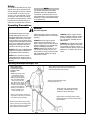
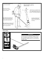
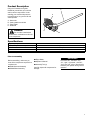
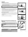
SHINDAIWA OWNER’S/OPERATOR’S MANUAL
MULTIPURPOSE
EDGER TOOL 65010
Minimize the risk of injury to yourself and others!
Read this manual and familiarize yourself with the
contents. Always wear eye and hearing protection
WARNING! when operating this unit.
X7502880402
12/10
Introduction
The Multipurpose Edger Tool has been
designed and built to deliver superior performance and reliability without
compromise to quality, comfort, safety
or durability.
While every attempt has been made
to provide the latest information about
your Shindaiwa product, there may be
some differences between your attachment and what is described here.
As an owner/operator, you’ll soon discover for yourself why Shindaiwa is
simply in a class by itself!
ECHO, Inc. reserves the right to
make changes to products without
prior notice, and without obligation to
make alterations to units previously
manufactured.
Contents
PAGE
Attention Statements........................... 2
Safety.................................................. 3
Product Description............................. 5
IMPORTANT!
The information contained in these
instructions describes units available at
the time of publication.
PAGE
Specifications...................................... 5
Assembly............................................. 6
Using a Hand-Held Edger................... 8
PAGE
Maintenance........................................ 8
Troubleshooting Guide...................... 11
IMPORTANT!
The operational procedures described in this manual are intended to help you get the most from this unit as well as to protect you and others from harm. These procedures are guidelines for safe operation under most conditions, and are not
intended to replace any safety rules and/or laws that may be in force in your area. If you have questions regarding your
Shindaiwa hand held power equipment, or if you do not understand something in this manual, contact your local Shindaiwa
dealer for assistance. You may also contact Shindaiwa at the address printed on the back of this Manual.
Attention Statements
Throughout this manual are special
“attention statements”.
DANGER!
A statement preceded by
the triangular attention symbol and
the word “DANGER” contains information that should be acted upon
to prevent serious injury or death.
WARNING!
A statement preceded by
the triangular attention symbol and
the word “WARNING” contains information that should be acted upon to
prevent serious bodily injury.
A statement preceded by the word
“CAUTION” contains information
that should be acted upon to prevent mechanical damage.
IMPORTANT!
A statement preceded by the word
“NOTE” contains information that is
handy to know and may make your job
easier.
A statement preceded by the word
“IMPORTANT” is one that possesses
special significance.
International Symbols
Keep bystanders
at least 50 feet (15 m)
away during operation.
Beware of thrown or
ricocheted objects.
2
CAUTION!
Keep feet away from
blade. Rotating blade
may cause injury.
Blade may continue to
rotate after the unit is
shut off.
NOTE:
Safety
This machine operates at very high
speeds and has the potential to do
serious damage if misused, abused
or mishandled. To reduce the risk
of injury, you must maintain control
at all times, and observe all safety
precautions during operation. Never
permit a person without training or
instruction to operate this machine!
NOTE:
For specific maintenance and safety
information about your Multipurpose
Tool Carrier, consult the owner's manual provided with it. If it has been lost or
misplaced, contact a Shindaiwa dealer
for a replacement.
Operating Precautions
WARNING!
Use Good Judgement
This Shindaiwa edger tool is specifically designed for use on the
Shindaiwa Multipurpose Tool Carrier.
Installation and/or use on any other
model, brand or type of power tool is
not approved by Shindaiwa. Attempts
to use on non-approved models can
damage the equipment and cause
accidents, serious injury or death.
ALWAYS make sure the Multipurpose
Edger Tool is properly installed and
firmly tightened before operation.
NEVER use a cracked or warped
cutting attachment: replace it with a
serviceable one and make sure it fits
properly
Before starting the engine, make sure
the cutting attachment is not contacting
anything.
ALWAYS stop the engine immediately and check for damage if you
strike a foreign object or if the machine
becomes tangled. Do not operate with
broken or damaged equipment.
NEVER transport the machine or set
it down with the engine running. An
engine that’s running could be accidentally accelerated causing the cutting
attachment to rotate.
ALWAYS stop the engine immediately if it suddenly begins to vibrate
or shake. Inspect for broken, missing or improperly installed parts or
attachments.
ALWAYS keep a Solid Stance. Maintain footing and balance at all times.
Do not stand on slippery, uneven or
unstable surfaces. Do not work in odd
positions or on ladders. Do not over
reach.
Operating the Multipurose Edger Tool
Always wear a hard
hat to reduce the risk
of head injuries during
operation of this
machine.
ALWAYS protect yourself
from hazards such as
thorny brush and flying
debris by wearing gloves
and close fitting clothing
that covers arms and
legs. Never wear shorts.
Don't wear loose clothing
or items such as jewelry
that could get caught in
machinery or underbrush.
Secure long hair so it is
above shoulder level.
Keep a proper footing and do not
overreach—maintain your balance
at all times during operation.
Always wear eye protection such as goggles or
safety glasses. Wear hearing protection devices
and a broad-brimmed hat or helmet.
Always operate with both hands
firmly gripping the unit.
Keep away from rotating attachments
at all times, and NEVER lift a moving
attachment above waist-height.
Always make sure the appropriate cutting
attachment shield is correctly installed and in
good condition.
Wear sturdy footwear with nonslip
soles to provide good footing. Steeltoed safety boots are recommended.
Never operate unit bare-footed!
3
Avoid long-term operation in very
hot or very cold weather.
Make sure bystanders or observers
outside the 15 meters “danger zone”
wear eye protection.
Be extremely careful of
slippery terrain, especially
during rainy weather.
Reduce the risk of bystanders being
struck by flying debris. Make sure no
one is within 15 meters—that’s about
16 paces—of an operating attachment.
Be constantly alert for objects and
debris that could be thrown either
from the rotating cutting attachment
or bounced from a hard surface.
If contact is made with a hard
object, stop the engine and
inspect the cutting attachment
for damage.
When operating in rocky terrain or near
electric wires or fences, use extreme
caution to avoid contacting such items
with the cutting attachment.
Safety Labels
SHINDAIWA OWNER’S/
OPERATOR’S MANUAL
50 FEET
(15m)
IMPORTANT!
MULTIPURPOSE
Safety and Information Labels: Make sure all safety and
EDGER TOOL information labels are undamaged, readable and up to
KEEP BYSTANDERS AWAY
AT LEAST 50 FEET (15m)
date. Immediately replace damaged or missing labels.
New labels are available through your local authorized
Shindaiwa dealer.
WARNING!
Always
wear eye and
BEWARE OF THROWN OR
OBJECTS
earRICHOCHETED
protection
when
operating this machine!
1439
WARNING!
KEEP AWAY FROM
ROTATING BLADE
To minimize the risk of
injury to yourself and
others, read this manual
and familiarize yourself
with its contents.
Shindaiwa Inc.
1440
4
Product Description
Using the illustration as a guide,
familiarize yourself with your machine
and its various components. Understanding your machine helps ensure
top performance, long service life and
safer operation.
A
B
A - Outer tube
B - Cutting attachment shield
C - Edger blade
D - Gearcase
WARNING!
Do not make unauthorized
modifications or alterations to this unit
or its components.
C
D
Specifications
Length/Weight/Height
Multipurpose Edger Tool (less cutting attachment)
Gearcase Lubrication
Gear Reduction
Gearcase Arbor Bolt Size
793 x 171 x 299 mm (31.2 x 6.7 x 11.8 in)
1.98 kg (4.4 lb)
Lithium based grease
1.36:1
8 mm Left-hand thread
Specifications are subject to change without notice.
Prior to assembly
Before assembling, make sure you
have all the components required for a
complete unit:
■■Shaft/Gearcase Assembly
■■Shield/Wheel Assembly
IMPORTANT!
■■Edger Blade
■■Operator’s Manual
■■Assembly Tool (s)
Carefully inspect all components for
damage.
65010-94010_MLE230_07LP
9
The terms “left”, “left-hand”, and
“LH”; “right”, “right-hand”, and “RH”;
“front” and “rear” refer to directions as
viewed by the operator during normal
operation.
11/21/01, 11:19 AM
5
Assembly
Installing a Tool Attachment
A
1. Place the Multipurpose Tool Carrier (A) and the Tool Assembly (B) on a clean,
flat surface so that both assemblies fit end to end. The powerhead assembly
should be facing up, and the tool assembly should be positioned with the locking hole in the tube (C) end facing up.
G
F
C
CAUTION!
Keep the open ends of the tubes clean and free of Debris!
2. Slip off the protective cover from the end of the tool, and loosen the coupler
screw knob (D).
3. Insert the tool assembly into the coupler (E), with the tool decal facing up, until
the line of the decal is flush with the end of the coupler. Twist the tool back and
forth until you are sure it snaps in place by the coupler latch (F).
4. When the two tube halves are locked together, press down on the springloaded latch protector (G) and tighten the coupler screw knob.
M23004
D
B
E
E
G
Disassembling The Pole Sections
1. Place the Multipurpose Tool Carrier and the Tool Assembly on a clean, flat surface, loosen the coupler screw knob (D). The spring-loaded coupler protector
(G) should pop up.
2. Press down on the latch (F) with your finger or thumb. This releases the coupler latch.
3. Pull the tool assembly (B) out of the coupler (E).
M23005
D
M23006
Mount the Cutting Attachment Shield on the
Gearcase
1. Remove the shaft bolt, bolt guard, holder A and holder B from the gearcase.
2. Align the cutting attachment shield assembly (A) with the gearcase as shown,
and then fit the shield onto the matching flange (B) on the gearcase.
A
26019
B
WARNING!
The edger is intended for right-handed operation only! When correctly assembled, the cutting attachment shield and shaft must be oriented as
shown.
E
3. Install the socket-head screws (C) with washers. Firmly tighten all three
screws.
4. Install a washer (D) and nut (E) on each of the three screws assembled in
Step 3, then firmly tighten each nut.
ASSEMBLY
26020
IMPORTANT!
The three socket-head screws must be firmly tightened against the cutting attachment shield before installing and tightening the nuts.
6
D
C
Mount the Cutting Attachment
Shield on the Gearcase
1. Remove the shaft bolt, bolt guard,
holder A and holder B from the
gearcase. See Figure 5.
2. Align the cutting attachment shield
assembly with the gearcase as
shown, and then fit the shield onto
the matching flange on the
gearcase. See Figure 5.
WARNING!
Mount the
1. Install the
shaft. See
2. Mount th
B onto th
install th
(turn bol
install). S
3. Align the
matched
then use
temporar
See Figu
Mount the Edger Blade
1. Install the holder (A) onto the output shaft (D).
2. Mount the edger blade (C) and holder (B) onto the output shaft, and then
install the bolt guard (E) and shaft bolt (F) (turn bolt counterclockwise to
install).
3. Align the hole in holder (A) with the matched hole in the gearcase, and then
use the hex wrench to temporarily lock the output shaft.
4. Firmly tighten the shaft bolt. Remove the hex wrench.
D
E
F
26018
A
B
WARNING!
C
■■The edger is designed for use with an edger blade only!
■■Never operate the edger without the cutting attachment shield installed and
tightly secured!
The Multipurpose Edger Tool should now be completely
assembled.
Adjusting blade cutting depth
The edger’s depth of cut is controlled
by a combination of operator height,
blade wear, and the positioning of the
edger’s guide wheel.
B
To adjust blade height:
1. Loosen the guide wheel adjusting
knob (A).
2. Raise or lower the guide wheel (B)
to the desired setting.
3. Tighten the guide wheel adjusting
knob firmly.
WARNING!
A
Use only Shindaiwa
replacement edger blades.
WARNING!
Never adjust the guide
wheel while the engine is running.
NOTE:
Guide wheel adjustment is also
required to compensate for blade wear.
NOTE:
C
65010-94010_MLE230_07LP
10
11/21/01, 11:19 AM
The numbers (C) are for reference
only; they do NOT refer to depth in
inches
7
Using a Hand-Held Edger
Guidelines for Operating the
Edger
■■Before edging, make sure the area
WARNING!
is soft enough so the blade does not
bog down. If necessary, water the
area before edging.
■■Remove debris and other obstacles
that could be thrown by the rotating
blade.
■■Plan your work so the edger blade
is always on your right-hand side.
■■Wear eye protection, long pants,
and boots when operating this
machine!
■■Whenever you strike a hardo
bject with the blade, always stop
the edger and carefully inspect
the blade for damage. NEVER
OPERATE THE EDGER WITH A
DAMAGED BLADE!
■■Begin each pass by positioning the
unit over the work, and with the
engine running at about half-throttle.
Slowly lower the blade to the ground
while applying full throttle.
CAUTION!
Low-speed edging can lead to premature clutch failure.
■■Do not move the edger into the work
so fast that the engine or blade bogs
down.
Regular and frequent use of the edger
will make a neater lawn, and a frequently trimmed edge will be easier to
maintain.
Figure 10
Maintenance
IMPORTANT!
For detailed maintenance information
about your Multipurpose Tool Carrier,
consult the owner’s manual that was
provided with it. If it has been lost or
misplaced, contact Shindaiwa for a
replacement.
WARNING!
Before performing any maintenance,
repair, or cleaning work on the unit,
make sure the engine and cutting
attachment are completely stopped.
Disconnect the spark plug wire
before performing service or maintenance work.
Prior to each work day, perform the
following:
■■Check the entire machine for leaking
■■Check for loose or missing screws or65010-94010_MLE230_07LP
13
fuel or grease.
components. Make sure the cutting
■■Make sure that nuts, bolts, and
attachment is clean, free of debris
screws (except carburetor adjusting
and securely fastened.
screws) are tight.
8
WARNING!
Non-standard parts may not operate properly with your unit and may
cause damage and lead to personal
injury.
IMPORTANT
Using non-standard replacement
parts could invalidate your Shindaiwa
warranty.
11/21/01, 11:19 AM
Edger Blades
Check the edger blades condition frequently. If an edger blade’s performance
changes suddenly, stop the engine and check the blade for cracks or other damage. Replace a damaged edger blade IMMEDIATELY!
WARNING!
■■Never repair a damaged edger blade by welding, straightening or by modifying its shape. An altered edger blade may break during operation, resulting in serious personal injury.
■■The Multipurpose Edger Tool is designed for use with a single, bar-type
blade only.
■■Blades are not interchangeable between Shindaiwa edgers and brush
cutter models. Operating any machine with a blade or attachment not
approved for that unit can be hazardous and may cause serious injury.
50-hour Maintenance (Cont)
Lubricate the Flexible Shaft
Lack of lubrication will cause rapid
wear to the flexible shaft and also to
the shaft tube liner, resulting in
increased vibration and greatly
decreased service life. Remove and
lubricate the flexible shaft as follows:
See Figure 13.
Latch
Protector
6. Coat
with
Lube
7. Rens
8. Rein
the o
again
shaft
Latch
50-hour Maintenance
Gearcase lubrication
■■Remove the shaft bolt (A), bolt
guard (B), holder A (C), blade (D),
holder B (E), and the output shaft
collar (F). Press new grease into the
gearcase (G) until the old grease
has been pushed out. Use only lithium-base grease.
Lubricate the Flexible Shaft
1. With the unit on a clean, flat surface, loosen the coupler screw knob
(H). The spring-loaded coupler protector (I) should pop up.
2. Press down on the latch (J) with
your finger or thumb. This releases
the coupler lock.
3. Pull the tool assembly out of the
coupler.
4. Pull the flexible shaft and bushing
(K) from the shaft tube assembly.
NOTE:
For extended shaft life, the flexible
cable should be reversed end-for-end
during the reinstallation process.
5. Clean the shaft thoroughly in solvent and dry with a clean shop
towel.
G
Figure 13
1. With the unit on a clean, flat
surface, loosen the coupler screw
knob. The spring-loaded coupler
protector should pop up.
D
50-hour Maintenance (Cont)
2. Press down on the latch with your
finger
F or thumb. This releases the
coupler lock. See Figure 9.
Figure
Inspec
The me
72958-1
gearcas
working
abrasiv
routine
excessi
Lubricate the Flexible Shaft
Lack of lubrication will cause rapid
wear to the flexible shaft and also to
A
the shaft tube
liner,Bresulting
C in
increased vibration and greatly
decreased service life. Remove and
lubricate the flexible shaft as follows:
See Figure 13.
Latch
50-hour Maintenance
Protector
I
3. Pull the tool assembly out of the
6. Coat
the entire length of the shaft
coupler.
with Shindaiwa Premium Gearcase
4. Pull the flexible shaft and bushing
E
Lube
(or equivalent).
from the shaft tube assembly. See
7. Renstall
shaft.
Figurethe
14. flexible
Clean the
shaft thoroughly
in
solvent
and
dry with
8. Reinstall the bushing. Push
it intoa
clean
shop
towel.
the outer tube until it bottoms
against the collar on the flexible
(Cont) shaft.
MAINTENANCE
Lack of lubrication will cause rapid
wear to the flexible shaft and also
to the shaft tube liner, resulting
in increased vibration and greatly
decreased service life. Remove and
lubricate the flexible shaft as follows:
Coupler
Screw
Knob
Lubricate the Flexible Shaft
Latch
J
Lack of lubrication will cause rapid
wear to the flexible shaft and also to
the shaft tube liner, resulting in
increased vibration and greatly
decreased service life. Remove and
Coupler
H
lubricate
Screw the flexible shaft as follows:
See
Figure 13.
Knob
6. Coat the entire length of the shaft
K
with Shindaiwa Premium
Gearcase
Figure
Lube14(or equivalent).
7. Reinstall
Renstallthe
the
flexible
shaft.
5.
Inspect
shaft
carefully,
8.
theflexible
bushing.
Push
it into
Flexible
Shaftit into
and
replace
if
worn
or
damaged.
the
outer
tube
until
it
bottoms
8.
Reinstall
the
bushing.
Push
Figure 15
against
thetube
collar
onitthe
flexible
the outer
until
bottoms
NOTE
shaft.
against
the
collar onProtector
the flexible
Inspect
the
Gearcase
Always replace the liner if the flexible
Latch
shaft. gearcase protector (p/n 1281
The
metal
Protector
shaft
is being replaced.
Figure 13
72958-16210) is installed to protect the
1. With the unit on a clean, flat
Latch
gearcase
flange from damage when
6. Coat
the loosen
entire length
of the
shaft
15
surface,
the coupler
screw
working close to sidewalks or other
with
lithium-base
grease.
knob. The spring-loaded coupler
abrasive surfaces, and should be
7. Renstall
flexible
protectorthe
should
popshaft.
up.
routinely inspected for damage or
2. Press down on the latch with your 65010-94010_MLE230_07LP
excessive wear. See Figure1615.
Flexible Shaft
Coupler
finger
or thumb. This releases the
Figure 15
Screw
coupler lock. See Figure 9.
Knob
Inspect the Gearcase Protector
3. Pull the tool assembly out of the
coupler.
The metal gearcase protector (p/n
Figure 13
Nut the9
72958-16210) is installed to protect
4. 1.Pull
thethe
flexible
shaft
and bushing
With
unit on
a clean,
flat
gearcase flange from damage when
from
the shaft
tube
See
surface,
loosen
theassembly.
coupler screw
working close to sidewalks or other
Figure 14. Clean the shaft thor-
Figure
Whe
inspect
protect
tighten
place w
Inspect the Gearcase Protector
The metal gearcase protector (L) is
installed to protect the gearcase flange
from damage when working close to
sidewalks or other abrasive surfaces,
and should be routinely inspected for
damage or excessive wear.
When replacing the protector, inspect to
be sure that both of the protector mounting screws are firmly tightened and each
screw is locked in place with a nut as
shown.
L
Replacing the edger blade
WARNING!
A
Always wear gloves when
handling the edger blade.
1. Align the hole in holder A (A) with
the matching hole in the gearcase
and then use a hex wrench to temporarily lock the output shaft.
2. Loosen the shaft bolt then remove
the output shaft bolt (C), Holder B
(B) and the edger blade (D) from
the gearcase.
3. Mount the edger blade and holder
B (B) onto the shaft, and then
install the bolt guard (E) and shaft
bolt (turn bolt counterclockwise to
install).
4. Align the hole in holder A (A) with
the matching hole in the gearcase,
and then use a hex wrench to temporarily lock the output shaft.
5. Firmly tighten the shaft bolt.
Remove the hex wrench.
10
E
C
B
D
11
Servicing Information
Parts/Serial Number
Genuine Shindaiwa Parts and Assemblies for your Shindaiwa products are available only from an Authorized Shindaiwa
Dealer. When you do need to buy parts always have the Model Number and Serial Number of the unit with you. You can
find these numbers on the engine. For future reference, write them in the space provided below.
Model No. _____________ SN. ______________
Service
Service of this product during the warranty period must be performed by an Authorized Shindaiwa Service Dealer. For
the name and address of the Authorized Shindaiwa Service Dealer nearest you, ask your retailer or call: 1-877-986-7783.
Dealer information is also available on WWW.SHINDAIWA.COM. When presenting your unit for Warranty service/repairs,
proof of purchase is required.
Consumer Product Support
If you require assistance or have questions concerning the application, operation or maintenance of this product you may
call the Shindaiwa Consumer Product Support Department at 1-877-986-7783 from 8:30 am to 4:30 pm (Central Standard
Time) Monday through Friday. Before calling, please know the model and serial number of your unit.
Warranty Registration
To ensure trouble free warranty coverage it is important that you register your Shindaiwa equipment by filling out the warranty registration card supplied with your unit. Registering your product confirms your warranty coverage and provides a direct
link if we find it necessary to contact you.
Additional or Replacement Manuals
Replacement Operator and Parts Catalogs are available from your Shindaiwa dealer or at WWW.SHINDAIWA.COM or
by contacting the Consumer Product Support Department (1-877-986-7783). Always check WWW.SHINDAIWA.COM for
updated information.
ECHO Incorporated.
400 Oakwood Road
Lake Zurich, IL 60047-1564 U.S.A.
Telephone: 1-877-986-7783
Fax: 1-847-540-8416
www.shindaiwa.com
Copyright© 2010 By Echo, Incorporated
All Rights Reserved.
Yamabiko Corporation
7-2 Suehirocho 1-Chome, Ohme,
Tokyo, 198-8760, Japan
Phone: 81-428-32-6118
Fax: 81-428-32-6145
T19100001001/T19100999999