1
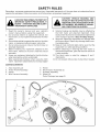
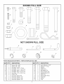
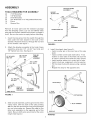
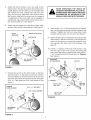
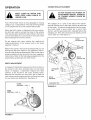
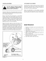
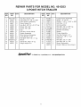
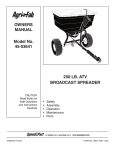
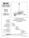
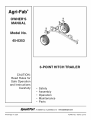
Agri-Fab ®
OWNER'S
MANUAL
Model
No.
45-0353
3-POINT
CAUTION:
Read Rules for
Safe Operation
and Instructions
Carefully
•
•
•
•
•
HITCH TRAILER
Safety
Assembly
Operation
Maintenance
Parts
www.speedepart.com
PRINTED
IN USA
FORM NO. 48975 (2/04)
SAFETY
RULES
Remember, any power equipment can cause injury if operated improperly or if the user does not understand
operate the equipment. Exercise caution at all times when using power equipment.
&
IMPORTANT SAFETY PRECAUTIONS. IT
MEANS
- ATTENTION!
BECOME
ALERT!
LOOK FOR
THIS SYMBOL
TO POINT
OUT
YOUR SAFETY IS INVOLVED.
1.
2.
3.
4.
5.
6.
7.
Read this owner's manual and your vehicle's
owner's manual before using this equipment.
Do not allow children to operate the vehicle, the
hitch trailer, or any implement attached to the hitch
trailer.
Do not allow adults to operate the vehicle, the hitch
trailer, or implement without proper instruction.
Do not allow anyone to ride on the hitch trailer or
attached implement.
Before lowering any implement attached to the
hitch trailer, make sure no one is near the area of
operation.
Lower any implement attached to the hitch trailer
when leaving the vehicle unattended.
Wear appropriate footwear when using the hitch
trailer. Implement attachments
have sharp edges!
8.
9.
10.
11.
12.
13.
CAUTION:
VEHICLE
BRAKING AND
STABILITY MAY BE AFFECTED BYTHE
ADDITION OFAN ACCESSORY
OR AN
ATTACHMENT. BE AWARE OF CHANGING CONDITIONS ON SLOPES.
Vehicle braking and stability may be affected by
the hitch trailer and attached implement.
Drive
slowly when hitch trailer and attached implement is
in the transport position. Stay off steep slopes.
Stop and inspect the equipment for damage after
striking an object. Repair any damage before continuing operation.
Keep all nuts and bolts tight and be sure that the
equipment is in safe operating condition.
Before attaching or removing the hitch trailer or
associated implement, park and lock tow vehicle in
a safe condition.
This hitch trailer is rated for category 0 and 1
implements.
Do not exceed 400 pounds of attachment weight.
CARTONCONTENTS
1.
2.
3.
Axle Assembly (2)
Trailer Frame Assembly
Switch
4.
Wire Harness
Assembly
5.
6.
7.
8.
how to
Winch
Hitch Anchor Assembly (2)
Drawbar Assembly
Wheel (2)
Parts Package (see page 3)
4
SHOWN
FULL SIZE
F
H
/
M
I
I
---
/
CCP
/
O
/
NOT SHOWN
FULL SIZE
R
/
/
/s
U
_O
V
t
0
W
X
PARTS PACKAGE
KEY
A
B
C
D
E
F
G
H
I
J
K
L
QTY.
1
1
2
3
1
4
2
2
1
3
5
2
CONTENTS
- PARTS SHOWN ACTUAL
DESCRIPTION
Screw, #8 x 3/8"
Screw, #6 x 3/4"
Hex Bolt, 5/16" x 1" Lg.
Hex Bolt, 1/4" x 1-3/4" Lg.
Hex Bolt, 3/8" x 1-3/4" Lg.
Hex Bolt, 3/8" x 2-1/2" Lg.
Hex Bolt, 1/2" x 2-3/4" Lg.
Clevis Pin
Hex Nut, Nylock #6
Hex Nut, Nylock, 1/4"
Hex Nut, Nylock, 3/8"
Hex Nut, Nylock, 1/2"
SIZE
KEY
M
N
0
P
Q
R
S
T
U
V
W
X
QTY.
2
4
1
4
7
2
2
1
3
2
1
2
DESCRIPTION
Lock Washer, 5/16"
Washer, 1" Flat
Spacer
Cotter Pin
Haircotter Pin
Quick Attach Pin
Height Adjust Pin
Hitch Pin
Reclosable
Hub Cap
Pulley
Clip
Strap
ASSEMBLY
TOOLS
TRAILER
FRAME
ASSEMBLY
REQUIRED
FOR ASSEMBLY
7/1 6" Wrenches
1/2" Wrenches
9/1 6" Wrenches
3/4" Wrenches or 10" Adjustable
Pliers
Grease Gun
(2)
(1)
(2)
(2)
(1)
(1)
HEIGHT
ADJUST
/
Wrenches
/
/
/
Remove all loose parts and the hardware package
from the shipping carton. Lay out and identify each
part and the common hardware as shown on pages 2
and 3. Be sure the carton is empty before discarding.
Insert the long wires from the switch through the
hole under the hitch bracket in the side of the
drawbar. Route the wires out through the rear end
of the drawbar. See figure 1.
1 .
2.
Attach the drawbar assembly to the trailer frame
assembly using two 1/2" x 2-3/4" hex bolts and
1/2" Nylock hex nuts. See figure 1.
112" x 2-314"
HEX BOLT
1/2" NYLOCK
TRAILER
FRAME
HEX
.UT
HEX BOLT
112" x 2-3/4"
l
PIN
HAIRCOTTER
iJ
PIN
AXLE
ASSEMBLY
/
AXLE SHAFT
FIGURE 2
4.
Install the wheels (see figure 3):
• Install a cotter pin in the inner hole of the axle
shaft.
• Install a wheel on the axle shaft with a 1" flat
washer on each side of the wheel. Be sure the
air stem is toward the outside for easy access.
• Install another cotter pin in outer hole of axle.
• Install a hub cap, snapping it onto the washer.
• Fill the wheel hubs with grease using a grease
gun.
• Repeat this step for the opposite axle.
112" NYLOCK
HEX NUT
'_
AXLE
HOLE
IN
SIDE OF
DRAWBAR
WIRE
FIGURE
SHAFT
DRAWBAR
ASSEMBLY
DETAIL
1" FLAT
WASHER
1
-_
COTTER
PINS
/
.
Slide an axle assembly up through one end of the
trailer frame, with the shaft of the axle pointing
out. Pin the axle to the frame using a height adjust
pin and a haircotter pin. Repeat this step for the
other axle assembly on the opposite end of the
trailer. Be sure both axles are pinned at the same
height. See figure 2.
1" FLAT
HUB CAP
FIGURE 3
WHEEL
WASHER
.
Install
the hitch
anchors
onto
the ends
of the
trailer frame. The clevis pin hole should be to the
inside. Secure with four 3/8" x 2-1/2" hex bolts and
.
Install a quick attach pin in the slot of each hitch
anchor. Secure with a haircotter pin. See figure 4.
.
HITCH
QUICK
ANCHOBB
_Z
3/8" x 2-
CLEVIS
ATTACH
PIN
PIN
.
_/
HEX BOLTS
HAIBCOTTER
PINS
HANDLINGTHEWIRE ROPE, FOLLOWALL
WHEN OPERATING
INSTRUCTIONS
AND SAFETY
THE WINCH
RELATED
OR
INFORMATION
AS DETAILED IN THE
MANUALS INCLUDED WITH THEWINCH.
_
3/8" Nylock hex nuts. Tighten the nuts only until
they are just snug. Slide each hitch anchor along
the frame to align with the outer hole for category
1 implements or the inner hole are for category 0
implements. Secure each hitch anchor with a clevis
pin and haircotter pin. See figure 4.
Install three 1/4" x 1-3/4" hex bolts and 1/4" Nylock
hex nuts through the pulley bracket welded to the
drawbar. Tighten the nuts, but leave them loose
enough that the bolts can still spin. See figure 6.
Set the winch drum to "freewheel" according to the
instructions in the winch manual. Pull enough wire
rope from the drum to extend the hooked end of
the rope past the hitch end of the drawbar. See
figure 6.
10. Install a 1" spacer in the hub of the pulley. Loop
the wire rope under and around the pulley and
then install the pulley in the bracket using a 3/8" x
1-3/4" hex bolt and a 3/8" Nylock hex nut. Tighten.
See figure 6.
318" NYLOCK
HEX NUTS
HOOK END
OF WIRE ROPE
FIGURE4
7.
PULLEY
318" NYLOCK
HEX NUT
Position the winch on the hitch trailer so that the
tension plate is on the back of the winch and the
wire rope feeds out from the bottom of the drum at
the front. Secure the winch to the trailer using two
5/16" x 1" hex bolts and 5/16" lock washers. See
figure 5.
1"SPACER
/o
/
-'/"_1/4"
NYLOCK
HEX
TENSION
PLATE AT REAR
5116" x 1" HEX BOLT
5/16"
LOCK
WASHER
;/
FIGURE 6
ALTERNATE
MODELS
FIGURE 5
NUT
ELECTRICAL
CONNECTIONS
FOR THE WINCH BEFORE
REFER
TO THE
INSTRUCTION
ELECTRICAL
CONNECTIONS.
1.
Connect
the wires
in the drawbar
and black to
NOTE: tf the winch terminals are not marked
and negative, you will need to check the
of rotation after you complete the wiring
Reverse the winch hookup if the cable
when it should wind out.
positive
direction
hookup.
winds in
NOTE: The reclosable straps can be used instead
of the clips for attaching the switch and quick
connector to the vehicle.
5.
Attach a clip to the switch using a #8 x 3/8"
screw. The switch can be attached at the front
or rear of the vehicle.
6.
Connect the quick connectors
and the wire harness.
7,
2.
Connect the trailer to the vehicle hitch using the
trailer hitch pin and a hair cotter pin.
.
Connect the wire harness to the vehicle battery.
Secure the red wire to the positive terminal and
the black wire to the negative terminal. See figure
7.
SWITCH
Route the wire harness from the battery to the
rear of the vehicle. Be sure the wires are clear
of any moving parts, hot engine parts, or pinch
points. Attach a clip to the quick connector on
the wire harness using a #6 x 3/4" screw and a
nylock nut. Clip the quick connector to the rear
rack. See figure 8.
MAKING
MANUAL
to the winch
terminals,
securing red to positive
negative. See figure 7.
4,
Check the direction of winch rotation. The cable
should unwind when the "rope out" button is
pushed. If the cable winds onto the winch instead of unwinding, check the battery harness.
Red should connect to positive and black to
negative. If the wire harness is correct, reverse
the wires connected to the winch.
QUICK
CONNECTOR
#6 X 3/4"
l_J
SCREW
f__
__'
_
f
BLACK
RED
RED
+
--
POSITIVE
"HOT"
BATTER_
FIGURE 7
WINCH
MOTOR
CLIP
NYLOCK
QUICK
CONNECTOR
for the switch
FIGURE 8
NUT
SWITCH
#8x 3/8"
SCREW
OPERATION
,_
CONNECTING
WIRE ROPE WHEN WINCH
IS
KEEP CLEAR
OF WINCH AND
UNDER LOAD.
The 3-Point Hitch Trailer is only designed for towing
category 0 or 1 attachments.
The total working weight
of any attachment must not exceed 400 pounds.
When the hitch trailer is attached to the tow vehicle,
the hitch pin used to connect the trailer to the vehicle
hitch must be secured with the haircotter pin. Failure to
use the haircotter pin could result in the hitch trailer
disconnecting
from the tow vehicle.
&
ATTACHMENT
DO NOT EXCEED 400 POUNDS OF
ATTACHMENT
WEIGHT. STABILITY
OF TOWING VEHICLE
COULD BE
AFFECTED.
The category 0 or 1 pins on the sides of the attachment fit into the slots in the hitch anchors at each end
of the trailer. To secure the attachment to the trailer,
you must install a quick attach pin in each hitch
anchor, with the quick attach pin installed behind the
category pin. Then secure each quick attach pin with
a hair cotter pin. See figure 10.
QUICK
ATTACH
PIN
Do not operate this trailer without first reading the
safety precautions
in this manual and in the winch
operator's manual.
Refer to the owner's manual of the attachment you are
towing with the hitch trailer for the operation instructions for that particular attachment. Refer to the user's
guide provided with the winch for the winch operation
instructions.
Refer to the following paragraphs for the
adjustments
pertaining to the hitch trailer.
QUICK
ATTACH
WIDTH ADJUSTMENT
A category 0 attachment requires the hitch anchors to
be moved to the inner locating holes on the trailer
frame. A category
1 attachment
requires the hitch
anchors to be moved to the outer locating holes.
Remove the haircotter pin and clevis pin to slide the
hitch anchors to the proper position on the trailer frame
for your particular attachment.
See figure 9.
OUTER
POSITION
INNER
POSITION
FIGURE 9
-- CAT.
0
PIN
HITCH
ANCHOR
CATEGORY
--
CAT.
1
FIGURE
10
PIN
PIN
LEVELING
ADJUSTMENT
ATTACHMENTADJUSTMENT
Use the switch on the tow vehicle
WITH ATTACHMENT
RAISED!
PERDO NOTINJURY
ADJUST
SONAL
CANTRAILER
RESULT. HEIGHT
_
The trailer height must be adjusted after the trailer is
attached to the vehicle to obtain the best performance
out an attached implement.
to raise or lower the
attachment. Push the "rope in" button on the switch to
raise the attachment.
Push the "rope out" button on
the switch to lower the attachment.
When the attachment
is in the lowered, operating
position, there should be slack in the wire rope allowing the implement to follow the contour of the ground.
Holes in the trailer frame provide for a 1-inch height
change. Holes in the axle assembly provide for a 2inch height change. From the lowest setting, the trailer
height can be raised 11 inches. Remove the haircotter
pin to remove the height adjust pin. Install the pin in
the upper or lower hole of the trailer frame and the
appropriate hole of the axle assembly.
Adjust the trailer height so that the frame of the
attached implement is horizontal during operation.
If
the implement will penetrate below ground level during operation,
adjust the trailer height so that the
implement is level while above ground and then lower
the trailer a distance equal to the approximate operating depth of the implement.
Make sure the axle assemblies are set at the same height. See figure 11.
MAINTENANCE
1.
Check for and tighten any loose hardware
each use.
2.
Lubricate both wheel axles with grease before use
each season.
Inspect wire cable on winch before each use and
replace cable if necessary.
Refer to user's guide provided with winch for
winch maintenance.
3.
4.
5.
6.
ADJUST OPERATING
POSITION
OF
ATTACHMENT
BY
MOVING
AXLE
ASSEMBLY
UP
OR DOWN
GROUND
OPERATING
DEPTH
FIGURE
11
SURFACE
ATTACHMENT
FRAME
LEVEL DURING OPERATION
before
Remove all dirt and rust. Touch up paint before
placing hitch trailer in storage.
Store hitch trailer inside a dry area.
NOTES
REPAIR
PARTS
FOR
3-POINT
MODEL
HITCH
NO.
45-0353
TRAILER
/
6,7
_J 8
J
%9
\\2
22
J
J
1
J
21
J
/
J
J
J
J
16
18
20
19
J
J
\
\f
\
2
22
/
26
18
\
27
24
• _
1
27
29
32
\
2
19
20
10
REPAIR PARTS FOR MODEL NO. 45-0353
3-POINT HITCH TRAILER
REF.
NO.
PART
NO.
QTY.
1
2
3
4
5
6
7
8
9
10
11
12
13
14
15
16
HA21362
43343
64778
48967
43432
49383
49385
47397
49384
65040
65039
43086
43063
WW2000V12
43513
23353
5
7
2
2
4
1
1
2
1
1
1
2
2
1
2
2
DESCRIPTION
REF.
NO.
PART
NO.
QTY.
Hex Nut, Nylock, 3/8"
Haircotter Pin, 1/8" x 2-3/8"
Hitch Anchor Assembly
Quick Attach Pin
Hex Bolt, 3/8"-16 x 2-1/2" Lg.
Screw, #6 x 3/4"
Screw, #8 x 3/8"
Clip
Hex Nut, Nylock #6-32
Switch Assembly
Wire Harness Assembly
Lock Washer, 5/16"
Hex Bolt, 5/16"-18 x 1" Lg.
Winch
17
18
19
20
21
22
23
24
25
26
27
28
29
30
64769
48965
43601
43014
64770
43510
712-3083
64792
24286
48980
47189
43093
46065
1509-69
1
2
4
2
2
2
2
1
1
1
3
4
1
3
Clevis Pin, 3/8" x 3" Lg.
Height Adjust Pin
31
32
41576
49232
48975
1
3
1
SpeedEPart the
... to
11
p..t
DESCRIPTION
Trailer Frame Assembly
Wheel, 15" x 6.00
Washer, 1.59" x 1.032" x .060'
Hub Cap, 1-1/2"
Axle Assembly
Hex Bolt, 1/2" x 2-3/4" Lg.
Hex Nut, Nylock, 1/2"
Drawbar Assembly
Spacer
Pulley Assembly
Hex Nut, Nylock, 1/4"
Cotter Pin, 1/8" x 1-1/2"
Hitch Pin
Hex Bolt, 1/4" x 1-3/4"
Hex Bolt, 3/8" x 1-3/4"
Strap, Reclosable
Owner's Manual (not shown)
www.speedepart.com
© 2004Agri-Fab,Inc.
REPAIRPARTS
Agri-Fab,Inc.
303 WestRaymond
Sullivan,IL61951
217-728-8388
www.agri-fab.com