1
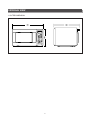
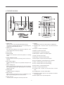
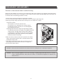
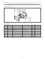
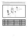
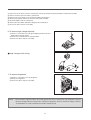
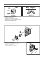
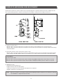
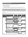
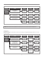
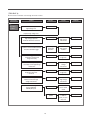
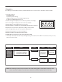
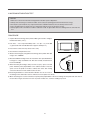
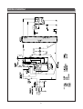
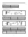
S/M No.: R63XQ0S001
Service Manual
Microwave Oven
Model : KOR-63XQ0S
✔ Caution
: In this Manual, some parts can be changed for improving, their
performance without notice in the parts list. So, if you need the
latest parts information,please refer to PPL(Parts Price List) in
Service Information Center (http://svc.dwe.co.kr).
DAEWOO ELECTRONICS CO., LTD.
http://svc.dwe.co.kr
PRECAUTIONS TO BE OBSERVED BEFORE AND
DURING SERVICING TO AVOID POSSIBLE
EXPOSURE TO EXCESSIVE MICROWAVE ENERGY
(a) Do not operate or allow the oven to be operated with the door open.
(b) Make the following safety checks on all ovens to be serviced before activating the magentron or other microwave
source, and make repairs as necessary: (1) Interlock operation, (2) proper door closing, (3) Seal and sealing
surfaces (arcing, wear, and other damage), (4) Damage to or loosening of hinges and latches, (5) Evidence of
dropping or abuse.
(c) Before turning on power to the microwave oven for any service test or inspection within the microwave generating
compartments, check the magnetron, wave guide or transmission line, and cavity for proper alignment, integrity,
and connections.
(d) Any defective or misadjusted components in the interlock, monitor, door seal, and microwave generation and
transmission systems shall be repaired, replaced, or adjusted by procedures described in this manual before the
oven is released to the owner.
(e) A microwave leakage check to verify compliance with the Federal performance standard should be performed on
each oven prior to release to the owner.
TABLE OF CONTENTS
SAFETY AND PRECAUTIONS
1. FOR SAFE OPERATION
2. FOR SAFE SERVICE PROCEDURES
2
2
2
SPECIFICATIONS
3
EXTERNAL VIEW
1. OUTER DIMENSION
2. FEATURE DIAGRAM
3. CONTROL PANEL
4
4
5
6
INSTALLATION
8
OPERATIONS AND FUNCTIONS
9
DISASSEMBLY AND ASSEMBLY
10
INTERLOCK MECHANISM AND ADJUSTMENT
17
TROUBLE SHOOTING GUIDE
18
MEASUREMENT AND TEST
1. MEASUREMENT OF THE MICROWAVE POWER OUTPUT
2. MICROWAVE RADIATION TEST
3. COMPONENT TEST PROCEDURE
22
22
23
24
WIRING DIAGRAM
25
PRINTED CIRCUIT BOARD
1. CIRUCIT CHECK PROCECDURE
2. PCB CIRCUIT DIAGRAM
3. P.C.B. LOCATION NO
26
26
29
30
EXPLODED VIEW AND PARTS LIST
1. DOOR ASSEMBLY
2. CONTROL PANEL ASSEMBLY
3. TOTAL ASSEMBLY
32
32
32
32
1
SAFETY AND PRECAUTIONS
1. FOR SAFE OPERATION
Damage that allows the microwave energy (that cooks or heats the food) to escape will result in poor cooking and may cause
serious bodily injury to the operator.
IF ANY OF THE FOLLOWING CONDITIONS EXIST, OPERATOR MUST NOT USE THE APPLIANCE.
(only a trained service personnel should make repairs.)
(1) A broken door hinge.
(2) A broken door viewing screen.
(3) A broken front panel, oven cavity.
(4) A loosened door lock.
(5) A broken door lock.
The door gasket plate and oven cavity surface should be kept clean.
No grease, soil or spatter should be allowed to build up on these surfaces or inside the oven.
DO NOT ATTEMPT TO OPERATE THIS APPLIANCE WITH THE DOOR OPEN.
The microwave oven has concealed switches to make sure the power is turned off when the door is opened.
Do not attempt to defeat them.
DO NOT ATTEMPT TO SERVICE THIS APPLIANCE UNTIL YOU HAVE READ THIS SERVICE MANUAL.
2. FOR SAFE SERVICE PROCEDURES.
1. If the oven is operative prior to servicing, a microwave emission check should be performed prior to servicing the oven.
2. If any certified oven unit is found to servicing, a microwave emission check should be performed prior to servicing the oven.
(1) inform the manufacturer, importer or assembler,
(2) repair the unit at no cost to the owner,
(3) attempt to ascertain the cause of the excessive leakage,
(4) tell the owner of the unit not to use the unit until the oven has been brought into compliance.
3. If the oven operates with the door open, the service person should tell the user not to operate the oven and contact the
manufacturer immediately.
IMPORTANT
The wire in this mains lead coloured in accordance with the following code.
Green-and-yellow
:Earth
Blue
:Neutral
Brown
:Live
As the colours of the wires in the mains lead of this appliance may not correspond with the coloured markings identifying the
terminals in your plug, proceed as follows:
The wire which is coloured green-and-yellow must be connected to the terminal in the plug which is marked with the letter
‘E’, earth symbol or coloured green-and-yellow.
The wire which is coloured blue must be connected to the terminal which is marked with the letter ‘N’ or coloured black.
The wire which is coloured brown must be connected to the terminal which is marked with the letter ‘L’ or coloured red.
NOTE : This oven is designed for counter-top use only.
2
SPECIFICATIONS
MODEL
KOR-63XQ
POWER SUPPLY
230V~50Hz SINGLE PHASE WITH EARTHING
POWER
CONSUMPTION
MICROWAVE
1200W
GRILL
COMBINATION
MICROWAVE ENERGY OUTPUT
800W
MICROWAVE FREQUENCY
2450MHz
OUTSIDE DIMENSIONS (W×H×D)
465×279×352 mm (18.3×11.0×13.9 in.)
CAVITY DIMENSIONS (W×H×D)
290×220×290 mm (11.4×8.7×11.4 in.)
NET WEIGHT
APPROX. 13Kg(28.7 lbs.)
TIMER
59 min. 99 sec
FUNCTION SELECTIONS
MICROWAVE
POWER SELECTIONS
10 LEVELS
CAVITY VOLUME
0.7 Cu. Ft
♣ SPECIFICATIONS ARE SUBJECT TO CHANGE WITHOUT NOTICE.
3
EXTERNAL VIEW
1. OUTER DIMENSION
STAGE
1
2
LOCK
NO
DEFROST
WEIGHT TIME
CUP
Auto Cook
AUTO
START
g
Menu
1. Raked Potato
2, Fresh Vegetable
3. Soup
4. Fish Fillets
5. Meat Loaf
Weight
Auto Def.
Dinner
Plate
Frozen
Pizza
Muffin
Beverage
popcorn
Feeding
Bottle
Speedy Cook
1
4
7
Clock / A.Start
Stop/Clear
2
5
8
0
3
6
9
Power
Start
4
2. FEATURE DIAGRAM
1. DOOR latch
When the door is closed it will automatically shut off.
If the door is opened while the oven is operating. The
magnetron will automatically shut off.
11. Display
Cooking time, power level, present time are displayed.
12. Speedy cook - Touch to set the any desired reheat
setting.
2. DOOR seal
The door seal maintains the microwave within the oven
cavity and prevents microwave leakage.
13. Popcorn - Used to cook popcorn.
14. Muffin - Used to cook muffin.
3. Oven cavity.
15. Baked potato - Used to baked potato.
4. Spatter shield
Protects the microwave outlet from splashes of cooking
foods.
16. Dinner plate - Used to reheat dinner plate.
5. Safety interlock system
Prevents the oven from operating while the door is
opened.
18. Beverage - Used to reheat beverage.
17. Soup - Used to reheat soup.
19. Frozen pizza - Used to reheat frozen pizza.
20. Fresh vegetable - Used to blanch fresh vegetable.
6. Door release button
Pushing this button stops oven operation and opens the
door.
21. More - Used to add on one touch cooking
22. Less - Used to remove one touch cooking.
7. Glass cooking tray
Made of special heat resistant glass. The tray must always
be in proper position before operating. Do not cook food
directly on the tray.
23. Auto defrost - Used to defrost foods.
24. Power - Used to set power level.
25. Clock/A. start - Used to set clock & Used to set auto
start.
8. Roller guide
Supports the glass cooking tray.
26. Feeding bottle - Used to sterilize bottle.
9. Door screen
Allows viewing of food. The screen is designed so that
light can pass through, but not the microwaves.
27. Stop/Clear- Used to stop the oven operation or to delete
the cooking data.
28. Start- Used to start a selected operation.
10. Time set pad
Used to set the cooking time and the present time.
5
INSTALLATION
1. Steady, flat location
This microwave oven should be set on a steady, flat surface
This microwave oven is designed for counter top use only.
2. Leave space behind and side
All air vents should be kept a clearance. If all vents are covered during operation, the oven may overheat and, eventually,
cause failure.
3. Away from Radio and TV sets
Poor television reception and radio interference may result if the oven is located close to a TV, Radio, antenna or feeder and so on.
Position the oven as far from them as possible.
4. Away from heating appliances and water taps
Keep the oven away from hot air, steam or splash when choosing a place to position it, or the insulation might be adversely
affected and breakdowns occur.
5. Power supply
Check your local power source. This microwave oven requires a current of approximately 6 amperes, 230V, 50Hz
Power supply cord is about 0.8 meters long.
The voltage used must be the same as specified on this oven. Using a higher voltage may result in a fire or other accident
causing oven damage. Using low voltage will cause slow cooking. We are not responsible for damage resulting from use of
this oven with a voltage of ampere fuse other than those specified.
This appliance is supplied with cable of special type, which, if damaged, must be repaired with cable of same type.
Such a cable can be purchased from DAEWOO and must be installed by a Qualified Person.
6. Examine the oven after unpacking for any damage such as:
A misaligned door, broken door or a dent in cavity.
If any of the above are visible, DO NOT INSTALL, and notify dealer immediately.
7. Do not operate the oven if it is colder than room temperature.
(This may occur during delivery in cold weather.) Allow the oven to become room temperature before operating.
EARTHING INSTRUCTIONS
This appliance must be earthed. In the event of an electrical short circuit, earthing reduces the risk of the electric shock by
providing an escape wire for the electric current. This appliance is equipped with a cord having a earthing wire with a earthing
plug. The plug must be plugged into an outlet that is propely installed and earthed.
WARNING
Improper use of the earthing plug can result in a risk of electric shock.
Consult a qualified electrician or serviceman if the earthing instructions are not completely understood, or if doubt exists as
to whether the appliance is properly earthed, and either.
If it is necessary to use an extension cord, use only a 3-wire extension cord that has a 3-blade earthing plug, and a 3-slot
receptacle that will accept the plug on the appliance.
The marked rating of the extension cord should be equal to or greater than the electrical rating of the appliance, or Do not
use an extension cord.
6
OPERATIONS AND FUNCTIONS
1. Connect the main lead to an electrical outlet.
2. After placing the food in a suitable container, open the oven door and put it on the glass tray. The glass tray must always be in
place during cooking.
3. Close the door securely.
4. When the oven door is opened, the light turns off.
5. The oven door can be opened at any time during operation by touching the door release button on the control panel.
The oven will automatically shut off. To restart the oven, close the door and then touch START.
6. Each time a pad is touched, a BEEP will sound to acknowledge the touch.
7. The oven automatically cook on full power unless set to a lower power level.
8. The display will show : 0 when the oven is plugged in.
9. Time clock returns to the present time when the cooking time ends.
10. When the STOP/CLEAR pad is touched during the oven operation, the oven stops cooking and all information retained.
To erase all information(except the present time), touch the STOP/CLEAR pad once more. If the oven door is opened during
the oven operation, all informaiton is retained.
11. If the START pad is touched and the oven does not operate, check the area between the door and door is closed securely.
The oven will not start cooking under the door is completely closed or the program has been reset.
Make sure the oven is properly installed and plugged into the electrical outlet.
Wattage output chart
The power level is set by pressing the Power pad. The chart shows the display, the power level and the percentage of power.
Touch Power pad,
Once the touch
Power Level (Display)
Approximate Percentage of Power
POWER
P-HI
100%
9
P-90
90%
8
P-80
80%
7
P-70
70%
6
P-60
60%
5
P-50
50%
4
P-40
40%
3
P-30
30%
2
P-20
20%
1
P-10
10%
0
P-00
0%
7
DISASSEMBLY AND ASSEMBLY
Cautions to be observed when trouble shooting.
Unlike many other appliances, the microwave oven is high-voltage, high-current equipment. It is completely safety during normal
operation. However, carelessness in servicing the oven can result in an electric shock or possible danger from a short circuit. You
are asked to observe the following precautions carefully.
1. Always remove the power plug from the outlet before servicing.
2. Use an insulated screwdriver and ware rubber gloves when servicing the high voltage side.
3. Discharge the high voltage capacitor before touching any oven components or wiring.
(1) Check the earthed.
Do not operate on a two-wire extension cord.
The microwave oven is designed to be used with earthed.
It is imperative, therefore, to make sure it is earthed properly
before beginning repair work.
(2) Warning about the electric charge in the high voltage capacitor.
For about 30 seconds after the operation has stopped and electric
charge remains in the high voltage capacitor. When replacing
or checking parts, short between oven chassis and the negative
high terminal of the high voltage capacitor, by using a properly
insulated screwdriver to discharge.
4. When the 12A fuse is blown out due to the operation of the monitor
switch, replace primary interlock switch, secondary interlock switch
and interlock monitor switch.
5. After repair or replacement of parts, make sure that the screws are
properly tightened, and all electrical connections are tightened.
6. Do not operate without cabinet.
CAUTION : Service personnel should remove their watches whenever working close to or replacing the magnetron.
WARNING : When servicing the appliance, need a care of touching or replacing high potential parts because of electrical
shock or exposing microwave. These parts are as follows - HV Transformer, Magnetron, HV Capacitor, HV
Diode. HV Fuse.
8
1. To remove cabinet
1) Remove three screws on cabinet back.
2) Push the cabinet backward.
2. To remove door assembly
1) Remove a screws which secure the stopper hinge top.
2) Remove the door assembly from top plate of cavity.
3) Reverse the above for reassembly.
NOTE : After replacing the door assembly, perform a check of correct
alignment with the hinge and cavity front plate.
9
✔ Caution: In this Service Manual, some parts can be changed for improving, their performance without notice in the parts list. So, if you need the
latest parts information, please refer to PPL(Parts Price List) in Service information Center(http://svc.dwe.co.kr)
3. To remove door parts.
(1) KOR-63XQ0S
REF.NO
PART CODE
A01
3512202030
FRAME DOOR
ABS SG-175, SG-0760D
1
A02
3517006180
BARRIER-SCREEN O
SAN
1
A03
3515304610
SUPPORTER BARR-S O
PP
1
A04
3515204100
STOPPER HINGE T AS
KOR-63150S
1
A05
3511705500
DOOR WELD AS
KOR-61150S
1
A06
3517002800
BARRIER-SCREEN * I
POLYESTER TO. 1
1
A07
3512300210
GASKET DOOR
PP
1
A08
3513100700
HOOK
POM
1
A09
3515101300
SPRING HOOK
PW1
1
DESCRIPTION
PART NAME
10
Q’TY
REMARK
(1) Remove the gasket door from door plate.
(2) Remove the barrier screen inner from door plate.
(3) Remove the door frame from door plate.
(4) Remove the stopper hinge top from door plate.
(5) Remove the spring and the hook.
(6) Remove the supporter barrier screen outer from door frame.
(7) Remove the barrier screen outer from door frame.
(8) Reverse the above steps for reassembly.
4. Method to reduce the gap between the door seal and
the oven front surface.
A
(1) To reduce gap located on part ‘A’.
Loosen a screw on stopper hinge top, and then push the door
to contact the door seal to oven front surface.
Tighten a screw.
(1) To reduce gap located on part ‘B’.
Loosen two screws on stopper hinge under, and then push the
door to contact the door seal to oven front surface.
Tighten two screws.
B
NOTE : A small gap may be acceptable if the microwave leakage does not exceed 4mW/cm2.
11
✔ Caution: In this Service Manual, some parts can be changed for improving, their performance without notice in the parts list. So, if you need the
latest parts information, please refer to PPL(Parts Price List) in Service information Center(http://svc.dwe.co.kr)
5. To remove control panel parts.
(1) KOR-63XQ0S
REF.NO
PART CODE
PART NAME
B01
3518519700
SWITCH MEMBRANE
KOR-618Q0S
1
B02
3516710740
CONTROL PANEL
ABS SG-175, SG-0760D
1
B03
PKMPMSCY00
PCB MAIN AS
KOR-63XQ0S
1
B04
7122401211
SCREW TAPPING
T2S TRS 4 12 MFZN
3
B05
3513701420
LEVER DOOR OPEN
PP
1
B06
441G430171
SPRING BUTTON
SWP
1
B07
3516904430
BUTTON DOOR OPEN
ABS SG-175, SG-0760D
1
DESCRIPTION
12
Q’TY
REMARK
(1) Remove the screw which secure the control panel, push up two snap fits and draw forward the control panel assembly.
(2) Remove the door open lever from the control panel.
(3) Remove four screws which secure the PCB assembly to control panel.
(4) Disconnect membrane tail from the connector of the PCB assembly.
(5) Detach membrane from the control panel.
(6) Remove door open button and button spring from the control panel.
(7) Reverse the above steps for reassembly.
6. To remove high voltage capacitor.
1) Remove a screw which secure the grounding ring terminal of the H.V.
diode and the capacitor holder.
2) Remove the H.V. diode from the capacitor holder.
3) Reverse the above steps for reassembly.
◆ High voltage circuit wiring
7. To remove magnetron.
1) Remove a screw which secure the magnetron.
2) Remove the magnetron.
3) Reverse the above steps for reassembly.
NOTE : Never install the magnetron without the metallic gasket plate which is packed with each magnetron to prevent
microwave leakage. Whenever repair work is carried out on magnetron, check the microwave leakage. It shall not
exceed 4mW/cm2 for a fully assembled oven with door normally closed.
13
8. To remove wind guide assembly.
1) Remove a screw for earthing.
2) Remove the noise filter from the wind guide.
3) Remove a screw which secure the wind guide assembly.
4) Draw forward the wind guide assembly.
5) Pull the fan from the motor shaft.
6) Remove two screws which secure the motor shaded pole.
7) Remove the motor shaded pole.
8) Reverse the above steps for reassembly.
9. To remove H.V.transformer.
1) Remove four screws holding the H.V.transformer.
2) Remove the H.V.transformer.
3) Reverse the above steps for reassembly.
14
INTERLOCK MECHANISM AND ADJUSTMENT
The door lock mechanism is a device which has been specially designed to completely eliminate microwave radiation when the
door is opened during operation, and thus to perfectly prevent the danger resulting from the leakage of microwave.
(1) Primary interlock switch
When the door is closed, the hook locks the oven door. If the door is not closed properly. the oven will not operate.
When the door is closed, the hook pushes the button of the microswitch. Then the button of the primary interlock switch bring it
under ON condition.
(2) Secondary interlock switch and interlock monitor switch
When the door is closed, the hook pushes the lock lever downward. The lock lever presses the button of the interlock monitor
switch to bring it under NO condition and presses the button of the secondary interlock switch to bring it under ON condition.
ADJUSTMENT
Interlock monitor switch
When the door is closed, the interlock monitor switch should be changed(NO condition) before other switches are closed.
When the door is opened, the interlock monitor switch should be chanded(NC condition) after other switches are opened.
(3) Adjustment steps
a) Loosen the one mounting screw.
b) Adjust interlock switch assembly position.
c) Make sure that lock lever moves smoothly after adjustment is completed.
d) Tighten completely one mounting screw.
NOTE : Microwave emission test should be performed after adjusting interlock mechanism. If the microwave emission
exceed 4mW/cm2, readjust interlock mechanism.
15
TROUBLE SHOOTING GUIDE
Following the procedure below to check if the oven is defective or not.
1) Check earthing before trouble checking.
2) Be careful of the high voltage circuit.
3) Discharge the high voltage capacitor.
4) When checking the continuity of the switches, fuse or high voltage transformer, disconnect one load wire from these parts and
check continuity with the AC plug removed. To do otherwise may result in a false reading or damage to your meter.
NOTE : When electric parts are checked, be sure the power cord is not inserted the wall outlet.
Check wire harness, wiring and connected of the terminals and power cord before check the parts listed below.
(TROUBLE 1)
Oven does not operate at all : any inputs can not be accepted.
CONDITION
Fuse blows.
CHECK
RESULT
Check continuity of
interlock monitor switch with
door closed
(COM↔NC)
Continuity
CAUSE
REMEDY
Malfunction of
Interlock
monitor switch
Replace
Malfunction of
Interlock
switch
Replace
Shorted contacts
of primary
interlock switch
Replace
Defective low
voltage
transformer
Replace
Defective
high voltage
transformer
Replace
NOTE 1
No continuity
Check continuity of
both primary and secondary
interlock switch with door closed
NO
Continuity
NOTE 1
Continuity
Check continuity of
Primary interlock switch contact
with door partially open until
interlock monitor switch contact
close
(COM<->NO)
Continuity
Check continuity of
Primary winding of low voltage
transformer
0Ωor infinite
Approx.
530~ 310
(normal)
Disconnect high voltage
fuse and operate the unit
Fuse again
blows
16
NOTE 1
CONDITION
CHECK
RESULT
CAUSE
REMEDY
Outlet has
proper voltage
Fuse does not
blow?
Check continuity of
magnetron
No
continuity
Defective
magnetron
Replace
Check continuity of
noise filter board
No
continuity
Defective line
filter board
Replace
Check continuity of
power supply cord
No
continuity
Open power
supply cord
Replace
Normal
Defective touch
control circuit
Adjust
NOTE : All these switches must be replaced at the same time, please refer to “Interlock mechanism And Adjustment.”
(TROUBLE 2)
Display shows all figures selected, but oven does not start cooking, even though desired program and time are set and
start pad is tapped.
CONDITION
CHECK
RESULT
CAUSE
REMEDY
Turn table
motor and
oven lamp
do not turn on
Check continuity of
primary interlock switch
No
continuity
Malfunction of
primary interlock
switch
Adjust or
replace
Check continuity of
secondary interlock
and D.O.M switches
No
continuity
Malfunction of
secondary
interlock and
D.O.M. switch
Adjust or
replace
Check D.C. voltage
being supplied to
RELAY(RY2) coil
0V
Approx.
15VDC
17
Defective touch
control circuit
Fault contacts
of RELAY
(RY2) or open
relay coil
Replace
Replace
(TROUBLE 3)
No microwave oscillation even though fan motor rotates.
CONDITION
No
microwave
oscillation
CHECK
RESULT
Check continuity of
high voltage fuse
No Continuity
CAUSE
REMEDY
Replace high voltage fuse
Check continuity of
high voltage capacitor
terminals with wires removed
Continuity
Defective
high voltage
transformer
Replace
Check continuity of high voltage
rectifier in forward and backward
direction with DC megger
Continuity in
backward
direction
Defective
high voltage
rectifier
Replace
Connect megger leads to
magnetron terminal and
magnetron body
Continuity
Defective
magnetron
Replace
Check resistance of primary and
secondary coil of high voltage
transformer
0Ω or ∞
Defective high
voltage
transformer
Replace
Check continuity of
magnetron with wires
removed
No continuity
Defective
magnetron
Replace
Check continuity of
filament terminal of high
voltage transformer
No continuity
Defective
high voltage
transformer
Replace
Defective
touch control
circuit
Replace
Faulty contacts
or RELAY
(RY1) or open
relay coil.
Replace
Check D.C. voltage
being supplied to
RELAY(RY1) coil
0V
Approx
15VDC
18
(TROUBLE 4)
The following visual conditions indicate a probable defective touch control circuit or membrane switch assembly
1. Incomplete segments,
1) Segment missing.
2) Partical segments missing.
3) Digit flickering other than normal display slight flickering.
4) “ : 0” does not display when power is on.
2. A distinct change in the display are not on when they numbers is the display.
3. One or more digits in the display are not on when they should be.
4. Display indicates a number different from one touched.
5. Specific numbers (for example 2 or 3) will not display when the panel is touched.
6. Display does not count down or up with time cooking or clock operation.
7. Oven is programmable and cooks normally but no display shows.
8. Display obviously jumps in time while counting down.
9. Display counts down noticeably too fast while cooking.
10. Display does not show the time of day when clear pad is touched.
11. Oven lamp and turntable motor do not stop although cooking is finished. Check if the RELAY 2 contacts close if they are close,
replace touch control circuit.
CONDITION
CHECK
RESULT
CAUSE
REMEDY
Display does
not show
programming
at all, even if
keyboard is
touched.
Check each pad or
continuity of the membrane
keyboard for the following
keyboard check procedure
Normal
Malfunction
of touch
control circuit
of control box
sub-assembly
Replace
control box
sub-assembly
Abnormal
Malfunction
of the membrane
keyboard
Replace the
membrane
keyboard
NOTE : Before following the particular steps listed above in the trouble shooting guide for the membrane keyborad’s, failure,
please check for the continuity of each wire-harness between the membrane keyboard and P.C.B. assembly
19
MEASUREMENT AND TEST
1. MEASUREMENT OF THE MICROWAVE POWER OUTPUT
Microwave output power can be checked by indirectly measuring the temperature rise of a certain amount of water exposed to
the microwave as directed below.
PROCEDURE
1. Microwave power output measurement is made with microwave oven supplied at rated voltage and operated at it is
maximum microwave power setting with a load of 1000±5cc of potable water.
2. The water is contained in a cylindrical borosilicate glass vessel having a maximum material thickness of 3 mm and an
outside diameter of approximately 190mm.
3. The oven and the empty vessel are at ambient temperature prior to the start of the test. The initial temperature of the water is
10 ± 2℃ (50 ± 3.6℉). It is measured immediately before the water is added to the vessel. After addition of the water to
the vessel, the load is immediately placed on the center of the shelf, which is in the lowest normal position.
4. Microwave power is switched on.
5. Heating time should be exactly A seconds. (Refer to table as
following) Heating time is measured while the microwave generator
is operating at full power. The filament heat-up time for magnetron is
not included.
6. The initial and final temperature of water is selected so that the
maximum difference between the ambient and final water
temperature is 5K.
7. The microwave power output P in watts is calculated from the
following formula:
P = 4187 × △ T/ t
·△ T is difference between initial and ending temperature.
·t is the heating time.
The power measured should be B (Refer to SPECIFICATIONS) W ± 10.0 %.
CAUTION
1. Water load should be measured exactly to 1 liters.
2. Input power voltage should be exactly specified voltage (Refer to SPECIFICATIONS).
3. Ambient temperature should be 20 ± 2℃ (68 ± 3.6℉)
Heating time for power output:
A (second)
70
64
60
56
52
49
47
44
42
40
38
B (W)
600
650
700
750
800
850
900
950
1000
1050
1100
20
2. MICROWAVE RADIATION TEST
CAUTION
1. Make sure to check the microwave leakage before and after repair of adjustment.
2. Always start measuring of an unknown field to assure safety for operating personnel from microwave energy.
3. Do not place your hands into any suspected microwave radiation field unless the safe density level is known.
4. Care should be taken not to place the eyes in direct line with the source of microwave energy.
5. Slowly approach the unit under test until the radiometer reads an appreciable microwave leakage from the unit under the
test.
PROCEDURE
1. Prepare Microwave Energy Survey Meter, 600cc glass beaker, and glass
thermometer 100℃ ( 212℉).
STAGE
1
2
LOCK
2. Pour 275cc ± 15cc of tap water initially at 20 ± 5℃ (68 ± 9℉) in the 600
cc glass beaker with an inside diameter of approx. 95mm(3.5 in.).
NO
DEFROST
WEIGHT TIME
CUP
Auto Cook
g
Menu
1. Raked Potato
2, Fresh Vegetable
3. Soup
4. Fish Fillets
5. Meat Loaf
Weight
Auto Def.
Dinner
Plate
Frozen
Pizza
Muffin
Beverage
popcorn
Feeding
Bottle
Speedy Cook
1
4
7
3. Place it at the center of the tray and set it in a cavity.
AUTO
START
Clock / A.Start
Stop/Clear
2
5
8
0
3
6
9
Power
Start
4. Close the door and operate the oven.
5. Measure the leakage by using Microwave Energy Survey Meter with dual
ranges, set to 2450MHz.
1) Measured radiation leakage must not exceed the value prescribed below.
Leakage for a fully assembled oven with door normally closed must be
less than 4mW/㎠.
2) When measuring the leakage, always use the 5㎝ (2 in.) space cone with
probe. Hold the probe perpendicular to the cabinet and door. Place the
space cone of the probe on the door, cabinet, door seem, door viewing
screen, the exhaust air vents and the suction air vents.
3) Measuring should be in a counter-clockwise direction at a rate of 1 in/sec. If
the leakage of the cabinet door seem is unknown, move the probe more slowly.
4) When measuring near a corner of the door, keep the probe perpendicular to the areas making sure the probe end at the base of
the cone does not get closer than 2 in. from any metal. If it does not , erroneous reading may result.
21
3. COMPONENT TEST PROCEDURE
·High voltage is present at the high voltage terminal of the high voltage transformer during any cooking cycle.
·It is neither necessary nor advisable to attempt measurement of the high voltage.
·Before touching any oven components or wiring, always unplug the oven from its power source and discharge the capacitor.
1. High voltage transformer
1) Remove connections from the transformer terminals and check continuity.
2) Normal readings should be as follows:
Secondary winding ... Approx. 110 Ω±10%
Filament winding ... Approx. 0 Ω
Primary winding ... Approx. 1.0 Ω
2. High voltage capacitor
1) Check continuity of capacitor with meter on the highest OHM scale.
2) A normal capacitor will show continuity for a short time, and then indicate 10MΩ once the capacitor charged.
3) A shorted capacitor will show continuous continuity.
4) An open capacitor will show constant 10MΩ.
5) Resistance between each terminal and chassis should be infinite.
3. High voltage diode
1) Isolate the diode from the circuit by disconnecting the leads.
2) With the ohmmeter set on the highest resistance scale measure the resistance across the diode terminals. Reverse the
meter leads and again observe the resistance reading. Meter with 6V, 9V or higher voltage batteries should be used to
check the front-back resistance of the diode, otherwise an infinite resistance may be read in both directions. A normal
diode’s resistance will be infinite in one direction and several hundred k Ω in the other direction.
4. Magnetron
For complete magnetron diagnosis, refer to “Measurement of the Microwave Power Output.” Continuity checks can only
indicate and open filament or a shorted magnetron. To diagnose for an open filament or a shorted magnetron,
1) Isolate magnetron from the circuit by disconnecting the leads.
2) A continuity check across magnetron filament terminals should indicate 0.1 Ω or less.
3) A continuity check between each filament terminal and magnetron case should read open.
5. Fuse
If the fuse in the primary and monitor switch circuit is blown when the door is opened, check the primary and monitor switch
before replacing the blown fuse. In case the fuse is blown by an improper switch operation, replace the defective switch and
fuse at the same time. Replace just the fuse if the switches operate normally.
22
WIRING DIAGRAM
23
PRINTED CIRCUIT BOARD
CIRCUIT CHECK PROCEDURE
1. Low Voltage Transformer (DMR-602FS) check.
The low voltage transformer is located on the P.C.B.
Measuring condition: Input voltage: 230V / Frequency: 50Hz
Voltage
Terminal
3-5
50Hz input
LOAD
NO LOAD
27 VAC
30VAC
NOTE
1. Secondary side voltage of the low voltage transformer changes in proportion to fluctuation of power source voltage.
2. The allowable tolerance of the secondary voltage is within ± 5% of nominal voltage
2. Voltage Check
Key check point
NO
CHECK POINT
REMARK
1
IC1 PIN 7, 41, 42
5VDC
2
IC1 PIN 11
GND
3
IC1 PIN 23
4
IC1 PIN 8 or 9
CHECK METHOD
NO
MEASURE POINT
WAVE FORM
REMEDY
REMARK
1
MP1
CD 5V±0.25
Replace VL1, EC1, C4, C6
NO LOAD
2
MP2
DC 14V±1.0
Replace D13, D14, EC2
NO LOAD
NOTE : Each measure point must to measured with GND points.
24
KOR-63XQ
MP1
GND
MP2
< BOTTOM VIEW >
Fig. 6 Measurement Point
25
3) Display problems
NO
1
CAUSE
MEASUREMENT
Defective Display
RESULT
Refer to “The display
trouble shooting data”
below.
REMEDY
Replace P. C. B.
assembly.
14
Display layout
(Top View)
The display trouble shooting data
DISPLAY NAME
& PIN NO.
TROUBLE
MICOM OUTPUT
IN PIN NO.
STAGE 1, LOCK don’t come on.
Digit 1 (G1), 10
31
STAGE 2, NO don’t come on.
Digit 2 (G2), 11
32
WEIGHT DEFROST, CUPS don’t come on.
Digit 3 (G3), 14
30
TIME DEFROST doesn’t come on.
Digit 4 (G4), 12
33
AUTO START,g don’t come on.
Digit 5 (G5), 13
29
SEGMENT “a” doesn’t come on from G1 to G5.
SEGMENT a, 7
20
SEGMENT “b” doesn’t come on from G1 to G5.
SEGMENT b, 6
19
SEGMENT “c” doesn’t come on from G1 to G5.
SEGMENT c, 5
18
SEGMENT “d” doesn’t come on from G1 to G5.
SEGMENT d, 4
17
SEGMENT “e” doesn’t come on from G1 to G5.
SEGMENT e, 3
16
SEGMENT “f” doesn’t come on from G1 to G5.
SEGMENT f, 2
14
SEGMENT “g” doesn’t come on from G1 to G5.
SEGMENT g, 1
13
LOCK, NO, CUPS, g don’t come on.
LOWER BAR h, 9
15
STAGE1, STAGE2, TIME DEFROST, WEIGHT
DEFROST, AUTO START don’t come on.
UPPER BAR i, 8
21
4) When there is no microwave oscillation.
(1) When touching “START” pad, oven lamp does not turn on.
Fan motor and turntable motor do not rotate, but cook indicator in display comes on.
*Cause: RELAY “3” does not operate.
26
CHECK METHOD
POINT
STAGE
A
RELAY “3” ON
GND
RELAY “3” OFF
+12V DC
(2) When touching “START” pad, oven lamp turns on.
Fan motor and turntable rotate and cook indicator in display comes on.
*Cause: RELAY “2” does not operate.
CHECK METHOD
POINT
STAGE
A
B
RELAY “2” ON
+5VDC
GND
RELAY “2” OFF
LN
+12VDC
5) When the door is opened during operation, the count down timer does not stop.
CHECK METHOD
POINT
STAGE
A
B
1) DOOR OPENED
OPEN
5VDC
2) DOOR CLOSED
CLOSE
GND
CHECK NO.
METHOD
1
Check the stage (ON, OFF) of the secondary
lnterlock switch by resistance measurement.
REMEDY
27
Replace secondary interlock switch
6) When the digital clock does not operate properly
POINT
WAVEFORM
A
If clock does not keep exact time, you must check resistor R21, R22 and capacitor C5.
28
2. P. C. B. CIRCUIT DIAGRAM(Q-TYPE)
29
3. COMPONENT INFORMATION
1) Transistor
2) Diode and Zener Diode
2) Digital Transistor
30
RESTOP
R1
R2
KRC 106M
4.7KΩ
4.7KΩ
KRA 110A
4.7KΩ
-
TYPE
✔ Caution: In this Service Manual, some parts can be changed for improving, their performance without notice in the parts list. So, if you need the
latest parts information, please refer to PPL(Parts Price List) in Service information Center(http://svc.dwe.co.kr)
5. P. C. B. LOCATION No.
NO
PART NAME
REF NO.
SPECIFICATION
PART CODE
Q’TY
1
RESISTOR
R11, R15, R17, R24
1K, 1/6W, 5%
RD-AZ102J-
4
2
RESISTOR
R13, R16, R22
10K, 1/6W, 5%
RD-AZ103J-
3
3
RESISTOR
R21
4.7K, 1/6W, 5%
RD-AZ472J-
1
4
RESISTOR
R10, R18, R19, R20
100K, 1/6W, 5%
RD-AZ104J-
4
5
RESISTOR
R14
1M, 1/6W, 5%
RD-AZ105J-
1
7
RESISTOR
R12
100K, 1/6W, 5%
RD-AZ101J-
1
8
RESISTOR
R23
51K, 1/4W, 5%
RD-AZ510J-
1
9
RESISTOR
R1, 2, 3, 4, 5, 6, 7, 8, 9
330, 1/4W, 5%
RD-4Z331J-
9
10
RARRAY
RA1
RGLD6X104J
RA-87X104J-
1
11
DIODE
D1-D6, D10, D11, D12
1N4148M
DZN4148M-
9
12
DIODE
D7, D8, D9, D13, D14
1N4002A
DZN4002A-
5
13
DIODE ZENER
ZD2
5.1VB, 1/2W
DZTZ5R1B-
1
14
DIODE ZENER
ZD1
3.9VB, 1/2W
DZTZ3R9B-
1
15
TRANSISTOR
LVT1
DMR-602FS
5EPU035408
1
16
CAPACITOR CERAMIC EC1
100MF 16V RSS
CEXF1C101V
1
17
CAPACITOR CERAMIC EC2
1000MF 25V RSS
CEXF1C102V
1
18
P.C.B BARE
M152
M152
3514315400
1
19
LED DISPLAY
DP1
DDG611Q
DDDG611Q00
1
20
C ARRAY
CA1
F6 102Z
CN6XB-102M
1
21
TRANSISTOR
Q9
KTA1270Y
TZTA1270Y-
1
22
TRANSISTOR
Q1-Q5
KRA110M
TZRA110M--
5
23
TRANSISTOR
Q6-Q8, Q10-Q13
KRC106M
TZRC106M--
7
24
CONNECTOR WAFER
CN1
YW396-02V
3519150520
1
25
CONNECTOR WAFER
CN3
YM396-05AV
3519150510
1
26
CONNECTOR WAFER
CN2
FCZ254-11
441M367160
1
27
CONNECTOR WAFER
RY3(COIL PART)
35312-0370
3519105900
1
28
BUZZER
BZ1
BM-20K
3515600100
1
29
REGULATOR
VL1
MC7805C
1CPMC7805C
1
30
CAPACITOR CERAMIC C1
50V 473 AXIAL
CCZF1H473Z
1
31
CAPACITOR CERAMIC C2, C3, C4, C5, C6
50V 104 AXIAL
CCZF1H104Z
5
32
RESONATOR
CR1
CRT 4.00MS
5P4R00MTS-
1
33
SW RELAY
RY1
G5G-1A, 1C, 1P 12V
5SC0101121
1
34
SW RELAY
RY2
G5G-IA, IC, IP 12V
5SC0101121
1
.35
SWRELAY
RY3
CS11-12SH 1C, 1P
5SC0101128
1
36
IC MICOM
IC1
HD404054A34S
147S611MQ1
1
D7, Q10, RY3 INSERT ONLY SLOW ACTING RELAY
31
EXPLODED VIEW AND PARTS LIST
1. DOOR ASSEMBLY
Refer to Disassembly and assembly.
2. CONTROL PANEL ASSEMBLY
Refer to Disassembly and assembly.
3. TOTAL ASSEMBLY
32
✔ Caution: In this Service Manual, some parts can be changed for improving, their performance without notice in the parts list. So, if you need the
latest parts information, please refer to PPL(Parts Price List) in Service information Center(http://svc.dwe.co.kr)
REF.NO PART CODE
A00
3511707940
B00
PKCPSWD500
F01
PART NAME
DESCRIPTION
Q’TY
DOOR AS
KOR-618Q
1
CONTROL PANEL AS
KOR-63XQ
1
3510801310
CABINET
PCM T0.36 GE
1
F02
7112401011
SCREW TAPPING
T1 TRS 4 10 MFZN
3
F03
3516109620
CAVITY JOINT AS
CAVITY WELD AS
1
F04
7112401011
SCREW TAPPING
T1 TRS 4 10 MFZN
1
F05
7122401211
SCREW TAPPING
T2S TRS 4 12 MFZN
1
F06
7122401211
SCREW TAPPING
T2S TRS 4 12 MFZN
1
F07
7112401011
SCREW TAPPING
T1 TRS 4 10 MFZN
2
F08
35113AEQ0D
CORD POWER AS
3× 0.75 70×70 100-RTML
1
F09
4413A90012
CLAMP POWER CORD
NYLON66
1
F10
7112401011
SCREW TAPPING
T1 TRS 4 10 MFZN
1
F11
7122401211
SCREW TAPPING
T2S TRS 4 12 MFZN
1
F12
4415D67620
FUSE
250V 12A 65TS
1
4415D67120
FUSE
250V 12A MDA
1
F13
3518606200
NOISE-FILTER
DWLF-M12
1
F14
7121403011
SCREW TAPPING
T2S PAN 4×30 MFZN
2
F15
3963513100
MOTOR SHADE POLE
230V 17W OEM-10DWC2-A07
1
3963512310
MOTOR SHADED POLE
230V 20W MW10CA-M02
1
F16
3512517000
GUIDE WIND
PP
1
F17
3511800300
FAN
PP+30%GLASS
1
F18
3518002200
MAGNETRON
2M218H(MF)1
1
F19
3516004000
SPECIAL SCREW
T2 BOLT FLANGE 5×12 DACRO
1
F20
7S422X4081
SPECIAL SCREW
TT2 TRS 4 8 SE MFZN
1
F21
3513003200
HOLDER HV CAPACITOR
SECC T0.6
1
F22
3518302200
CAPACITOR HV
2100VAC 0.98uf #187
1
F23
3518400400
DIODE HV
HVR-1X-3AB 12KV#187
1
F24
3518701100
FUSE HV
5KV 0.55A HV-41A55-02
1
F25
3518113700
TRANS HV
DY-N80S0-63T
1
F26
3516003700
SPECIAL SCREW
TT3 HEX 4X8 FLG MFZN
4
F27
3510311700
BASE
SBHG T0.8
1
F28
7112401011
SCREW TAPPING
T1 TRS 4 10 MFZN
5
F29
3512100900
FOOT
PP DASF-130
2
F30
7S422X4081
SPECIAL SCREW
TT2 TRS 4×8 SE MFZN
1
F31
3515201101
STOPPER HINGE U
SCP-1 T2.5
1
33
✔ Caution: In this Service Manual, some parts can be changed for improving, their performance without notice in the parts list. So, if you need the
latest parts information, please refer to PPL(Parts Price List) in Service information Center(http://svc.dwe.co.kr)
REF.NO PART CODE
PART NAME
DESCRIPTION
Q’TY
F32
4415A17352
SW MICRO
VP-533A-OF SPON #187 200G
1
F33
4415A66910
SW MICRO
VP-531A-OF/SZM-V16-FA-61
1
F34
4415A17352
SW MICRO
VP-533A-OF SPNO #187 200G
1
F35
351302600
LEVER LOCK
POM
1
F36
3513811700
LOCK
POM
1
F37
4415A17352
SW MICRO
VP-533A-OF SPNO #187 200G
1
F38
3513601600
LAMP
BL 240V 25W T25 C7A H187
1
F39
7121400611
SCREW TAPPING
T2S PAN 4×6 MFZN
1
F40
3966310100
MOTOR SYNCRO
220V 2.5W GM-16-24FD12
1
3966310110
MOTOR SYNCRO
220V 2.5W M2LJ49ZT52
1
F41
3518905300
THERMOSTAT
OFF:75 ON:65H #187 NB
1
F42
3513003400
HOLDER THERMOSTAT
PBT
1
F43
3516003700
SPECIAL SCREW
TT3 HEX 4X8 FLG MFZN
1
F44
3511406200
COVER WAVE GUIDE
HEATPROOF PP
1
F45
3517400620
COUPLER
XAREC
1
F46
3514700710
ROLLER
TEFLON
3
F47
3512517300
GJIDE ROLLER
PP 5113MF6 A353B
1
F48
3517203600
TRAY
GLASS
1
34
DAEWOO ELECTRONICS CO., LTD.
686, AHYEON-DONG MAPO-GU SEOUL, KOREA
C.P.O BOX 8003 SEOUL, KOREA
TELEX: DWELEC K28177-8
CABLE: “DAEWOOELEC”
S/M NO. : R63XQ0S001
PRINTED DATE: DEC, 2001