1
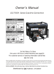
Owner's
GG5500
Using a _er_r
ln_
_oe
NEV_ use |esl_ a _me
er ga,_ge_ EVEN IF do_
un g_d_
Series Gasoline
Generators
CAN _rj_ YOU _ _NLK_
Gen_ator exhaust ¢_ins
UUl_t
Manual
_noxi_
This
Only u_e OUTS_E
far _
_
_n_,
de_
_
MATARA £N _Nt,ffOS,
E! es_pe _ene
_do
_bxi_ us_
r_ Io W_
_ _ono,
v_ nl o|e_r.
NUNCA _llf_ _ _ _r
emir_s en pa_.ee_
tales _o
g_
n[
un
_MENTE
_o
_
|ejos _ vene,ar_s a_.
y
Do Not Return To Store
One year or 60 hours Limited Warranty (see page22)
For customer service or warranty information call toll free
866 797 2738
Read
yourself
could
carefully
and
result
reference.call
before
others
in
attempting
by observing
personal
toll
DISCLAIMER:
injury
free
n umber
to assemble,
all
and/or
install,
operate
information.
property
or maintain
Failure
damage]
866 79 7 2 738 for
All pictures
Distributed
safety
parts
the product
to comply
retain
and
user
described.
the
user,
,s manual
Protect
s man
for
ual
future
service.
may not be identical
by j....
_,US_Fullerton,
the
with
to product
CA 92833
inside
box.
CONTENTS
1 .GENERATOR SAFETY .................................................................
2.COMPONENT IDENTIFICATION ....................................................
3.PRE-OPERATION
CHECK LIST .....................................................
4.STARTING THE ENGINE ..............................................................
5.GENERATOR USE .......................................................................
6.STOPPING THE ENGINE ..............................................................
7.MAINTENANCE
...........................................................................
8.STORAGE ..................................................................................
9.TROU BLES H OOTI NG ..................................................................
10.WIRING DIAGRAM ....................................................................
11.SPECIFICATIONS
.....................................................................
12.WHEELKIT ..............................................................................
13.PARTS LIST AND DIAGRAM .....................................................
13.1 CRANKCASE ASSY, •..............................................................
13.2 CYLINDER HEAD ASSY. ..........................................................
13.3 CAMSHAFT ASSY. •...............................................................
13.4 CRANKSHAFT ASSY. ..............................................................
13.5 CRANKSHAFT ASSY. & PISTON ...............................................
13.6 CENTRIFUGAL TIMING IMPLEMENT ASSY.. ...............................
13.7 INFLAME ASSY,. .....................................................................
13.8 STARTER ASSY. ......................................................................
13.9 ENGINE SPROCKET COVER ...................................................
13.10 CARBURETOR ASSY. ............................................................
13.11 AIR CLEANERASSY.
•............................................................
13.12 CHOKE ROD ASSY. •..............................................................
13.13 GENERATOR .......................................................................
13.14 GAS TANK ASSY. •................................................................
13.15 PANEL ASSY.- ......................................................................
13.16 MUFFLER ASSY. ...................................................................
13.17 FRAME ASSY.. ......................................................................
13.18 MOTOR SHIELD ASSY. ..........................................................
14 PARTS REPLACEMENT LIMITED WARRANTY ..............................
15 PRODUCT REGISTRATION CARD ..............................................
Warranty
anti
Missing
Call
Service
Questions
or Damaged
parts
g66797
273g
-1-
?
2
2
3
4
5
8
8
10
10
11
12
13
13
13
14
15
15
16
16
16
17
.17
17
18
18
19
19
20
20
21
21
22
23
1.GENERATOR
SAFETY
/ii '
DO NOT USE INSIDE HOUSE.
KEEP FLAMMABLE MATERIAL
AT LEAST lm(3FT).AWAY
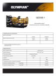
2.COMPONENT
%-
DO NOT USE IN WET
SURROUNDING.
NO SMOKING.
DO NOT CONNECT TO
HOUSEHOLD CIRCUIT.
DO NOT SPILL.
STOP ENGINE.
BEFORE REFUELING
iDENTiFiCATiON
1 FUEL TANK CAP
1
2 FUEL GAUGE
2
3 FUEL TANK
4 HOUR METER
5 DC PROTECTOR
6 GROUND
TERMINAL
7 DC TERMINALS
1
1
8 FORE POLE SOCKET
9 DOUBLE
SOCKET
10 CIRCUIT
BREAKER
11 VOLTMETER
171
15 14 13
0
12 OIL FILLER CAP
13 OIL DRAIN PLUG
14 ENGINE SWITCH
15 HANDRAIL
16 RECOIL STARTER
17 FUEL VALVE
18 AIR CLEANER
19 CHOKE ROD
21
20 SPARK PLUG
21 MUFFLER
Warranty
and Service Questions
Missing or Damaged
parts
Call 866797
2738
-2-
?
20
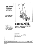
3.PRE-OPERATION
CHECK
1.OIL LEVEL
CAUTION: Be sure to check the generator
Recommended
oil:4=stroke
engine fluid levels with the generator
motor oil service classification
on alevel
surface
SJ,SL, SG or SAE 10W-30 for general
temperature.
1.Remove the oil filler cap/dipstick and
wipe off any oil.
2.Insert the oil filler cap/dipstick into
oil filler neck,but do not screw it in!
Let the filler cap/dipstick sit above
the oil level.
3.Add oil if the oil level is low
before starting.
2.FUELLEVEL
1 Remove the fuel tank cap.
2.Checkthe
fuel level if
the fuel level is low.
3.Add the unleaded gasoline
4. Install the fuel tank cap.
to the shoulder of the
filter screen.
Warranty
and Service Questions
Missing or Damaged
parts
Call 866797
2738
-3-
?
3.AIRCLEANER
1.Unsnaptheair cleanercoversprings,andremovethe air cleanercover
2.Checkthe air cleanerelementtobe sureit isclean andin goodcondition.
3.If it isdirty,removeandclean
the element.
4.STARTING
1.Disconnect
(1)Washin solvent
(2)Squeeze
(3)Soakoil
(4)Squeezedry
THE ENGINE
2.Turn the fuelvalve
any load from the
AC receptacle.
3.Pull the choke rodout
Check the air cleaner
4.Reinstallthe air cleanerelement
andsecurethe coverbysetting
the coverspring.
to
the "ON "position.
to the "CLOSED"
element
position.
tobe sure itis clean.
4.Turn
"ON'position.
Warranty
and Service Questions
Missing or Damaged
parts
Call 866797
2738
=4=
the engine
?
switchto
the
J
5.Pull the starter
grip lightly
until resistance
is felt
then pull briskly.
Warning:Do
not allow the starter grip to snap
back against the engine.
Return it gently.
5.GENERATOR
, To keep the generator
6.Push the choke rod to the "OPEN"
position
as the engine warms up.
USE
always
in top mechanical
and electrical
1 .To prevent electrical shock from faulty appliances,
the generator
condition,
observe the following:
_ ....... _:_
should be grounded.
Connect a copper wire to the generator and the other end of wit
to a metal stake driven into the ground.
2.Combined
load of the connected
Electric apparatus,
particularly
apparatus must not exceed the rated capacityof
motor-driven
equipment,
following table is provided for your reference
STARTING RATED
E-o_
will draw a higher currentwhen
EXAMPLE
TYPICAL APPARATUS
incandescent
lamp
APPARATUS
incandescent
STARTING
RATED
100VA
100VA
(w)
(w)
80VA
60VA
(w)
(w)
lamp
Xl
Ct,_
eU r5
O ©
@TV
jc::E
100W
E
t"5
o
X2
X1.5
o
40W
Fluorescent
14-
lamp
E
lamp
X3~5
efrigerator
450~750VA
X2
e>
O
Fluorescent
Refrigerator
"-_
o-
the generator
starting. The
when connecting such apparatus to your generator.
WATTAGE
TYPE
Xl
_,{_;
_
(w)
_'_150W
Electric fan
Warranty
and Service Questions
Missing or Damaged
parts
Call 866797
2738
=5=
?
300VA
(w)
3.When
twoor
more pieces of apparatus
with the one drawing
higher currentwhen
are connected
toyour
generator,
turn them on beginning
starting.
ACAPPLICATION
1.Start the engine
2.Make
sure that the needle on the voltmeter
indicates
the voltage.
o
3.PlUgNote:
in the appliance
a: Over current will automatically
turned off, the generatorshall
minutes
thatis'i_%'_
turn off theAC
be restarted
breaker. When
with load reduced
_.
a few
thereafter.
B: Generally
5-10% variance
of voltage output
is allowed.
Warranty
and Service Questions
Missing or Damaged
parts
Call 866797
2738
-6-
?
DC APPLICATION
The DCterminats
1.Connect
2.Start
may be used for charging
the charging
12V automotive-type
cables to the battery
batteries
only
terminal.
the engine and charge the battery
NOTE:
An overloaded
DC circuitwill
trip the DCcircuit
breaker
(push button comes out) If this happens.check
circuit
or counter
connection
the short
and wait a few minutes
before pushing the circuit protector.
3.Stop the engine,then
charging
disconnectthe
cables in the reverse orderof
connection.
(1)
ON (2)
7:B/2_ p""
OFF
6.STOPPING
THE ENGINE
1.Turn off all electrical
appliances.
2.Turn theengine switch
to the "OFF " position.
o
3.Disconnect
appliance.
the electrical
4.Turn thefuel valve to the
"OFF"
position.
NOTE: To stop the engine in an emergency,turn
Warranty
and
Missing
the engine switch OFF.
Service
Questions
o:r Damaged
Call 866797
-7-
paris
2738
'?
7.MAINTENANCE
(1):These
(2):Every
itemsshoule
3 years
be serviced
(_
Check
bya dealer.
Change
Clean
(_)
Check-Readjust
SEE page
First orm°nth
Every
3ormonths
Every 6rn_Ont hs
EVeroYrYear
Engine
oil
P.3
P.9
Air cleaner
0
@
I9
Fuel strainer
Battery
fluid level
@
P.9
@
P.9
(_
Spark plug
ValveClearance
Combustion
Chamber
Fuel line
___
@(1)
_
@(1)
I_
_
(_)
1.OIL CHANGE
4.Install the drain plug and tighten it securely.
1.Remove the oil filler cap.
5.Refill with the motor oil(see 3 page)and check the oil level
2.Remove the drain plug and drain the oil.
ENGINE OIL CAPACITY:37.2oz(1.1
3.Dispose of oil property.
&Install the oil filler cap.
Recommended
oil: 4-stroke motor oil service
temperature.
classification
SJ,SL,SG
Warranty
and Service Questions
Missing or Damaged
parts
Call 866797
2738
=8=
?
Liter)
or SAE 10W-30 for general
2.AIR CLEANER(See4
3.SPARK
page)
PLUG
TYPE:FTRTC(NGK=BPR6ES)
%
5.Reinstall
1.Remove
the spark plug cap.
2.Remove
(0.028~0.031in)
the spark plug.
J
the spark
plug and plug cap.
4.Measure
the gap.
3.Clean
the deposit.
4.FUEL STRAINER
1.Turn thefuel
valve
2.Clean
the sediment
to the OFF position
cup and fuel filter
and remove the se
screen.
diment cup and
filter screen.
3.Install
thefuel
filter screen and sediment
cup.
8.STORAGE
1.Close the fuel valve, drain
the fuel from the fuel tank.
2.Drain the fuel from the carburetor.
3.Remove the oil filler cap
and drain plug to drain
the oil.
-.q
4.Tighten the oil drain plug
and fill the engine with
new oil to the filler neck.
5.Pull the starter grip carefully
until resistance is felt.
Warranty
and Service Questions
Missing or Damaged
parts
Call 866797
2738
=9=
6. Store the generator
in a clean area.
?
9.TROUBLE
SHOOTING
ENGINE DOES NOT START:
1.Turn on the engine switch.
2.Check fuel.
3.Check oil.
p,-
5.Check spark.
4.Remove spark plug.
NO ELECTRICITY:
Check AC circuit
Warranty
and Service Questions
Missing or Damaged
parts
Call 866797
2738
-10-
?
breaker
In case long term storage
breaker
generator
and prod the ARM to increase
has no output
the throttle
when started,please
until thevolt-meter
indicates
RM
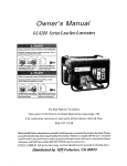
1 0.WIRING
B,,,L._
DIAGRAM
l
FIELD WINDING
MAIN
WENDING
ENGINE
SWITCH
H
Warranty
and Service Questions
Missing or Damaged
parts
Call 866797
2738
-11
-
?
turn off the circuit
voltage
1 1 .SPECIFICATIONS
Package(LxWxH)(in)
32.1x21.26x22.05(815×540x560mm)
Net weight(Ibs)
178.6(81kg)
Model
GG5500
Type
Rated
Rated
Single
phase,Brushless
voltage(V)
120/240
frequency(Hz)
Rated
current(A)
Rated
power(kW)
60
41.67/20.83
5.0
Max.power(kW)
Power
5.5
factor(cos(
4)))
1.0
DC rated
voltage(V)
12
DC rated
current(A)
10
Safety
device
N.F.B
Engine
ZJ182FPH
Type
Air-cppled
Bore x stroke
Displacement
Output
(in)
single
3.23x2.52(82mm×64mm)
(cc)
338
MAX.(Hp/rpm)
Start
Operation
Ignition
cylinder.4-stroke
11/3600
mode
Recoil
time(hr)
start
9
system
TCI
Fuel type
Unleaded
Oil type
SAE 10W-30/SAE
Note: specifications
gasoline
10W-40
subject to change without prior notice.
Warranty
anti
Missing
Call
Service
Questions
or Damaged
parts
866797
2738
-12-
?
engine
12.WHEEL
KIT
1 .Install the twowheeis
generator
2.Install
on the
using two bolts.
the standson
the underframe.
/
1 3.PARTS
13.1
NO.
LIST AND DIAGRAM
WHEELS
CRANKCASEASSY
PARTS
NO.
DESCRIPTION
QTY
1
QJ182QDP.01-11
Buse, locating
2
2
157.5-10
SPACER, drain
2
3
157.5-9
BOLT, drain
2
4
QJ150FMG.5-8
DOWEL PIN
2
5
GB5787-86
BOLT M6x 12
4
6
QJ182QDP.01.04
Sensor Assy, Fuel level
1
7
157-1-6-13
NUT
1
8
QJ182QDP.01-01
COVER, CRANKCASE
1
9
QJ168QDJ.01-05
SEAL WASHER
2
10
QJ168QDJ.01-03
PLUG, ADD OIL
1
11
GB5787-86
BOLT M8x40
7
12
QJ182QDP.01.01
OIL SEAL 52X 34X8
2
13
QJ168QDJ.01-04
OIL LEVEL STICK
1
14
QJ182QDR01-03
SPACER, CRANKCASE
1
15
GB/T276-94
Bearing6202
2
16
GB/T276-94
Bearing6207 35 × 72 × 17
1
17
QJ182QDR01-10
Pin
1
18
QJ182QDR01-05
ELECTRONIC
19
QJ182QDR01-09
CLIP, Cord
20
QJ182QDR01-08
SEAL GASKET, rubber
1
21
GB5787-86
BOLT M6× 25
2
22
QJ182QDR01.03
OIL SEAL
1
23
QJ182QDR01.02
CRANKCASE ASSY
1
15x35x11
SWITCH
22
12
18
"7
16
2
1
1
Warranty
and Service Questions
Missing or Damaged
parts
Call 866797
2738
=13=
?
8
6
10 5
9
13.2 CYLINDER
NO.
PARTS
HEAD ASSY
NO.
DESCRIPTION
QTY
1
QJ182QDR02.01
Cylinder
HeadAssy
1
2
QJ182QDR02-01
Bolt, Cylinder
3
QJ182QDR02.02
4
QJ182QDR02-03
5
QJ182QDR02-04
Clamp
1
6
QJ182QDR02-02
Bolt
1
7
QJ182QDR02.03
Spacer Assy
1
8
QJ182QDR02-05
Bolt, Intake Pipe
2
9
QJ182QDR02-06
Cowling
1
10
GB5787-88
Bolt M6× 12
1
11
QJ182QDR02-07
12
QJ182QDR02.04
13
QJ182QDR02.02-02
14
QJ182QDR02.01-05
15
QJ182QDR02.01-03
Canal, Exhaust
16
QJ182QDR02.01-04
Ring,
17
QJ182QDR02.01-04
Ring, Intake Valve
1
18
GB/T6177-2000
Nut M6
2
Head
Cover Assy
Spacer,
6
4
5
1
Seat
1
i8
i8
Spacer,
Intake
Pipe
I3
i0
14
1
15
Spark
Ptug(NGK-BPR6ES)
1
Washer
Canal,
1
Intake Valve
12
1
Valve
1
I
Exhaust
Valve
1
Warranty
and Service Questions
Missing or Damaged
parts
Call 866797
2738
-14-
17
i¸6
?
13.3
NO.
CAMSHAFT
PARTS
ASSY
NO.
DESCRIPTION
1
QJ182QDR03-12
Exhaust valve
1
2
QJ182QDR03-11
Lower retainer
1
3
QJ182QDP.03-05
Valve spring
2
4
QJ182QDR03-08
Exhaust vNve spring retainer
1
5
QJ182QDR03-09
Valve rotator
1
6
QJ182QDR03-04
Pivot bolt
2
7
QJ182QDR03-06
Valve rocker arm
2
8
QJ182QDR03-07
Rocker arm pivot
2
9
QJ182QDR03-11
10
QJ182QDR03-10
Intake valve spring retainer
1
11
QJ182QDR03.02
Push rod
2
12
QJ182QDR03-03
Push rod guide plate
1
13
QJ182QDR03-13
Intake valve
1
14
QJ182QDR03-01
Valve lifter
2
15
QJ182QDR03.01-06
Spring
1
16
QJ182QDR03.01-02
Pin I
1
17
QJ182QDP.03.01.01-01
Pivot adjusting
9
QTY
nut
8
/
6
5
11
2
12
2
1
24
1
Fty clump
]_
1
18
QJ182QDP.03.01.01-02
Fly clump ][I
1
19
QJ182QDP.03.01.01-03
Pin IV
2
23
/
\
\
I
\
\
21 \
20
QJ182QDR03.01-03
21
QJ182QDR03.01-01
22
QJ182QDR03.01-04
23
QJ182QDR03.01-05
24
QJ182QDR03.01
13.4
NO.
CRANKSHAFT
PARTS
Pin II
1
Camshaft
Decompress
1
clump
1
Pin Ill
Camshaft
t
1
comp.
1
ASSY
NO.
DESCRIPTION
1
QJ182QDR04-01
BALANCE
2
QJ182QDR04-02
NUT
3
QJ182QDR04-03
WOODRUFF
4
QJ182QDR04-04
QTY
SHAFT
1
1
KEY
1
CRANKSHAFT(I-type)
4
1
5
QJ182QDR04-05
CRANKSHAFT
GEAR
I
1
6
QJ182QDR04-06
CRANKSHAFT
GEAR I!
1
7
GB/T276-94
Bearing6207
5
7
1
Warranty
and Service Questions
Missing or Damaged
parts
Call 866797
2738
-15-
?
13.5 CRANKSHAFTASSY&
NO.
PARTS
PISTON
NO.
DESCRIPTION
QTY
1
QJ182QDR05-01
PISTON
1
2
QJ182QDR05-02
RING 1ST
1
3
QJ182QDR05-03
RING 2ND
1
4
QJ182QDR05.01
RING SET OIL
1
5
QJ182QDR05-04
PIN, PISTON
1
6
QJ182QDR05-05
CIRCLIP
2
7
QJ182QDR05.02
CONNECTINGROD ASSY
1
8
QJ182QDR05-02-01
9
QJ182QDR05-02-02
CONNECTIONGROD CAP
1
10
QJ182QDR05-02-03
CONNECTINGROD BOLT
2
13.6
NO.
CENTRIFUGAL
PARTS
CONNECTING
TIMING
NO.
ROD
1
IMPLEMENTASSY
DESCRIPTION
QTY
1
QJ182QDR06-09
Pull Pole,
steel wire
1
2
QJ182QDP.06-10
Putt spring,ittte
1
3
QJ182QDR06-01
Putt Ploe, Timing
implement
1
4
QJ182QDP.06-08
Pull spring, big
1
5
GB6177-2000
Nut M6
1
6
QJ182QDR06-05
Washer
7
QJ 182QDR06-04
Fork
1
8
QJ182QDR06-01-03
Governor weight
3
9
QJ 182QDR06-01-02
Governor weight pin
3
10
QJ166QDK.06-07
Washer [It
1
11
QJ182QDR06.01-01
Centrifugal
Timing Implement
1
12
QJ166QDK.01-02
Clip
1
13
QJ182QDR06-07
Washer H
1
14
QJ182QDR06-06
Handspike Cover
1
15
QJ182QDR06-02
Clip
1
16
QJ182QDR06-03
Bolt, Square Toes
1
]
1
_6
_7
8
9 ¸
13.7
NO.
INFLAME
PART
13 12
/
11
I
ASSY
NO.
DESCRIPTION
QTY
1
QJ182QDP.07.02
ROTOR ASSY
1
2
QJ182QDP.07.01
high vottage wrap
1
Warranty
and Service Questions
Missing or Damaged
parts
Call 866797
2738
-16-
?
Uio
F-°
13.8
NO.
STARTER
ASSY
PARTS
NO.
DESCRIPTION
QTY
1
QJ182QDP.08.01-10
Handle
1
2
QJ182QDP.08.01-11
Putt Rope
1
/
/
/
3
QJ182QDP.08.01-09
Clockwork
Spring
1
4
QJ182QDP.08.01-03
Rotary Table
1
5
QJ182QDP.08.01-05
Spring, Return
2
6
QJ182QDP.08.01-07
Screw
1
7
GB5789-86
Bolt M6x12
5
8
QJ182QDP.08-01
\
\
\
5
Starter Canister
7
1
\
9
QJ182QDP.08-02
Fan Wheel
\
7
1
14
7\\\\ \
\
13
\
\
\
\
\
10
QJ182QDP.08.01-01
CowlingAssy, cyainder
1
11
QJ182QDP.08.01-08
Guide Pan
1
\
12
x
\
12
QJ182QDP.08.01-04
Clump
2
13
QJ182QDP.08.01-06
Press Reed
1
14
QJ182QDP.08.01-02
Washer
1
15
QJ182QDP.08.01.01
Starter Cover Assy
1
16
G B5789-86
Bolt
3
7
\
k
11
\
\
\
\
10
\
\
17
QJ168FJH-3.08.01
Switch
1
18
QJ182QDP.08.01
Starter Assy
1
13.9
NO.
ENGINE
SPROCKET
PARTS
\//
COVER
NO.
DESCRIPTION
QTY
1
QJ182QDP.09
Speed djustment
base assembly
1
2
QJ168QDJ.05.01-02
Spring
1
ScrewM5x35
1
t
3
13.10
NO.
G B818-2000
CARBURETOR
PARTS
NO.
_
\
I
ASSY
DESCRIPTION
Carburator
QTY
1
QJ182QDP.10.01
2
QJ182QDP.10-01
3
QJ153FM-0000041
Clip
1
4
QJ182QDP.10-02
Hose¢4.5x ¢ 8.5x210
1
5
QJ182QDP.10-03
Hose¢9x_
1
Carburetor
Assy
1
packing
1
12x150
Warranty
and Service Questions
Missing or Damaged
parts
Call 866797
2738
-17-
?
2
3
13.11 CARBURETOR
NO.
1
PARTS
ASSY
NO.
DESCRIPTION
QJ 182QDR 11
QTY
Air Cleaner Assy
1
2
QJ182QDR11-6
Clip, Fixup I
2
3
QJ182QDR11-7
Clip, Fixup II
2
4
QJ182QDP./11-8
Air Cleaner Cover
1
5
GB6177-2000
NUT M5
6
6
QJ182QDR11-9
Core, Filtrate
1
7
QJ182QDR11-3
Hole Board
1
8
QJ182QDP.11-4
Seal Gasket,
1
9
QJ182QDR11-5
Below Shell, Air Cleaner
1
10
QJ182QDR11-2
Air Cteaner
1
11
GB6177-2000
NUT M6
1
13.12
NO.
CARBURETOR
PARTS
\
\
ASSY
NO.
DESCRIPTION
QTY
1
QJ182QDR02.02-03
Breath Tube
1
2
QJ182QDR02.02-04
Rubber galosh
1
3
QJ182QDR10.02
4
QJ182QDR10.02-03
5
QJ182QDR10.02.01-01
6
QJ182QDR10.02.01-02
7
QJ182QDR10.02.01.01
Choke vavte variable
pump comp.
1
Clip
1
Clip
4
Hose ¢4x¢8x135
Valve
2
/
t4
1
8
QJ182QDR02-08
Bakelite Washer
1
9
QJ182QDR10.02-04
Rubber galosh I
1
10
QJ182QDP.10.02.01
Valve Assy
1
11
QJ182QDP.10.02-01
Choke vavte Putt pole
1
12
QJ182QDR 10.02-02
Rubber gatosh ][
1
13
QJ182QDR 10.02.02
Breath body Assy
1
14
QJ182QDP.11-1
Air cleaner Packing
2
15
QJ182FPH-2.07-01
Putt pole
1
I
/
/
Warranty
and Service Questions
Missing or Damaged
parts
Call 866797
2738
-18-
?
13.13
GENERATOR
NO.
CODE
DESCRIPTION
QTY
1
GB/T5787-86
Bolt IV15"12
2
2
QJ6500.03-04
Right Cover
1
3
GB/T5780-86
Bott M5"20
2
4
GB/T5789-86
Bott M5"12
4
5
QJ6500.03-03
Connector
1
6
GB/T5789-86
Bolt M5"12
1
7
QJ6500.03.03
Rectifier
1
8
GB/T5780-86
Bolt M10"250"1.25
1
9
QJ6000.03-02
Motor Shell
1
10
QJ6500.03.01
Rotor Assy
1
11
QJ6500.03-06
Motor cover
1
12
QJ6000.03.03.01
BEARING, needle
1
13
QJ6500.03.02-01
RotorAxis
1
14
QJ6000.03.03-07
Rotor Wire Support
1
15
QJ6000.03.03-09
Rotor Loop Platen
2
16
GB/T5787-86
Bolt M6"16
2
17
GB/T6177-86
Nut M6
2
18
QJ6000.03.03-08
Alnico
1
19
QJ6000.03.03-02
Impeller Retainer
1
20
QJ6000.03.03-01
Impeller
1
21
GB/T95-85
Washer
3
22
GB/T93-87
Spring Washer
3
23
GB/T818-85
Bolt M5"12
3
17
_6
13.14GASTANKASSEMBLY
NO.
CODE
DESCRIPTION
1
QJ6500.01.01
Fuel Tank Comp
1
2
QJ950.13-02
Filtering Net
1
3
QJ3000.01.04
4
GB/T819-85
Screw M5"10
2
5
QJ3000.01.03
Sender Unit
1
6
GB/T5787-86
Bolt M6"20
4
7
GB/T95-86
Washer
4
8
QJ2600.01-02
Fuet Tank Rubber Hose
4
9
QJ2600.01-01
Fuel Tank Rubber
4
10
QJ6500.01.02
Fuel Valve
1
Sump Cover
Subassembly
QTY
I
4
Warranty
and Service Questions
Missing or Damaged parts
(;all 866 797 2738
-19-
?
13.15
N O.
PANEL ASSY
CODE
DESCRI PTI ON
QTY.
Engine Switch
1
1
QJ6500.02.02
2
QJ6500D.01.01
Panel
1
3
QJ6500D.01-01
Bottom Shell
1
4
QJ6500.02.07
Carburetor Controller
1
5
QJ6500.02.03
Circuit Breaker
2
6
QJ3200.01.02
3-Pole Socket for USA
2
7
GB/T6177-86
Nut M4
7
8
QJ6500D.01.03
4-Pole Socket
1
9
QJ6500.02.04
DC Protector
1
10
QJ6500.02.06
Capacitance
1
11
GB/T5787-86
Bolt M6"16
4
12
GB/T6170-86
Nut M6
2
13
GB/T923-88
Nut M6
1
14
QJ6500.02.05
DC Terminal
2
15
GB/T818-85
Screw M4"12
7
16
GB/T818-85
Screw
4
17
QJ2600.02.05A
Voltmeter
1
18
QJ6500D.01.04
Hour Meter
1
,5
7
8
13.16
N O.
M3"4
MUFFLERASSY
CODE
DESCRIPTION
QTY.
1
QJ6500.07.01
Muffler
1
2
QJ6800.05-01
Muffler Cover
1
Warranty
and Service Questions
Missing or Damaged
parts
Call 866797
2738
-20-
?
13.17
FRAMEASSY
NO.
CODE
1
QJ6500D.04-06
Wheel Axis Bolt
2
2
QJ6500D.04.02
Wheel 4.10/3.5
2
3
QJ6500D.04.01A
Frame Jointing Assy
1
4
GB/T6177.1-2000
Nut M10"1.25
4
5
QJ6000.08.02
Shockproof Big Mounting Feet
2
6
QJ6000.08.03
Shockproof Small Mounting Feet
2
7
GB/T6177.1-2000
Nut M6
2
8
GB/T5789-86
Bolt M6"40
2
9
QJ6500D.04-01, _
Handrail
2
10
QJ6500.04-02
Handrail Jacket
2
11
GB/T6177-2000
Nut M8
10
12
GB/T5780-2000
Bolt M8"16
4
13
QJ6500D.04-03, _
Crutch
2
14
QJ6800.06-02
Crutch Jacket
2
13.18
NO.
1
MOTOR
DESCRIPTION
QTY.
14
SHIELDASSY
CODE
QJ6500.03-05
DESCRIPTION
QTY.
Motor shield
1
Warranty
and Service Questions
Missing or Damaged
parts
Call 866797
2738
-21
-
?
1 4. Parts Replacement
IMS-UST
warrants
to the original
purchaser
one (1) year or 60 hours from the original
hours,
whichever
warranty
period
warranties
comes
first.
that the mechanical
date of purchase
All costs
associated
are the sole responsibility
will be processed
without
(whichever
proof
components
is first).
with the transportation,
of the purchaser.
valid
and electrical
Limited Warranty
For commercial
diagnosis
This warranty
will be free of defects
and industrial
and replacement
only applies
in material
use, the warranty
of parts determined
to the original
and workmanship
for a period
is applicable
for 90 days or 60
to be not operable
purchaser
and is not transferable.
Technical
Service
of
during
this
No claims
for
of purchase.
For Help with Your Warranty
0[[,?0not
retUUll'_Hthe
u_t
to the
p_ace
of
Contact
IMS-USTs
problems
with this product
corrected
as a result
evaluate
part of the unit.
IMS-UST
AND
ALL TRANSPORTATION
PREPAY
NUMBER
consult,
INCLUDED
will provide
ON THE
return authorization,
you with a case number
CHARGES.
SHIPPING
pre-paid
NO UNITS
LABEL.
freight
return)
for warranty
service.
SENT
No exceptions
TO IMS-UST
to this warranty
will result in no parts replaced
What is not covered
•
Normal
•
Problems
Wear
caused
by using dirty or otherwise
•
Problems
caused
by not properly
Maintaining
•
oil volume
need periodic
the equipment
•
•
adjustments,
•
Failures
•
Problems
•
This warranty
and service
crankcase
is critical
to perforn_
engine.
This warranty
procedure
are allowed.
will
or replacement
of the defective
OF THE PURCHASER
TO ARRANGE
AT IMS-UST
Failure
at its option
to follow
WITHOUT
A VALID
the steps outlined
CASE
(phone
the warranty
by this Warranty
oil type and fluid level.
to the safe and effective
well. This warranty
This unit is equipped
with a low oil auto shutoff
sensor.
use of the motor.
does not cover
repair
when
normal
use has exhausted
the life of a part or
Operating
installed
cleaning,
this unit in environments
is deemed
improperly
to have been misused,
or connected
spark plugs and obstruction
Warranty
where
the air temperature
and relative
humidity
are extreme
will
does not cover those situations.
incorrectly
neglected,
to any electrical
due to contaminant
and Consequential
Damage
buildup
involved
component.
are not covered
in an accident,
Normal
abused,
maintenance
loaded
beyond
such as air filters,
by this warranty.
- issuesspecificallynotcoveredunderthewarranty.
defects.
due to acts of God and other forces
IMS-UST
the correct
maintaining
limits, modified,
of Implied
Cosmetic
fuel.
in the crankcase
by an air cooled
fuel system
•
contaminated
will not apply to parts if this generator
the generator's
•
parts
parts to malfunction.
This warranty
Limits
BE RECEIVED
a repair
IMS-UST
your
is not
as a whole.
This unit is powered
cause
and will authorize
will troubleshoot
If the problem
or email contact,
RESPONSIBILITY
WILL
under
of the phone
or e-mail.
and Tear
proper
Generators
the issue
IT IS THE
and IMS-UST
via phone
caused
of natural
by parts that are not original
will not cover any damages
disclaims
any obligation
events
beyond
the manufacturer*s
control.
OEM parts.
that occur from the user's
failure
to follow
to cover any loss of time, use of this product,
the instructions
freight,
and warnings
or any incidental
provided
or consequential
in the manual.
claim by anyone
from
using this generator
•
Parts provided
period
THERE
of the warranty
IS NO OTHER
RETAILER
LIABILITY
This warranty
listed within
IN WHICH
FOR
as a replacement
from the original
EXPRESS
CASE
INCIDENTAL
gives you certain
will be subject
ANY
purchase
WARRANTY.
IMPLIED
ALL
which
of the original
unit. The length
of the warranty
will never exceed
the total time
date.
IMPLIED
WARRANTIES
OR CONSEQUENTIAL
legal rights
to the warranty
DAMAGES
may change
WARRANTIES
ARE THE
ARE EXCLUDED
RESPONSIBILITY
ARE EXCLUDED
from state to state. Your
OF THE
TO THE
UNLESS
PROVIDED
RETAILERS
EXTENT
EXCLUSION
state may also have other rights
this warranty
Warranty
and Service Questions
Missing or Damaged parts
Call 866 797 2738
-18-
WHO
?
BY AN INDEPENDENT
EXTENDED
IS PERMITTED
you may be entitled
THEM.
BY LAW.
to that are not
PRODUCT
REGISTRATION
CARD
For more efficient customer service, please fill out the information below and mail to International
ing Service,Inc
Model No.
Engine Serial No.
Purchased from: [ ]Retail location
Merchandis-
Purchase Date
[ ]Other
[ ] Private Consumer
Name:
Location Address:
Purchase Price:
Telephone w/area code:
Purchased:E ] NEW or I ]USED
Consumer
Information:
Name
Telephone w/area code:
Suite or Apt No
Street Address'
State
City:
Zip Code
Province or Country
[ ]Business or [ ]Residence
Are you a:
Product
usage Information:
How often will you use this product?[
]Everyday
[ ]Periodically
[ ]Emergency
use only
[ ]Other
What type of application
wilt you use this product
in?
[ ]Heavy Commercial
[ ]Moderate Commercial
[ ]Light Commercial
[ ] Tradeshows
[ ]Heavy Residential
[ ]Moderate Residential
[ ]Light Residential
[ ]Camping,backpacking
[ ]Other
Mail this page to Internation Mer Service,Inc,
1928 West Malvern Avenue
Fullerton,CA92833
Warranty
and Service Questions
Missing or Damaged parts
Call 866 797 2738
-19-
?