1
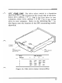
~~VERE Everdisk
rM
internal/external
hard disk subsystem
(XT compatible)
OWNER'S MANUAL AND REFERENCE GUIDE
(VERSION 2.0)
EVER for EXcellence
MAN-00007-20 Everdisk™ internal/external
hard disk subsystem
(XT compatible)
OWNER'S MANUAL AND REFERENCE GUIDE
EV-390
EV-391
EV-392
(VERSION 2.0)
EVEREX SYSTEMS, INC. 48431 MILMONT DRIVE FREMONT, CA 94538 Notice Everex Systems, Inc. reserves the right to make
improvements in the product described in this manual at
any time and without notice.
DISCLAIMER: While we do our best to avoid such a situation,
Everex Systems will not be responsible for loss of data resulting
from the use of this product.
This manual is copyrighted. All rights are reserved. This
manual may not, in whole or in part, be copied, photocopied,
reproduced, translated, or reduced to any electronic medium
or machine-readable form without prior consent, in writing,
from Everex Systems, Inc.
(C) Copyright August, 1987
Everex Systems, Inc.
ii
r-..
Everex, EVER for EXcellence, and
trademarks of Everex Systems, Inc.
EVERDISK
are
The IBM PC, XT, AT, Portable and PC-DOS are trademarks
of International Business Machines Corporation.
MS-DOS is a trademark of Microsoft Corporation.
Compaq and Deskpro are trademarks of Compaq Computer
Corporation.
Micropolis, 1333A and 1335 are trademarks of Micropolis
Corporation.
,-.,
Miniscribe 3650 is a trademark of Miniscribe Corporation.
NEC 5146 is a trademark of NEC Home Electronics (USA),
Incorporated.
Seagate, ST213, ST225, ST238, ST251, ST4026, ST4038, ST4051,
and ST4096 are trademarks of Seagate Technology,
Incorporated.
iii
Warning Class B: Computing Device
WARNING: This equipment generates and uses radio frequency energy and
if not installed and used in strict accordance with the manufacturer's
instructions, it may cause interference to radio and television reception. The
product has heen certified and found to comply with the limits for a Class B
computing device in accordance with the specifications in Su bpart J of Part
15 of FCC Rules, which are designed to provide reasonable protection against
such interference in a residential installation.
However, there is no
guarantee that interference will not occur in a particular installation. If this
equipment does cause interference to radio or television reception, which can
be determined by turning the equipment off and on, the user is encouraged
to try to correct the interference by one or more of the following measures:
1. 2. 3. 4. 5. Ensure that card mounting screws, attachment connector screws, and
ground wircs are tightly secured.
Reorient the computer with respect to the receiver.
Move the computer away from the receiver.
Plug the computer into a different outlet so that computer and receiver
are on different branch circuits.
Reorient the receiving antenna.
This product requires the use of shielded interconnect cables and connectors
for proper installation and connection to peripheral devices and to insure
compliance with FCC Class B limits for radio frequency emissions. Shielded
cables are available from authorized dealers.
The manufacturer is not
responsible for any radio or television interference caused by using other
than the recommended cables or by unauthorized modifications to this
equipment.
necessary, the user should consult the dealer or an experienced
radioltelevision technician for additional suggestions. The user may find the
following booklet prepared hy the Federal Communications Commission
helpful: "How to Identify and Resolve Radio TV Interference Problems."
This booklet is available from the U.s. Government Printing Office,
Washington, D.C. 20402, Stock No. 004-000-00345-4 (FCC, Part 15.838 h).
If
ill
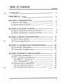
Table oj Contents 1"""'\
CHECKLIST .•..._ ......................................._ .......................__..............._
1
USER PRECAUTIONS...............................................................................
4
SECTION 1: INTRODUCTION ..............................................................
1.1 Before You Begin ...............................................................................................
1.2 System Requirements.....................................................................................
5
5
6
SECTION 2: GETTING STARTED.....................................................
2.1 Quick Installation (Internal Drive).........._._........................
2.2 Quick Installation (External Drive)............_........................
8
8
9
SECTION 3: DRIVE CONFIGURATION.........................................
3.1 Drive Select Switch ..................................................................................._
3.2 Terminating Resistor............................_ ................................................_
10 10 16 SECTION 4: CONTROLLER CONFIGURATION ......................
4.1 Controller Description ...............__....._ ..................._.............................
4.2 Controller Configuration...._....................................................................
19 20 21 SECTION 5: PHYSICAL INSTALLATION ............__............._....
5.1 Controller Installation..................................................................................
5.2 Internal Drive Installation.....................................................................
5.2.1 One Internal Drive..........._.......................................................,,_
5.2.2 Two Internal Drives...........................................................................
5.3 External Drive Installation....................................................................
5.3.1 One External Drive.............................................._..........................
5.3.2 Two External Drives.........................................................................
27 27 30 30 34 37 37 40 v
SECTION 6: FORMATTING THE HARD DISK........................
6.1 For Older IBM PC Models ............................._......................................
6.2 Physical Formatting.................................._................._............._._..........
6.3 Disk Partitioning........................................................................_......................
6.3.1 Creating Primary DOS Partition........_........._.................
6.3.2 Creating Extended DOS Partition........................._........
6.3.3 Creating Super DOS Partition ............._...............................
6.3.4 Deleting Partitions...............................................................................
6.4 Logical Formatting......................................................................._.................
6.5 Utili ties ...................................................................................._.....................................
6.5.1 The Diagnostics Menu .............._ ................................_ .........._
6.5.2 SHIPDISK.EXE.............................................................._......................
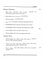
41 42 43 44 45 46 48 50 50 53 53 57 APPENDIX 1: REMOVING SYSTEM COVER ..m.......................
58 APPENDIX 2: INSTALLING ONE EXTERNAL AND ONE INTERNAL DRIVE.............................................................
59 APPENDIX 3: EV-390 CONTROLLER INSTALLATION......
61 APPENDIX 4: CONTROLLER SPECIFICATIONS....................
63 APPENDIX 5: HARD DISK SPECIFICATIONS...•.........._........
65 APPENDIX 6: QUESTIONS AND ANSWERS..............................
68 vi
Check List Your EVERDISK hard disk subsystem should contain the
following items:
Internal Subsystel7'
Hard disk controller board in an anti-static bag
Hard disk drive in an anti-static bag
34-pin ribbon cable
20-pin ribbon cable
Half-height bezel (full-height bezel optional)
Metal mounting brackets
Set of screws
EVERDISK utility diskette (Version 3.0 or later)
EVERDISK Owner's Manual and Reference Guide
Owner Registration and Warranty Card
Foam padding and other packaging materials
1
External Subsystem
Hard disk controller with external
mounting bracket in an anti-static bag
connector
on
Hard disk drive in an external subchassis
37-pin shielded connecting cable
AC power cord (power external subchassis ONLY)
EVERDISK utility diskette (Version 3.0 or later)
EVER DISK Owner's Manual and Reference Guide
Owner Registration and Warranty Card
Foam padding and other packaging materials
Optional Items
34-pin floppy disk ribbon cable with three connectors
(for EV-390 controller ONLY)
34-pin hard disk daisy-chain ribbon cable with three
connectors (for two-drive installations)
Extra 20-pin hard disk ribbon cable (for two-drive
installa tions)
2
If any of the items previously listed are missing or are
damaged, please consult your Everex dealer immediately.
NOTE: Please save all Everex packaging materials that came
with your EVER DISK subsystem; if you ever need to return
your EVER DISK subsystem to Everex Systems for any reason
without proper packaging, your warranty may be affected. As
with any major purchase, please save your sales invoice.
Also, it is very important you read the enclosed warranty
information; the warranty will not take effect until the
warranty card is filled out and returned to Everex Systems.
3
User Precautions To avoid possible hazardous situations and to prevent
damaging your EVERDISK subsystem, please read the
following precautions carefully.
1. Turn OFF your system and disconnect the power cable
before you begin the installation. Make sure NO power
goes to your system!
2. Clear an area around your computer to make working
on your computer easier.
3. The hard disk drive and drive controller are easily
damaged by static electricity; to avoid such damage,
touch the system chassis before handling the drive and
controller, and try not to touch the circuitry on the
drive and controller. Also, limit your movements as
much as possible as you work on your system.
4. The hard disk drive contains fragile parts that are
easily damaged; please handle the drive as gently as
possible.
5. Do not remove any stickers attached to the metal side
of the drive, as this will void the warranty.
6. Do not open the cover of the external drive subchassis;
this will void the warranty, and some internal parts may
produce electrical shock.
4
,-..,
Section 1: Introduction .---.,
1.1 Before You Begin
Before installing your EVERDISK hard disk subsystem,
please read through this manual carefully. This manual
gives you all the information needed to install the
EVERDISK hard disk subsystem in your computer. If you
have any questions not answered by this manual, please see
your local Everex dealer.
REMEMBER: "If all else fails, read the instructions."
Introducing the EVERDISK Subsystem
The EVERDISK hard disk subsystem offers superior
performance, reliability, and rugged construction in hard
disk technology. The EVERDISK subsystem:
Comes complete with controller, drive, and software for
easy installation.
Provides complete compatibility with Version 2.1 or
later of PC-DOS or MS-DOS.
Allows you to boot directly off the hard disk.
Allows you to connect two hard disk drives of different
capacities to the controller board.
5
1.2 System Requirements
IBM PC, XT or compatible
Minimum 128KB of RAM memory
DOS 2.1 or later DOS version
Higher-capacity power supply (only for PC and PC
compatibles with a system power supply of less than 135
watts output).
Please refer to the appropriate section below for special
requirements if you have the following computers:
IBM PC Portable
IBM Portable front bezel for hard disk (optional)
Special short mounting screw (DO NOT use mounting
screws from your floppy disk drive)
Compaq Portable
Compaq DOS 2.11 or IBM PC-DOS (Version 2.1 or later) Full-height bezel or half-height bezel with Compaq mounting cage. Moun ting retainers (optional) 6
Compaq Deskpro
Compaq DOS 2.11 or IBM PC-DOS (Version 2.1 or later) Compaq Deskpro mounting rails Deskpro power cable "Y" power cable (optional) Other PC Compatibles
MS-DOS Version 2.1 or later (older MS-DOS versions
will not work with a hard disk)
7
Section 2: Getting Started The following Quick Installation subsections are for
experienced PC/XT users. First-time users should follow the
more comprehensive instructions in Sections 3 through 5 of
this manual.
2.1 Quick Installation (Internal Drive)
1. Configure the drive as drive 1 or drive 2, and check if
you need to disable the drive's terminating resistor.
2. Configure the SWl jumper block for the type of drive
you will connect to the controller.
3. Attach the 20-pin and 34-pin ribbon cables to the
controller.
4. Install the controller in your system.
5. Install the drive in your system.
6. Attach the other end of the 20-pin and 34-pin cables to
the drive; attach an available 4-wire power cable from
the power supply to the drive.
7. Reinstall all cables and turn ON the computer.
8. Format the hard disk drive following the instructions in
Section 6.
8
2.2 Quick Installation (External Drive)
1. Configure the SWl jumper on the controller board for
the type of drive you have.
2. Install the controller board in your system.
3. If applicable, connect a 4-wire cable from the power
supply to the controller.
4. Connect the 37-pin cable to the 37-pin connectors on
the controller board's mounting bracket and the
external hard disk subchassis.
5. If applicable, connect the AC power cord to the hard
disk subchassis FIRST, then connect the other end to
the AC wall outlet.
6. Turn on the subchassis FIRST; then turn on the
computer.
7. Format the hard disk drive with the instructions
Section 6.
In
9
Section 3: Drive Configuration Before you can install the hard disk drive into your PC or
XT, you must properly configure the following two areas of
the hard disk:
1. Configure the drive select switch as drive #1 if it is
your first drive, or drive #2 if it is your second drive.
2. Make sure your drive's terminating resistor is selected
properly.
3.1 The Drive Select Switch
Before you install the hard disk drive, make sure the drive
select switch is configured properly. The drive select switch
enables the controller to select and address the drive. You
need to configure the drive select switch to insure that the
drive(s) will be set properly for your system. To change or
confirm the drive's drive select switch, refer to the
following instructions.
10
r"'.
SEAGATE 21.4MB ST225, 31.5MB ST238, 42.8MB
ST251, 42.5MB ST4051 and 80MB ST4096 Drives. The
drive select switch CDS) is the 16-pin jumper block located
between the cable connectors. Put a jumper on DS1 (Drive
Select 1) if the drive is the first drive in your system or DS2
if the drive is the second drive in your system. Refer to the
following figure.
Please note the location of the
terminating resistor in this figure also.
RESISTOR TERMINATION PACK (0)(000000
!1n~~n
N~
Con_
Figure 1A: Seagate 16-pin Drive Select Jumper
11
SEAGATE 21.4MB ST4026 and 31.9MB ST4038 Drives:
The drive select switch is the 8-pin jumper J9 (refer to
Figure 1B). For physical drive 1, put the jumper on DS1; for
physical drive 2, put the jumper on DS2. Please note the
location of the terminating resistor also.
RESISTOR TERMINATION PACK J9
os.
OS3
DS2
0808
0@00
Figure 1B: Seagate 8-pin Drive Select Jumper
12
~
42MB 5146. The drive select switch is a 4-position
dipswitch called SW2 located on the circuit side of the drive.
Select drive address 1 if the 5146 is the first drive in your
computer; select drive address 2 if the 5146 is the second
drive in your computer. Refer to the following figure. In
this figure, note the location of the SWI terminating resistor
dipswitch.
NEe
POWER SUPPLY SW1
TERMINATING
RESISTOR
Drive
Address
2
3
4
SW2
DRIVE SELECT
SWITCH
1
SW2 Position
2
3
4
ON
OFF
OFF
OFF
OFF
ON
OFF
OFF
OFF
OFF
OFF
ON
OFF
OFF
ON
OFF
Figure lC: NEC Drive Select Switch (SW2)
13
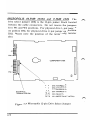
MICROPOLIS 44.5MB 1333A and 71.3MB 1335:
The
drive select jumper (DS) is the 12-pin jumper block located
between the cable connectors. Do not remove the jumpers
from WI and W2 positions. For physical drive 1, put jumper
on position DSl; for physical drive 2, put jumper on position
DS2. Please note the position of the terminating resistor
also.
o
D
J2
PIN 1
o
COMPONENT SIDE
J1
o
DS4 (ADDRESS 4)
INTERFACE
TERMINA TOR RN1
••
DS3 (ADDRESS 3)
••
DS2 (ADDRESS 2)
E.:::!J
DS1 (ADDRESS 1)
[!:3
[!:3
W2 (SELECT)
W1 (WRITE FAULT LATCH)
Figure ID: Micropolis 12-pin Drive Select Jumper
14
MINISCRIBE 42.2MB 3650: The drive select jumper is a
14-pin jumper block located on the left rear of the drive as
you face the rear of the drive. For physical drive 1, place
the jumper on DSO, for physical drive 2, place the jumper on
DSl. Please note the position of the terminating resistor
also.
TERMINATING RESISTOR J2
®®®0®00
~11TTrT
JP1
JP2
JP3
OS3 DS2 DS1
DSO
Figure 1E: Miniscribe 14-pin Drive Select Jumper
15
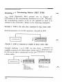
3.2 The Terminating Resistor
Since hard disks can be connected to the controller in a
daisy-chain fashion, the drives have a resistor called a
terminating resistor.
The resistor can either be removed
(Seagate, Micropolis and Miniscribe drives) or disabled
(NEe 5146) so you can turn the terminator on and off,
depending on the configuration of your computer. To
locate the terminating resistor of your drive, refer to
Figures 1A through 1E. The last drive connected to the
daisy-chain cable must have its terminating resistor installed.
If the controller has two drives connected to it, the drive
attached to the middle of the daisy-chain cable must have its
terminating resistor removed.
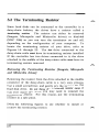
Removing the Terminating Resistor (Seagate, Micropolis
and Miniscribe drives):
Removing the resistor from the drive attached to the middle
connector of the daisy-chain cable is a very easy process.
Use a small screwdriver, and gently pry the resistor off the
hard disk drive. Do not throw the terminating resistor away, if
you ever move the drive, you may need to reinstall the
terminating resistor. For this reason, put the terminating
resistor in a safe place.
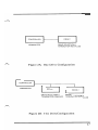
Note the following figures to see whether to install or
remove the terminating resistor.
16
DRIVE 1
CONTROLLER DRIVE SELECTION=1
TERMINATOR INSTALLED
TERMINATED Figure 2A: One Drive Configuration
CONTROLLER
TERMINATED
I
I
I
DRIVE 1 DRIVE SELECTION~1
TERMINATOR REMOVED
L
DRIVE 2
DRIVE SELECTION~2
TERMINATOR INSTALLED
Figure 2B: Two Drive Configuration
17
Disabling the Terminating Resistor {NEe 5146}:
The 8-pin dipswitch SWI pointed out lfi Figure Ie
determines if the terminating resistor is on or off. Whether
the terminating resistor is on or off depends on how it IS
cabled to the controller. Refer to the following examples:
Example 1: 5146 is the only drive connected to daisy-chain cable
Switch positions 2 to 8 ON; position 1 should be OFF.
I
0
N
CONTROLLER
t
I
~~~~~~~~
12345678
Example 2: 5146 is connected to middle of daisy-chain cable
Switch positions 1 to 8 OFF on the drive connected to
middle connector of daisy-chain cable; switch positions 2 to
8 ON on the drive connected to the end connector of daisy
chain cable.
~
I
CONTROLLER
~
0
N
t
I
~~~~~~~~
~~~~~~~~
12345678
12345678
SW1
DRIVE 1
(MIDDLE OF
DAISY CHAIN)
TERMINATOR OFF
18
I
DRIVE 2
TERMINATOR ON
Section 4: Controller Configuration The positIOn of the jumper shunts at location SWI of the
hard disk controller (model number EV-390 or EV-391)
determines the physical characteristics of the drive(s)
attached to the controller. These physical characteristics
include very important drive specifications, such as the
capacity (in megabytes), and how many heads and cylinders
the drives have. You need to place the jumper shunt on the
pins at SWI according to the type of drive(s) you are
installing.
~
WARNING: Circuit boards are sensitive to static electricity,
which could damage their delicate electronics. You can pick up
a static charge in dry weather or walking on carpeted floors.
To rid yourself of the static charge, touch the system chassis
before you handle your board, and handle the board by the
edges only.
19
4.1 Controller Description
The EVERDISK subsystem comes mostly with the EV-391
controller board. The board is two-third sized, and is NOT
AT-compatible. The EV-391 controller uses MFM encoding,
which records 17 sectors per track on a hard disk
compatible with the ST506 specification. The EV-391 can
operate two drives, even if the drives have a different
number of heads and cylinders. The EV-391 has an optional
37-pin connector on the board's mounting bracket, which
allows the installation of an external hard disk drive
subchassis compatible with the ST506 standard.
Some EVERDISK subsystems are delivered with the EV-392
controller board. The EV-392 is similar in size to the EV
391 controller, but the EV-392 uses RLL (2,7) encoding,
which records 26 sectors per track on a hard disk
compatible with the ST412 specification. Drives connected
to the EV-392 MUST be RLL (2,7)-qualified.
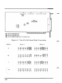
EVERDISK subsystems can also be delivered with the EV
390 controller. The function of the EV-390 is similar to the
EV-391, but the EV-390 is a full-sized controller board that
can also control up to four 360KB-capacity floppy disk
drives in addition to controlling two hard disk drives. The
floppy disk section can be disabled by removing the jumper
shunt from the jumper block marked WlO (see Figure 4 for
the location of the WlO jumper block on the EV-390 board).
20
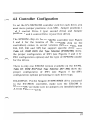
4.2 Controller Configuration
To set the EV-390/391/392 controller card for each drive, you
must move jumper positions 1-4 on SW1. Jumper positions 1
and 2 control Drive 2 (your second drive) and Jumper
positions 3 and 4 control Drive 1 (your first drive).
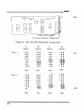
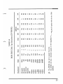
The EPROM chip on the EV-390/391 controller (see Figure
3 and 4 for the location of the EPROM chip on the
controllers) comes in several versions (labeled 3.92A, 3.93,
3.94, 3.95, 3.96 and 3.97) that support specific drive types.
Table 1A: ROM BIOS Disk Type Selection (EV390/391) shows
the proper configuration of SW1 (see Figures 3 and 4 for
SW1 configuration options) and the type of EPROM needed
for the drives.
There is only one EPROM version available on the EV-392.
Table 1B: ROM BIOS Disk Type Selection (EV-392) shows the
proper configuration of SW1 (see Figure 5 for SW1
configuration options) pertaining to each drive type.
EXAMPLE: For the Seagate ST4096 80MB drive connected
to the EV-390/391 controller, make sure the EPROM is
labeled "3.95," and make sure no jumpers are installed (option
A from Figures 3 and 4).
21
c:::::J c:::::=:J
J3
J2
B ~~
B
B0
J1
SW1
J4
OPTIONAL EXTERNAL CONNECTOR
Figure 3: The EV-391 Hard Disk Controller
Drive 1
Drive 2
22
C
Option
D
A
B
Option
Option
5 ••
5 ••
6 ••
5 ••
5 ••
6 ••
6 ••
6 • •
7 ••
7 ••
7 ••
7 ••
8 ••
8 ••
8 ••
8 ••
4 • •
4 ••
4~
3 ••
3~
3 ••
4~
3~
2 ••
2 ••
2 ••
2· •
1 • •
1 • •
1 • •
1 • •
SWl
SWl
SWl
SWl
5 ••
5 ••
5 ••
5 ••
6 ••
6 ••
6 ••
6 ••
7 ••
7 ••
7 ••
7 ••
8 ••
8 ••
8 ••
4 • •
4 ••
4 ••
3 ••
3 ••
3 ••
8 ••
4 ••
3 ••
2 • •
2 ••
2~
1 ••
1~
1 • •
2r!::!1
1 I!::!]
SWl
SWl
SWl
SWl
Option 1'-'"
J6
DRIVE A & B
c::=:::J [===:J
J3
=======:::J
CI
J2
Jl
/
J5
wloD
U23
OPTIONAL EXTERNAL CONNECTOR
Figure 4: The EV-390 Hard Disk/Floppy Disk
Controller
Option
B
Option
C
Option
5 ••
5 ••
5 ••
5 ••
6 ••
6 ••
6 ••
6 ••
7 ••
A
Drive 1 Drive 2 7 ••
7 ••
7 ••
8 ••
8 ••
8 ••
4 • •
4 ••
3 ••
2 ••
3l:!::!]
2 ••
4l:!::!]
3 ••
1 • •
D
Option
8 ••
4~
2 ••
3l!::!]
2 ••
1 • •
1 ••
1 • •
SWI
SWI
SWI
SWI
5 • •
5 ••
5 ••
5 ••
6 • •
6 ••
6 ••
6 ••
7 ••
7 ••
7 ••
7 ••
8 ••
8 ••
8 ••
8 ••
4 ••
4 ••
4 ••
4 ••
3 ••
3 ••
3 ••
3 ••
2 ••
2 ••
2I:!:!]
1 • •
1l:!::!]
2l:!::!]
1 • •
SWI
SWI
SWI
SWI
1 C!::!]
23
J3
J2
L
J1
___---'
r£:!l!]
W8
W4
W3
W9[;j
l!::!1!I
J4
[!:!]
W6~
J1J2J3J4-
34
20
20
37
PIN
PIN
PIN
PIN
CONNECTOR
CONNECTOR
CONNECTOR
FEMALE BRACKET CONNECTOR
Figure 5: The EV-392 Hard Disk Controller
Option
A
Drive 1
Drive 2
: : : : : :[;][;]
56781234
B
c
: : : : : : : [;J
• • • • • 1-1. •
5
5
678
• 6• •7 •8 •1 l!J.
•
234
• • • • 1-1. • •
• • • • •• • •
• • • • • •2 3
• 4•
5 6
5678
24
234
• • • • • • fil·
I.!.I •
5678
D
• • • • 1-11-1. •
• 6• •7 8• 1
1.!Jl!J.
•
234
5
234
•5 •6 •7 •8 l!J.
•
1 2•
34
•••• ••••
• • •7 •8 • •2 3
• 4•
~ 42.2
42
10.7
21.4
42.8
21.4
31.9
42.5
80.2
10
44.5
71.3
MB
5
8
4
6
8
2
4
6
4
5
5
9
Heads
1024
1024
306
809
615
615
615
820
615
733
977
1024
Cyl
NS
NS
A
NS
NS
B
e
NS
e
NS
D
NS
B
e
NS
e
D
•
D
NS
3.93
NS
NS
A
NS
NS
3.92A
B
NS
e
D
e
NS
NS
A
B
NS
NS
NS
NS
3.95
NS
e
D
e
NS
NS
NS
NS
NS
A
NS
EPROM
3.94
TABLEIA
ROM BIOS Disk Type Selections (EV-390/391)
)
NS
NS
NS
NS
e
NS
e
D
NS
NS
B
A
3.96
e
NS
e
D
•
D
NS
B
NS
NS
NS
A
NS
3.97
)
The EPROM chip will not support this drive.
The ST4051 will have a formatted capacity of 31.9 megabytes when using the D option with the the 3.92A
EPROM.
1333A
1335
612
3650
5146
ST213
ST225
ST251
ST4026
ST4038
ST4051
ST4096
Micropolis
Micropolis
Microscience
Miniscribe
NEe
Seagate
Seagate
Seagate
Seagate
Seagate
Seagate
Seagate
~S:
Model
Manufacturer
)
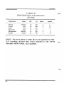
TABLEIB ROM BIOS Disk Type Selections (EV-392) Manufacturer
Model
MB
Cyl
Heads
Tandon
Vertex
Priam
Miniscribc
Microscicncc
Seagate
TM755
V150
V170
3425
HH725
ST238
65
65
92
31
31
32
981
981
987
612
612
615
5
5
7
4
4
4
Option
A
A
B
C
C
D
NOTE: The drives listed in Table 1B are all qualified for RLL
(2,7) encoding; all hard disk drives attached to the EV-392
controller MUST be RLL (2,7) qualified.
26
-"'""
Section 5: Physical Installation Because of the large number of procedures needed to install
a hard disk drive in your system, we strongly urge you to
read through this section thoroughly before you install the
drive. This section contains information on how to install
internal and external drives.
NOTE: Since the EVERDISK subsystem requires extensive
amounts of work inside the system unit during the physical
installation process, we suggest having a reputable dealer do the
installation for you. Also, IBM PC owners should consider
upgrading the power supply for the hard disk subsystem to
work properly.
5.1 Installing the Controller
1. Remove the hard disk drive, controller board, cables,
mounting hardware and the EVERDISK software
diskette from the carton. Save the packaging materials,
boxes and payment receipts.
NOTE: If you ever return your EVERDISK hard disk
subsystem to Everex Systems for any reason without
proper packaging, your warranty may be affected. Please
read the warranty card included in the packaging; the
warranty will not be in effect until the warranty card is
filled out and returned to Everex Systems.
;---.
2. Turn OFF the system and remove all power cables
from the system. Clear an area around your computer
to leave plenty of room to work.
27
3. Remove the system cover (see Appendix 1 on how to
remove the system cover).
4. Remove the hard disk controller from the anti-static
bag; then make sure the controller is configured for the
drive you have (see Section 4.2 for instructions on
configuring the controller).
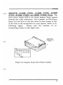
5. Locate an available expansion slot cover nearest the
floppy disk controller and remove the screw that holds
the expansion slot cover in place; lift the slot cover off.
Be sure to save the screw, as you will use it to secure
the controller later.
,
e:b
I
Figure 6: Removing the Expansion Slot Cover
28
1"""'\
6. Attach the 34-pin cable to the J1 connector and the 20
pin cable to the J2 connector. Make sure you align the
colored stripe on the cables to the silkscreened "1" on
the controller.
COMPONENT SIDE
Figure 7: Attaching the Cables to the Controller
7. Insert the controller into the available expansion slot,
making sure the gold edge connectors are fully seated
into the expansion slot.
--FLOPPY DISK CONTROLLER
Figure & Installing the Controller Board
29
5.2 Internal Drive Installation
5.2.1 One Internal Drive
1. Remove the hard disk controller from the anti-static
bag and confirm the controller is configured for the
drive you have.
See Section 4.2 for controller
configuration instructions.
2. Turn OFF the system and remove all power cables
from the system. Clear an area around your computer
to leave plenty of room to work.
3. Install the controller according to the instructions
Section 5.1.
4. Make sure the drive select switch and terminating
resistor on the drive have been adjusted according to
the instructions in Sections 3.1 and 3.2.
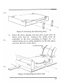
5. Install the mounting bars onto the disk drive using the
flat head "A" screws as shown in Figure 9.
30
10
Figure 9: Attaching the Mounting Bars
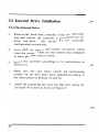
6. Insert the drive partially into the drive space with the
metal cover face up. Connect the cables from the
controller to the drive according to Figure 10. The
colored stripe on the cables should be on the left side as
you face the front of the drive.
Figure 10: Installing the Hard Disk
31
7.
Connect the 4-pin power cable from a power source
(either the computer's power supply or an additional
power supply) to the drive.
8. Slide the drive completely into the drive space, and
connect the provided pan head screws to secure the disk
drive mounting bar to the system chassis (see Figure 10).
DO NOT over-tighten the screws or use long screws;
doing so may damage the drive.
9. DO NOT change the switch settings on your system
motherboard unless you removed the floppy disk drive
and replaced it with the hard disk drive; in this case,
refer to your system's manual on how to reset your
motherboard dipswitches for one floppy drive.
10. Reinstall disconnected cables and turn ON your system
with the DOS diskette in drive A.
WARNING: Don't touch the components inside the system
when the computer is ON with the system cover removed;
you may damage the components, and some parts can
cause electrical shock.
11. Format the hard disk using the instructions in Section 6
of this manual.
32
".........,
12. When the drive is formatted and working properly, turn OFF the system and reinstall the system cover.
33
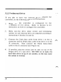
5.2.2 Two Internal Drives
If you plan to have two internal drives attached the
controller, use the following additional instructions:
1. Make sure the controller is configured for the
installation of two drives. Refer to Section 4.2 for
instructions on how to configure the controller.
2. Make sure the drive select switch and terminating
resistor on each internal drive are adjusted according to
instructions in Section 3.1 and 3.2.
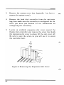
3. Connect the 20-pin data cable from drive 1 to the 12
connector and the 20-pin data cable from drive 2 to the
13 connector. Then connect the 34-pin daisy-chain
cable to the 11 connector (see Figure 11).
4. If possible, place the drives side by side on top of the
floppy drive or a tape drive. DO NOT try to stack two
hard disk drives on top of one another, as this may cause
the system to overheat!
34
r-.,
5. Connect the 20-pin and 34-pin cables to the hard disk
drives. The cable attached to 12 connects to drive 1, and
the cable attached to 13 connects to drive 2. Make sure
the colored stripe on the cables connect is on the left
side as you face the front of the system. The end
connector of the daisy-chain cable should be connected
to drive 2; the middle connector should be connected to
drive 1. Refer to the following figure.
~/
I
DRIVE 2 DRIVE 1
Figure 11: Installing Two Hard Disk Drives
35
6. Connect the power cables to the drives; use a "Y" power
cable if necessary.
7. Reinstall all cables and turn the computer ON.
8. Follow the instructions in Section 6 to format the two
hard disk drives.
Note that your second drive is
normally addressed as the "D" drive.
9. When the drives are tested and working, turn OFF the
system and reinstall the system cover.
36
"....."
~
5.3 External Drive Installation
5.3.1 Installing One External Drive
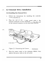
1. Follow the instructions for installing the controller
board in Section 5.1.
2. Plug one end of the shielded round cable to the
external connector on the controller, and the other end
to the external connector on the hard disk subchassis.
Figure 12: Connecting the Controller to Subchassis
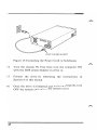
3. Plug the power cable to the subchassis FIRST, then
plug in the power cable to the wall outlet.
37
"
PLUG THIS END IN FIRST
Figure 13: Connecting the Power Cord to Subchassis
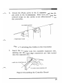
4. Turn the chassis ON first; then turn the computer ON
with the DOS system diskette in drive A.
5. Format the drive by following the instructions
Section 6 of this manual.
6. Once the drive is formatted and working properly, turn
OFF the system and replace the system cover.
38
III
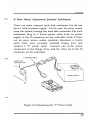
A Note About Unpowered External Subchassis:
There are some external hard disk subchassis that do not
have a built-in power supply. In this case, the power comes
from the system through the hard disk controller. For such
subchassis, plug in a 4-wire power cable from the power
supply to the J5 connector on the controller board; if there
are no spare power cables available, disconnect a 4-wire
cable from your currently installed floppy drive and
connect a "Y" power cable. Connect one of the 4-wire
connectors to the floppy drive, and the other one to the J5
connector on the controller.
POWER SUPPLY
Figure 14: Connecting the "Y" Power Cable
39
5.3.2 Installing Two External Drives
The procedures for installing two external drives are similar
to installing one external drive; however, the two external
drives are two half-height drives encased in a full-height
subchassis with its own power supply.
Before you install the two-drive subchassis, make sure you
configure the hard disk controller board so two drives are
usable by the controller (see Section 4). Then use the
instructions in Section 5.3.1 to connect your two-drive
subchassis to your system.
WARNING: DO NOT open the two-drive external hard disk
subchassis; the drives have already been properly configured as
drive 1 and drive 2. Also, many internal parts of the subchassis
can produce electrical shock.
NOTE: The second drive will be recognized as drive "D".
40
Section 6: Formatting the Hard Disk r-,> Unlike floppy diskettes, formatting a hard disk drive is a
three-step process: physical formatting, drive partitioning, and
logical formatting.
Physical formatting arranges the
information on the disk media and marks the bad sectors on
the hard disk. Disk partitioning defines a disk space where
information can be stored. Logical formatting prepares the
partition with information so that DOS can read and write
data to and from that partition.
Everex Systems has included with your EVERDISK hard
disk subsystem the EVERDISK utility diskette (Version 3.0
or later), which contains programs that will perform the
three steps needed to format your hard disk drive. You will
also need a DOS system diskette in order to format your
hard disk.
NOTE: Before you begin to format your hard disk, please note
the list provided by the drive manufacturer which lists the bad
tracks on the drive. This list is usually a computer print-out
taped to the drive itself; often it is a sticker on the metal side
of the drive. KEEP THIS LIST, as you will need it to format
the drive.
41
6.1 For Older IBM PC Models
Some early models of the IBM PC (the PC 1) do not contain
the ROM BIOS codes which allow you to boot DOS directly
from the hard disk. For these systems, a software patch is
necessary for the PC to recognize the hard disk drive.
Everex Systems provides you with such a software patch.
This patch is called EVEREXl.EXE and is located on the
EVERDISK software diskette that accompanies your hard
disk subsystem.
On the left hand side of your IBM PC motherboard (near
the speaker) is a white label which indicates the model
number of the Pc. If it is labeled 16K - 64K CPU, you have
a PC 1, if it is labeled 64K - 256K CPU, you have a PC 2.
To Install the EVEREX1.EXE Patch:
1
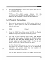
Copy the file EVEREXl.EXE from your EVERDISK
utility diskette to your DOS system diskette.
2. Type in the following lines (DO NOT do this step if
you already have an AUTOEXEC.BAT file on your DOS
system diskette; instead use a text editor to enter the
line everex1 in the AUTOEXEC.BAT file):
copy con: autoexec.bat
everexl [F6] 42
[Enter]
[Enter]
[Enter]
,-....,
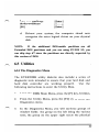
3. Press [Ctrl]-[Alt]-[Del] to reboot the system; this will run
the EVEREXl.EXE file.
NOTE:
The
DOS
system
diskette
with
this
AUTOEXEC.BAT file must be run each time the system is
booted for the computer to access the hard disk drive.
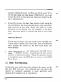
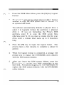
6.2 Physical Formatting
1. Boot up the system with the DOS system diskette in
drive A. Then replace it with the EVERDISK utility
diskette and type:
DISK [Enter]
2. From the DISK Main Menu, press the [F2] key, Physical
Format, to begin the physical formatting process.
3. You will see the following menu fields: Enter physical
disk number, Enter number of cylinders in disk, Enter number
of heads in disk, Enter disk interleave factor (1 to 9), and
Do disk media test after format (YIN). Use the up and
down cursor keys to move between the fields.
As the physical description of the hard disk drive is
determined by the SW1 settings on the EV-390/391/392
controller, you cannot adjust the total number of
cylinders and heads in the drive.
For the disk interleave factor, we suggest entering the
43
number 5 (default factor for pes and XTs); enter "Y" in
the Do disk media test after format (YIN) field if you need
to test the drive to find any bad tracks not listed by the
drive manufacturer.
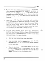
4. Press [F2] to enter the Bad Track window field; using the
list provided by the drive manufacturer, enter the entire
bad track list in this field. Enter one value at a time
followed by the [Enter] key; for example, if the drive
has a bad track listed at cylinder 400, head 2, you would
type:
400[Enter ]2[Enter]
If you want to insert any bad tracks, press the [F5] key;
if you want to delete any bad tracks, press the [F6] key
after placing the cursor on the bad track entry you
want deleted.
5. After entering all the bad tracks, press the [F8] key to
begin the physical format. Formatting will take several
minutes so please be patient. When the physical format
is completed, press the [FlO] key to return to the DISK
Main Menu.
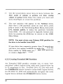
6.3 Disk Partitioning
Partitioning your hard disk drive defines the space on the
disk that DOS will use. The software lets you select the
number of cylinders allocated to each partition; each
physical drive supports up to 4 partitions.
44
~
6.3.1
Creating Primary DOS Partition:
1. From the DISK Main Menu, press the [F3] key, Partition
Disk.
2. Press the [F3] key, Create DOS Partition.
3. This initial partition on the disk must contain the DOS
system files so it can self-boot; press the [F3] key, Create
Primary DOS Partition.
4. You will see these window fields:
Maximum number of available cylinders
Maximum cylinders allowed in partition
Enter number of cylinders in partition
Enter starting cylinder of partition
aaa
bbb
ccc
ddd
Where:
aaa bbb ccc ddd represents the largest free space on the drive.
represents the maximum size of a partition. If
the drive is less than 32 megabytes in capacity,
bbb will equal the aaa value; if the drive is larger
than 32 megabytes, bbb will represent the drive
space equivalent to the 32 megabyte limit
imposed by DOS.
represents the number of cylinders you want in
the partition; to make sure the drive can self
boot, do not exceed the suggested ccc value.
represents the starting cylinder of the partition;
since you are partitioning the first partition
where yout DOS system files will be stored, the
ddd value should be O.
45
5. Use the up and down cursor keys to move between the
Enter number of cylinders in partition and Enter starting
cylinder of partition fields. Enter the values you want, and
press the [F8] key to create the partition.
6. The new partition will appear in the Partitions menu.
Now that a DOS partition exists on your drive, press
[F9] to return to the Partitioning Main Menu, then press
[F4], Activate partition, to make the partition bootable
from DOS. You can proceed to logically format your
drive by pressing the [FlO] key to return to the DISK
Main Menu.
NOTE: You must activate your Primary DOS partition for
the drive to be bootable from DOS!
If your drive has a capacity greater than 32 megabytes,
you have two options available to make the rest of the
drive usable by DOS: create an Extended DOS partition,
or create a Super DOS partition.
6.3.2 Creating Extended DOS Partition
An Extended DOS partition contains one or more "sub
partitions" called Logical drives, with each Logical drive up
to 32 megabytes in size. For DOS 2.0 to 3.2, you will need
the EVDISK.SYS device driver to access these logical drives;
for PC-DOS 3.3, DOS will automatically recognize the extra
logical drives without the EVDISK.SYS device driver.
46
1. From the Partitioning Main Menu, press [F3], Create
DOS Partition, then press [F4], Create Extended DOS
Partition.
2. You will then see these window fields:
Maximum number of available cylinders
Maximum cylinders allowed in partition
Enter number of cylinders in partition
Enter starting cylinder of partition
3. aaa
bbb
ccc
ddd
Use the up and down cursor keys to move between the
Enter number of cylinders in partition and Enter starting
cylinder of partition fields. Enter the values you want, and
press the [FS] key to create the partition.
4. The Partition Menu window will then be replaced by a
new Create Logical DOS Drive window with the following
fields:
Maximum available Extended partition space
Maximum cylinders allowed in Logical drive
Enter number of cylinders in Logical drive
Enter starting cylinder of Logical drive
eee fff ggg hhh Where:
eee fff represents the space available in the Extended
DOS partition.
represents the maximum number of cylinders
allowed for the Logical drive within the
Extended DOS partition. If the Extended DOS
partition is less than 32 megabytes in size, the fff
47
ggg
hhh
5. value will equal the eee value; if the Extended
DOS partition is larger than 32 megabytes in
size, the m value will be equivalent to a Logical
drive that is 32 megabytes in capacity.
represents the number of cylinders you want in the Logical drive. represents the starting cylinder of the Logical drive in the Extended DOS partition. Enter the ggg and hhh values, and press the [FS] key to
create the logical drive.
6. If there is room left in the Extended DOS partition for
another Logical drive, you will be prompted to continue
creating Logical drives until you have no more space to
create a Logical drive in the Extended DOS partition.
7. You will notice in the Partitions menu two new partition
types: Ext-DOS, which is the Extended DOS partition
you created, and Log-DOS, which are the logical drives
inside the Extended DOS partition.
S. Press the [FlO] key to return to the DISK Main Menu
and proceed to Section 6.4 to logically format the
partitions in your drive.
6.3.3 Creating Super DOS Partition
A Super DOS partition, like the Extended DOS partition,
allows DOS to access a high-capacity drive; but unlike an
Extended DOS partition, Super DOS partitions define
logical drives that are larger than the normal 32 megabyte
48
~
,,-...., DOS limit, with a maximum limit of 285 megabytes per
Super DOS partition. The software allows the definition of
three Super DOS partitions in addition to the Primary DOS
partition; this means you format a physical drive with a
formatted capacity of 887 megabytes! Use the following
instructions to create a Super DOS partition.
1. From the Partitioning program Main Menu, press [F3],
Create DOS Partition, then press [F5], Create Super DOS
Partition.
2. The Partition Menu field displayed is similar to the one
for creating a Primary DOS partition (see Section 6.3.1),
except this time the maximum number of cylinders
allowed in a partition (bbb) will equal the maximum
number of available cylinders (aaa). If you want only
one Super DOS partition, press the [FS] key to create
the partition. You can also create smaller Super DOS
partitions, but there is a limit of 3 Super DOS partitions
per physical drive.
You can have 4 Super DOS
partitions, but then the drive will not be bootable from
DOS.
3. ,.-.., You will notice in the Partitions menu the new Super
DOS partition, named Sup-DOS.
4. Press the [FlO] key to return to the DISK Main Menu;
go on to the next subsection to logically format your
drive.
49
6.3.4 Deleting Partitions
If you
need to delete a partition, use the following
instructions:
1. Choose the physical drive that contains the partition
you want to delete. The software defaults to physical
drive 1; press the [F6] key to select physical drive 2.
2. To select the partition you want to delete, press the [F2]
key to move the cursor to the Partitions menu field, use
the up and down cursor keys to select the partitions you
want deleted, and press the [F2] key again to confirm
your selection. WARNING: If you delete the Primary
DOS Partition, the hard disk drive will not be bootable
from DOS!
3. Press the [F8] key to delete the chosen partition; heed
the warnings about losing data if you delete the partition.
Make sure the partition you delete does not contain
valuable data.
6.4 Logical Formatting
The logical formatting process organizes the data blocks, or
clusters, on the hard disk drive and transfers the DOS
system files to the drive. You will need a DOS system
diskette to complete the logical formatting process.
50
1. From the DISK Main Menu, press the [F4] key, Logical
Format.
2. The program will ask for which physical disk to format,
whether to copy the DOS system files to ;he disk, and
an optional disk label.
The software automatically defaults to physical drive 1;
select 2 to logically format the partitions in physical
drive 2.
If you are formatting the Primary DOS
partition, enter Y to copy the DOS system files;
otherwise enter N. If you want a volume label for your
drive, enter a volume label name up to 11 characters
long.
3. Press the [FS] key to begin the logical format. This
process takes a few minutes to complete so please be
patient.
4. When the logical format is completed, a message will
prompt you to replace the EVERDISK utility diskette
with the DOS system diskette.
5. After you insert the DOS system diskette, press the
[Enter] key to transfer your DOS system files to the
hard disk. Press [Enter] again; you will be prompted to
replace the DOS system diskette with the EVERDISK
utility diskette.
51
6.
If your drive has additional partitions, you must format
each partition separately; to choose a partition to
format, press the [F2] key to move the cursor into the
Partitions menu field, use the cursor keys to select the
partition, and press the [F2] key again to confirm your
selection.
7.
Once you finish logically formatting each partition,
press the [FlO] key to leave the program; a message will
prompt you to press a key to reboot the system. Make
sure the floppy drive door is open, then proceed to
reboot the system. When your system comes up with a
"C>" prompt, your hard disk is ready for use.
8.
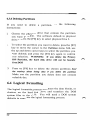
If your disk contains more than one DOS-usable
partition (eg. Extended DOS or Super DOS partitions),
you must create a CONFIG.8YS file in order to use these
extra partitions. To create this file:
52
a.
Boot up your system from your hard disk.
b.
Use the DOS COpy command to copy the file
EVDISK.SYS from the EVERDISK utility diskette
to the hard disk.
c.
Type in the following lines (DO NOT do this step
if you already have a CONFIG.8YS file on your
hard disk; instead use a text editor to enter the line
device=evdisk.sys in the CONFIG.8YS file):
,,-....
,,-....
copy con: config.sys
device=evdisk.sys
[F6] [Enter]
[Enter]
[Enter]
d. Reboot your system; the computer should now
recognize the extra logical drives on your physical
disk.
If the additional DOS-usable partitions are all
NOTE:
Extended DOS partitions and you are using PC-DOS 3.3, you
can skip step #7 since the partitions are directly supported by
this version of DOS.
6.5 Utilities
6.5.1 The Diagnostics Menu
The EVERDISK utility diskette also includes a senes of
diagnostic tests intended to ensure that your hard disk and
hard disk controller are working properly.
Use the
following instructions to enter the Utility Menu.
1. From the DISK Main Menu, press the [FS] key, Utilities.
2. From the Utility Menu, press the [F4] key to enter the
Diagnostics menu.
3. In the Diagnostics Menu, you will see three groups of
window fields: the group on the left listing the various
tests; the group on the upper right selects the physical
53
drive to test, whether to do a continuous drive test, and
the duty cycle percentage value (100 percent means
testing the drive at maximum performance capabilities);
and the group on the lower right displays the test status.
4. Move the cursor with the cursor keys to the upper right
group; select the physical drive you want to test, select
whether or not to do a continuous test, and select the
duty cycle.
NOTE: For the duty cycle, we do not recommend entering
100 percent if you choose to do a continuous test, as this
may damage the drive if the continuous test is done over a
long period of time.
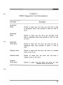
5. 54
Move the cursor to the left menu field, and use the up
and down cursor keys to select the test you want to run.
Table 2 below is a description of each test.
TABLE 2
DISK Diagnostic Test Descriptions
Test Name
Sequential
Write
Sequential
Read
Sequential
Write-Read
Description
Checks to make sure the drive can write data to disk
in sequential order from cylinder 0, head 0 to end of
drive.
Checks to make sure the drive can read data from
disk in sequential order from cylinder 0, head 0 to end
of drive.
Checks to make sure the drive can write and read in
sequential order from cylinder 0, head 0 to end of
drive.
Random Write
Checks to make sure the drive can write to a random
track on the drive.
Random Read
Checks to make sure the drive can read from a
random track on the drive.
Random
Write-Read
Checks to make sure the drive can write and read
data to and from a random track on the drive.
55
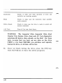
Controller
Checks to make sure basic operation of drive and
controller are working properly.
Seek Checks to make sure the read/write head assembly
works properly.
Drive Ready Checks to make sure the drive is ready to accept and
execute commands.
All Tests Runs all the tests listed above.
WARNING: The Sequential Write, Sequential Write-Read,
Random Write, Random Write-Read, and All Tests diagnostics
selections will destroy data already on the disk! For these
tests, we urge that you back up any data on the drive
FIRST or run them BEFORE you partition and logically
format the drive, or all data will be lost.
6. 56
Once you finish testing the drive, press the [F9] key,
then the [FlO] key to leave the utility programs.
6.5.2 SHIPDISK.EXE Whenever you need to move your system and/or hard disk,
you should move ("park") the read/write head on the hard
disk at an area always void of data (the so-called landing
zone). This is analogous to securing the tone arm of a stereo
turntable.
To park the read/write head, use the
SHIPDISK.EXE program on the EVERDISK utility diskette.
To Park the Read/Write Heads:
1--...,
1. Insert the EVERDISK utility diskette in drive A.
2. Type:
SHIPDISK r"'\ [Enter]
3. The program will ask you for a drive number (1-8).
Enter 1 for physical drive 1, enter 2 for physical drive 2.
If two drives are connected to your system, you must
run this program twice to park the heads on both
drives; park the read/write heads on physical drive 2
first, then park the heads on physical drive 1.
4. When the head is parked, a disk is ready to ship message
will appear. The drive(s) are now ready to be moved.
NOTE: Some drives do not need to run SHIPDISK.EXE as the
drive will automatically park the read/write head mechanism
upon turning off the system.
57
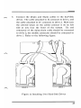
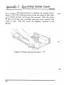
Appendix 1: Removing System Cover It is a straightforward process to remove the system cover.
First, remove the holding screws from the edges of the back
panel of the system unit (save the screws). With the front
of the unit facing you, carefully pull the cover towards you
until it stops. Tilt the cover up slightly, and lift it off
gently.
Figure 15: Removing the System Cover
58
Appendix 2: Installing One External
& One Internal Drive
If you have one internal and one external drive, you must
configure the external drive as drive 1 and the internal drive
as drive 2.
Installation Instructions
1. Turn the system OFF.
2. Change the drive select switch so your internal drive is
configured as drive 2 (the external drive is already
configured as drive 1). NOTE: You do not need to
remove the terminating resistor from your internal drive.
3. Change the 20-pin data cable from 12 to 13; the external
drive is connected to the controller via the J4 bracket
connector.
4. Format the external drive as drive "C" and the internal
drive as drive "D". You will boot from the external
drive.
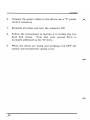
.-., WARNING:
Whenever you install a new hard disk
controller, you must reformat the hard disk drive.
Therefore, back up the data on the original internal hard
disk drive.
5. From now on, you will boot from the external drive
(known as Drive 1) and the internal drive will be
known as Drive 2. If your external drive has its own
power supply, turn ON your external drive first before
you turn on your system.
59
WARNING: DO NOT remove the cover of the external
hard disk drive subchassis; some of the components inside
can produce electrical shock.
60
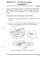
Appendix 3: EV-390 Controller Installation Use the instructions in Section 5 to install the EV-390 Hard
Disk/Floppy controller board. The only change required for
this controller is the installation of a floppy disk ribbon
cable.
To install the hard disklfloppy disk controller:
1. Remove the floppy disk controller card already in your
system.
2. Attach one end of the 34-pin daisy-cable to the J6
connector on the upper left side of the EV-390 board.
Figure 16: Installing the Floppy Disk Cable
61
The daisy-chain cable is keyed to prevent installing the
cable backwards.
The untwisted end of the cable
should be attached to the J6 connector. Make sure to
align the cable with pin 1 on the controller; the color
stripe on the cable should be on the right side as you
see the component side of the controller. (See Figure
16.)
3. Connect the cable's middle connector to drive "B", and
connect the end connector to drive "A". (See Figure 16.)
4. Make sure all connectors are fully inserted; do not use
excessive force to install the connectors.
5. Follow the instructions in Section 5.2 and/or 5.3 to
install your hard disk drive(s).
62
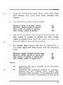
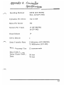
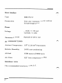
Appendix 4: Controller
Specifications
,,-..,
,.-..,
Encoding Method
MFM (EV-390/391)
RLL (2,7) (EV-392)
Cylinders Per Drive
Up to 1024
Bytes Per Sector
512
Sectors Per Track
17 (EV-390/391)
26 (EV-392)
Head Selects
16
Drive Selects
2
Data Transfer Rate
5 Mbits/sec. (EV-390/391)
7.5 MBits/sec. (EV-392)
Write Precomp Time
12 nanoseconds
Max Cable Length: Daisy Chain Control
Data
20 feet 20 feet 63
Host Interface
Type
IBM PC/XT
Connection
Uses any expansion slot (it will not
fit half-length slots)
Power
Voltage
+5VDC +/- 5% and
+12VDC +/- 10%
Maximum Current
depends of drive type
Environmental Limits
Ambient Temperature
0-550 C (32-131 0 Fahrenheit)
Relative Humidity
10-95% non-condensing
Altitude
0-3000 meters (0-9840 feet)
Air Flow
0.25" from component surface
Interleave factor
The recommended interleave factor is 5.
64
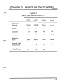
Appendix 5: Hard Disk Specijicatz'ons TABLE 3
Hard Disk Specifications (I)
,"'-'\
Seagate
ST225
Seagate
ST251
Seagate
ST4026
Seagate
ST4038
21.4MB
42.8MB
21.4MB
31.9MB
4
6
4
5
615
820
615
733
Tracks
2460
4920
2460
3665
Encoding
Type
MFM
MFM
MFM
MFM
Transfer Rate
Mbits/second
5
5
5
5
Average
Access (msec)
65
40
40
40
Formatted
Capacity
Heads
Cylinders
65
,,.....,,
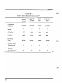
TABLE 4
Hard Disk Specifications (II)
Seagate
ST4051
Seagate
ST4096
NEC
5146
Miniscribe
3650
42.5MB
80.2MB
42MB
42.2MB
5
9
8
6
Cylinders
977
1024
615
809
Tracks
4885
9216
4920
4854
Encoding
Type
MFM
MFM
MFM
MFM
Transfer Rate
Mbitslsecond
5
5
5
5
Average
Access (mscc)
40
28
40
65
Formatted
Capacity
Heads
66
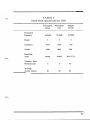
TABLE 5 Hard Disk Specifications (III) Micropolis
1333A
Micropolis
1335
Seagate ST238 44.5MB 71.3MB 315MB 5
8
4
Cylinders
1024 1024 615 Tracks
5120 8192 2460 Encoding
Type
MFM MFM RLL (2,7) Transfer Rate
Mbits/second
5
5
7.5
Average
Access (msec)
30 30
.65
Formatted
Capacity
Heads
67
Appendix 6: Questions &Answers Q.
Do I need to change the dipswitch settings on the
system motherboard?
A.
Normally, you do not need to change the dips witch settings
when you install a hard disk subsystem.
However, if you
removed one of your floppy disk drives so you can install an
internal hard disk drive, check your computer owner's manual
to see how to set the motherboard for one floppy drive
installed.
Q.
When I boot up, the message 1701 hard disk not recognized
comes up. What should I do?
A.
The most likely problem is that your hard disk subsystem is
not securely installed in your computer. Check to make sure
all cables are properly aligned and securely connected; also,
make sure your controller board is securely installed into the
expansion slot.
Q.
After the computer boots up, why does the hard disk
drive motor not spin?
A.
The power cables connected to the hard disk drive are
probably not connected properly. Make sure the power cables
are securely installed to the drive.
68
"""'.
Q. When I boot up, the message invalid drive specification
appears. What should I do?
A. Make sure you followed the hard disk formatting instructions
in Section 6 of this manual properly. If you have a IBM PC
1, you should run the EVEREX1.EXE program each time you
boot up from DOS.
Q. After I format the disk, the drive shows a lot of bad
tracks. What should I do?
A. Make sure you followed the formatting instructions in Section
6 properly; we suggest doing the entire formatting process
again. If you still have a lot .of bad tracks, try removing
some of your expansion boards to determine if an inadequate
power supply is the problem.
Q. Why
does the
periodically?
message
drive
not
ready
appear
A. Your power supply may not be adequate enough to power
your hard disk subsystem and expansion boards simultaneously.
Try removing any unused expansion boards and/or consider
upgrading your power supply.
69
Q. Why is it that after exchanging controllers, the drive
does not work?
A. A
unique physical format is required for each type of
controller. This means if you formatted your hard disk drive
with one type of controller and then replaced the controller
with another type, you must reformat the drive for the newer
controller to work with your drive. Please refer to Section 6
of this manual for instructions on how to reformat your drive.
Note that reformatting your drive will erase all data on the
drive, so back up all data on the drive before you reformat it.
70
71 EVEREX SYSTEMS INC. 48431 MRMONT DRIVE FREMONT, CA 94538 SALES: (415) 683-2100 TECH SUPPORT: (415) 498-1115 FAX: (415) 651-0728 TELEX: 5101000590 MAN-00007-20