1
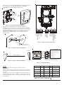
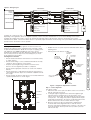
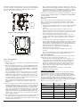
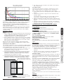
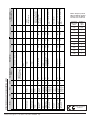
INSTALLATION AND MAINTENANCE INSTRUCTIONS 6500R AND 6500RS REFLECTIVE TYPE PROJECTED BEAM SMOKE DETECTOR GENERAL APPROVED ACCESSORIES 6500-LRK/BEAMLRK The model 6500R is a conventional long range projected beam smoke detector designed to provide open area protection. It consists of a combined transmitter/receiver unit and a reflector. Smoke entering the area between the two components causes a reduction in the signal returned to the receiver. When the obscuration reaches alarm thresholds, selected at the transmitter/receiver unit, the detector generates an alarm signal. Complete blockage of the beam causes a fault signal. Slow changes in obscuration due to a build up of dirt or dust on the lens of the detector are compensated for by a microcontroller that continuously monitors the signal strength and periodically updates the alarm and fault thresholds. When the selfcompensation circuit reaches its limit, the detector generates a fault signal, indicating the need for service. After local testing is complete, the yellow LED will blink a pattern to indicate the level of drift compensation employed during the test (see Blinks Output by Yellow LED table at back of manual). The model 6500RS includes an integral servo controlled calibrated test filter, which allows automatic remote alarm testing. Long Range Kit comprising three additional 20cm x 20cm reflectors, which may be mounted in a square with the supplied reflector, permitting the detector to be used for ranges from 70m to 100m. 6500-MMK/BEAMMMK Multi-Mounting Kit allowing the 6500 to be mounted to ceilings, or to walls where the detector and reflector cannot be mounted within 10° of one another. One kit mounts either the transmitter/receiver unit or reflector. If the transmitter/receiver is mounted on the 6500-MMK/ BEAMMMK, then the 6500-SMK/BEAMSMK must be used. Note that only a single 20cm x 20cm reflector can be mounted using the MMKs: The 6500-LRK/BEAMLRK is not compatible with the MMKs. 6500-SMK/BEAMSMK Surface Mounting Kit for the transmitter receiver (also used in combination with the MMK) to give an additional 43mm depth to assist surface mounting and to permit side entry cabling. Sensitivity: The 6500 must be located in accordance with local standards and guidelines, for example BS5839 part 1. For general information, refer to the application guide for projected beam smoke detectors available on request from your supplier. Mounting Position -30°C to 55°C 10% to 93% Relative Humidity (Non-condensing) Mechanical 230mm x 178mm x 84mm 253mm x 193mm x 84mm 1mm² to 2.5mm² ±10° Horizontal and Vertical Voltage Range: 6500R: 10.2 to 32 VDC 6500RS: 15 to 32VDC 17mA at 24 VDC 38.5mA at 24VDC 8.5mA at 24 VDC 500mA peak 0.5A at 30 VDC Voltage: 15 to 32VDC dependant on supply Current: 6mA to 15mA, Limited by 2.2KΩ Resistor Avg. Standby Current: Max. Alarm Current: Max. Fault Current: 6500RS Test Mode: Relay Contact Ratings: Remote Output (Alarm): PARTS LIST Description Transmitter/Receiver Unit Paintable Trim Ring Reflector (6500REFL) Plug in terminal blocks Instruction Manual Orange Alignment Assistance Label Alarm 0 ohm Shunt Alarm Limiting Resistor 470 ohm Alarm Limiting Resistor 680 ohm Alarm Limiting Resistor 1000 ohm Schottky Diode DB200-01-01 • There must be a permanent clear line of vision between the detector and the reflector. • Reflective objects should be a minimum of 380mm from the line of sight between the detector and reflector to avoid compromise of the protected area by reflected light. • Direct sunlight or strong lights into the transmitter/receiver unit should be avoided. There should be a minimum of 10° between the paths of the light source and the detector beam. • Operation of the detector through panes of glass should be avoided if possible. If it is necessary to pass though glass, the angle between the beam and glass should be set a minimum of 10° off perpendicular, and operation through multiple panes should be avoided. Mounting Quantity 1 1 1 5 1 1 1 1 1 1 1 The transmitter/receiver unit may be mounted directly to the wall, with rear cable entry. The detector base has four primary mounting holes, one in each corner of the base. All four holes must be used to provide secure mounting. In order to mount the detector to the wall, the outer cover must be removed after unscrewing its four retaining screws. 1 I56-2081-013 © System Sensor 2009 FRANÇAIS Dimensions (Without Faceplate): Dimensions (With Faceplate): Wiring: Adjustment Angle: Electrical DEUTSCH Beam detectors require a very stable mounting surface for proper operation. A surface that moves, shifts, vibrates, or warps over time may cause false alarm or fault conditions. Initial selection of a proper mounting surface will eliminate nuisance alarms and fault signals. Mount the detector on a stable mounting surface such as brick, concrete, a sturdy load-bearing wall, support column, structural beam, or other surface that is not expected to experience vibration or movement over time. DO NOT MOUNT the beam detector on corrugated metal walls, sheet metal walls, external building sheathing, external siding, suspended ceilings, steel web trusses, rafters, nonstructural beam, joists, or other such surfaces. The reflector has a much greater tolerance to movement than the transmitter/receiver, hence in cases where only one stable mounting surface as defined above can be used, the transmitter/receiver unit should be mounted to the stable surface. See specifications for maximum permissible angular misalignment; movement outside these limits may cause nuisance alarms and faults. Mounting Considerations ESPAÑOL Environmental Temperature Range: Humidity: Location ITALIANO Maximum angular misalignment: Remote test and annunciator accessory that enables the detector to be tested remotely, providing test and reset functions, a Red LED to indicate alarm conditions and a Yellow LED to indicate fault conditions. DETECTOR MOUNTING 5 to 70m 70m to 100m using optional 6500-LRK/BEAMLRK Level 1: 25% Obscuration Level 2: 30% Obscuration Level 3: 40% Obscuration Level 4: 50% Obscuration Level 5: 30% to 50% Adjusting (Acclimate) Level 6: 40% to 50% Adjusting (Acclimate) Detector: ± 0.5° Reflector: ± 10° ENGLISH 6500RTS-KEY SPECIFICATIONS: General Range: Please refer to the relevant kit instructions if the transmitter/receiver is to be mounted onto the 6500-SMK/BEAMSMK or 6500-MMK/ BEAMMMK allowing more flexibility for cable entry. WALL MOUNTING SCREW X 4 COVER SCREW X4 Figure 1: Transmitter/Receiver Wall Mounting R L EF EC TO T5 ALARM N.O. ALARM COM ALARM N.O. ALARM COM T4 1234 1234 POWER IN (+) POWER IN (-) POWER OUT (+) POWER OUT (-) R T1 1234 FAULT N.C. FAULT COM REMOTE TROUBLE OUT NOT USED LL WA T2 REMOTE ALARM OUT AUX (-) TEST INPUT RESET INPUT T3 1234 1234 ALARM LIMITING RESISTOR ALARM LIMITING RESISTOR SCHOTTKY DIODE (A) SCHOTTKY DIODE (K) The reflector is mounted directly to the wall using all four of its mounting holes, one in each corner. The reflector must be mounted such that the plane of the reflector is perpendicular to the optical line of sight to the transmitter/receiver unit. The maximum tolerance for nonperpendicular mounting locations is 10°. If this tolerance is not possible, then the MMK should be used, see MMK instructions for mounting details. Figure 3: Detector Terminal Connections ACCEPTABLE MOUNTING LOCATIONS FOR REFLECTOR Figure 2a: Reflector Mounting Guidelines 6500R / 6500RS 10° MAXIMUM GREEN T2-1: REMOTE ALARM OUTPUT ORANGE T3-3: REMOTE TROUBLE OUTPUT BLACK T2-2: AUX (-) RED OPTICAL LINE OF SIGHT T2-4: RESET INPUT YELLOW T2-2: AUX (-) YELLOW T2-3: TEST INPUT SEE 6500RTS-KEY INSTALLATION INSTRUCTIONS FOR 6500RTS-KEY ELECTRICAL RATINGS REFLECTOR Figure 2b: Reflector Mounting Guidelines Figure 4: 6500RTS-KEY Wiring WIRING Note: All wiring must be installed in accordance with local requirements. Warning: Before working on the system, notify the proper authorities that the system is undergoing maintenance and will be temporarily out of service. Wiring connections are made to pluggable terminal blocks, which can accept wire sizes from 1mm² to 2.5mm². For best results screened cable should be used. Refer to the control panel instructions for cable type limitations Signal Name Terminal Normal State Active State Comment Reset Input T2-4 High impedance 0V Momentarily connect to Aux- to operate Test Input T2-3 High impedance 0V Momentarily connect to Aux- to operate Aux- T2-2 0V - Internally connected to Power -ve Remote Alarm Out T2-1 High impedance +24V Via 2.2k ohms current limit resistor Remote Fault Out T3-3 High impedance +24V Via 2.2k ohms current limit resistor Table 0: Use of Input – Output Signals . DB200-01-01 2 I56-2081-013 © System Sensor 2009 Figure 5: Wiring Diagram POWER (+) POWER (-) V IN (+) V OUT (+) V IN (+) VIN (-) V OUT (-) VIN (-) ALARM COM INITIATING ZONE (+) EXTERNAL ALARM LIMITING RESISTOR OR SHUNT INITIATING ZONE (-) OPTIONAL SCHOTTKY DIODE 6500R/6500RS 6500R/6500RS ALARM COM ALARM COM ALARM NO V OUT (+) V OUT (-) ALARM COM ALARM NO ALARM NO ALARM NO A A K CONTROL PANEL FAULT COM K FAULT COM FAULT NC FAULT NC REMOTE FAULT OUTPUT REMOTE FAULT OUTPUT REMOTE ALARM OUTPUT REMOTE ALARM OUTPUT AUX (-) AUX (-) TEST INPUT TEST INPUT RESET INPUT RESET INPUT ZONE EOL DEVICE Terminals T5-1 and T5-2 provide connections used to complete the alarm circuit. A 0 ohm shunt, or current limiting resistor should be fitted depending on the application; these are supplied separately. Refer to the panel manufacturer for correct current limiting resistor values. ALIGNMENT PROCEDURE Warning: When power is initially applied to the detector, before the alignment procedure has been completed, it may enter fault or alarm. To prevent unwanted alarms, disable the zone prior to applying power. Ensure that both the detector and reflector are mounted securely to stable surfaces. • Ensure that all wiring is correct, and that terminal blocks are fully seated into their receptacles on the detector. Complete any wiring dressing to minimize movement to the detector once the alignment procedure is completed. • Ensure that the appropriate reflectors are used for the installed distance. • Ensure that the line of sight between the detector and reflector is clear and that reflective objects are a minimum of 380mm from the line of sight. Ensure that both the detector and reflector are mounted within their operational parameters for off axis angles. • Ensure power to the detector is “ON”. ALIGNMENT MIRROR ALIGNMENT POSITION INDICATOR ALIGNMENT GUN SIGHT DIGITAL SIGNAL STRENGTH READOUT HORIZONTAL ADJUSTMENT OPTICS LOCK-DOWN SCREWS X 2 Figure 7: Alignment Adjustment Locations Step 1. Coarse Alignment See figures 6 and 7. 1. Ensure that both of the optics lock-down screws are loosened so that the optics will move freely. 2. Looking through the alignment mirror at both the alignment gun sight and reflector simultaneously, locate the position of the reflector in the optical sight. Note that initially this step will require some practice. An orange sticky label is supplied, which may be temporarily mounted next to the reflector to aid initial location if the distance between the reflector and the detector is large. ALIGNMENT SENSITIVITY TEST 3. Once the reflector has been located, begin to adjust both the horizontal and vertical alignment knobs so that the reflector becomes centred in the alignment mirror. Caution: If the optics are incorrectly aligned in this step, it will not be possible to proceed with the next step. RESET Figure 6: Switch Locations DB200-01-01 3 I56-2081-013 © System Sensor 2009 FRANÇAIS VERTICAL ADJUSTMENT DEUTSCH • • ESPAÑOL • Disable the zone or system to prevent unwanted alarms before applying power. ITALIANO The alignment of the 6500R is divided into four steps: Coarse alignment, fine adjustment, final gain adjustment, and final verification. It is necessary for all four steps to be executed properly to ensure proper alignment of the product. Pre-Alignment Checklist • ENGLISH Terminals T5-3 and T5-4 are used to connect the optional Schottky diode when used with active end of line monitoring; refer to panel manufacturer for details. Do not fit the diode unless it is specifically required otherwise the functioning of the system will be affected. Diode polarity must be observed for correct operation. Note that the alignment gun site does not give an accurate alignment. It is sufficient only as a starting point for the next step. On completion of the fine adjustment procedure, the alignment gun site may not appear to be centred on the reflector. Note: It may not be possible to achieve a figure close to 90 on the display during the last adjustment iteration. Each time the figure 90 is reached the gain is reduced, making it more difficult to achieve high values. Any number is acceptable, provided it is the highest figure that can be achieved after the final gain adjustment. At this time it is sensible to set the sensitivity of the detector using the sensitivity switch and digital display. See SENSITIVITY SELECTION for further details. Step 3. Final Gain Adjustment EYE See figure 9. In this step, the detector electronically adjusts its internal gain one final time. It is necessary to complete this step with the outer housing installed since the housing will change the amount of light received from the reflector. 1. REFLECTOR Figure 8: Coarse Alignment Procedure 2. SCREW LOCATIONS Note: The housing contains a gasket seal that protects the detector circuitry from corrosion and moisture. To ensure that this gasket performs correctly, it is necessary to tighten all four of the screws holding the outer housing in place evenly. Remove the protective film from the front surface of the outer housing. Note that the outer housing may require cleaning if any residue remains. Use only a soft, damp cloth; do not use any solvents. 3. To initiate the final electronic gain adjustment, the reset switch must be depressed using a small screwdriver or similar tool. Once depressed the yellow LED will begin to blink. On completion, the yellow LED will stop blinking and the green LED will begin blinking, indicating that the gain adjustment was successful. Note: Use caution not to block the line of sight between the detector and reflector in this step. 4. Install the outer aesthetic ring by snapping it onto the outer housing. SCREW LOCATIONS Note: If the outer aesthetic ring has been painted ensure that the paint is completely dry before proceeding with this step. Step 4. Final Verification RESET SWITCH Figure 9: Housing Screw Locations This step is required to insure the detector has been setup correctly and will detect smoke at the proper sensitivity level. 1. With the detector functioning (dependant on the operation of the control panel, this may be indicated by the green LED blinking), completely block the reflector with a non-reflective opaque material, for example this manual. After about 30 seconds, the detector should enter either the fault or alarm condition. If the detector does not enter the fault or alarm condition, there is a problem with the installation. 2. Complete a sensitivity test of the detector as described in SENSITIVITY TESTING below. Step 2. Fine Adjustment See figures 6 to 8. 1. Ensure that no objects are in the line of sight between the detector and the reflector. 2. Depress the Alignment switch once. Both the digital display and the yellow LED should turn on indicating that alignment mode has been entered. The display should begin reading “- -” signifying an electronic gain adjustment. After a few moments the display will indicate a numeric value near 20. Note: If the display reads “Lo” then the detector is not receiving enough light from the reflector. Go back and repeat the course alignment step and verify that the proper number of reflectors is used for the installed distance. The display will continue to read “Lo” until the detector receives enough light from the reflector to continue with the fine adjustment step. SENSITIVITY SELECTION The sensitivity of the detector can be set only when the housing is removed and the detector is not in the fine adjustment step of the alignment mode. To enter the selection mode, press the sensitivity button once (see figure 6). The digital display will illuminate and read the current sensitivity setting in percent obscuration. Press the sensitivity button again to rotate to the next setting. Once the required setting is achieved (See table 1), the detector will exit the sensitivity selection mode if no further switch presses occur. Note: In alignment mode (indicated by the yellow LED and the numeric display) the sensitivity select and test switches are disabled. Sensitivity Setting 3. Once the display shows a number, begin adjusting the horizontal and vertical alignment knobs one at a time to increase signal level on the display. Continue adjusting each axis one at a time going back and forth between them until a peak value is indicated. If a value of 90 is achieved, the detector will reduce its electronic gain. This will be indicated by a “- -” reading on the display. When this happens halt any further adjustment until the display again reads a numeric value. This process may occur more than once during the fine adjustment step. 4. Once satisfied that it is not possible to achieve a higher reading on the display depress the alignment switch to complete the fine adjustment step. The digital display readout will turn “OFF” and the yellow LED will remain “ON”. DB200-01-01 Install the outer housing of the detector. The housing is installed by tightening the four captive screws, one in each corner of the housing. % Obscuration Display Reading Level 1 25 25 Level 2 30 30 Level 3 40 40 Level 4 50 50 Acclimate Level 1 30 to 50 A1 Acclimate Level 2 40 to 50 A2 Table 1: Sensitivity Settings 4 I56-2081-013 © System Sensor 2009 4. The detector can be reset with the reset switch on the detector unit or remote reset. GRAPH 1: SENSITIVITY (%M vs DISTANCE) (Assuming Uniform Smoke Distribution) 7 Test Failure Checks Level 1 6 If the detector fails either the sensitivity or functional test, several steps should be taken before returning the unit to determine if it is faulty, or simply needs to be re-adjusted. These steps include: 5 Obscuration (%/Metre) Level 2 4 1. Verify all wiring connections and appropriate power is applied to the detector. Level 3 Level 4 3 2. Verify that the optical line of sight is free from obstructions and reflective objects. 2 It is imperative that at least 90% of the received light is from the reflector alone, otherwise sensitivity cannot be assured. 1 3. Apply the maintenance procedure in this manual. Repeat the test procedure. If the detector still fails the test procedure proceed with step 4. 0 0 10 20 30 40 50 60 70 80 90 100 Distance (Metres) In addition to the four standard sensitivity selections the detector has two Acclimate settings. When either of these settings is chosen the detector will automatically adjust its sensitivity using advanced software algorithms to select the optimum sensitivity for the environment. The sensitivity will be continuously adjusted within the ranges specified in graph 1. 4. Repeat the alignment procedure in this manual. If the alignment procedure is successful repeat the test procedure. If the detector still fails the test it should be returned for repair. 6500 BEAM DETECTOR: SET-UP PROCEDURE SUMMARY Beam Alignment – ensure power is on Fine Adjustment Initiate using Alignment Switch Continue adjustment using horizontal and vertical thumb screws When the adjustment is complete press the Alignment Switch SENSITIVITY TESTING NOTES: 1. Before testing, notify the proper authorities that the smoke detector system is undergoing maintenance, and therefore the system will be temporarily out of service. Disable the zone or system undergoing maintenance to prevent unwanted alarms. 2. Before testing the detector, check for the presence of the flashing green LED at the receiver, making sure not to disturb or block the beam. If it does not flash and the detector is not in fault or alarm, power has been lost to the detector. Sensitivity Setting Select using Sensitivity Switch Final Verification Use obscuration filters or reflector test card to initiate Fire and Fault signals 2. Carefully clean the reflector. A damp soft cloth with a mild soap may be used. Avoid products with solvents or ammonia. 3. Place the blocking material over the reflector lining it up with the graduated marks that are 10 more than the detector setting in % obscuration. The detector should enter alarm within 1 minute. LINE UP EDGE OF BLOCKING MATERIAL WITH APPROPRIATE OBSCURATION LEVEL The Remote Test Station, 6500RTS-KEY, can be used with the 6500R beam smoke detector. Follow the Installation and Maintenance instructions included with the 6500RTS-KEY for proper use. The 6500RS is equipped with an integral sensitivity test feature that consists of a calibrated test filter attached to a servomotor inside the detector optics. When a test is initiated using the remote test station or local test switch the test filter is moved in the pathway of the light beam. If the correct level of signal reduction is received the detector will enter alarm. If the proper level of signal reduction was not achieved, indicating that the sensitivity of the detector is out of tolerance, the detector will enter the fault condition. Note: This test should satisfy most local periodic maintenance and testing requirements. If the detector fails this test, refer to the Test Failure Checks described above. PAINTING The outer aesthetic ring may be painted using enamel or acrylic paints either by brush or spray. MOVE BLOCKING MATERIAL TO DESIRED AMOUNT OF OBSCURATION Figure 10. Reflector Test Card Procedure Note: 5 Never paint the flat lens surface of the outer housing. I56-2081-013 © System Sensor 2009 FRANÇAIS Functional Testing For periodic maintenance functional testing, the detector can either be tested using the Calibrated Test Filter method, by using the local test switch on the transmitter receiver unit or remotely using the Remote Test Station. DEUTSCH 1. Carefully clean the outer housing lens face. A damp soft cloth with a mild soap may be used. Avoid products with solvents or ammonia. 1. Verify the sensitivity setting of the detector in % obscuration. See the Sensitivity Selection section of this manual for sensitivity determination if sensitivity is unknown. 2. Place the blocking material over the reflector, lining it up with the graduated marks that are 10 less than the detector setting in % obscuration. The detector should not alarm or fault. Keep the material in place for a minimum of 1 minute. ESPAÑOL MAINTENANCE Note: Before cleaning the detector, notify the proper authorities that the smoke detector system is undergoing maintenance, and therefore the system will be temporarily out of service. Disable the zone or system undergoing maintenance to prevent unwanted alarms. Calibrated Test Filter Method The sensitivity of the detector can be tested using an opaque material ( such as this manual ) to cover the reflector by an amount indicated by the graduated scale on the reflector, see Figure 10. ITALIANO Final Gain Adjustment – ensure front cover is fitted Initiate using the Reset Switch Completed when the green LED blinks Detectors must be tested after installation and following periodic maintenance. The sensitivity of the 6500R may be tested as follows: DB200-01-01 ENGLISH Course Alignment Carry out using target eyepiece Adjust using horizontal and vertical thumb screws Total obscuration can be converted to percent per metre assuming uniform smoke density for the entire length of the beam. Graph 1 converts total obscuration to percent per metre for all acceptable sensitivity settings. DB200-01-01 Pittway Tecnologica S.r.l., Via Caboto 19/3, 34147 TRIESTE, Italy 6 Blink until complete Blinks out amount of drift used On until reset of timeout As fault mode Blinks out amount of drift used On Off Off Off Off Off Off On Off Off On Alarm Fault - Drift Comp Elevated Signal Fault – Drift Comp Reduced Signal Fault Signal – Over Range Fault - Beam Blockage Initialisation – Power On InitialisationAlignment Exit Local Test (6500RS) Pass result Local Test (6500RS) Fail result Local Test (6500R) Fail Result Local Test (6500R) Pass result Blink until complete 4 Quick Blinks 2 Quick Blinks 2 Quick Blinks 3 Quick Blinks Off On Off Alignment Off Yellow Off Red Normal Modes Off Off Blink Off Off Off Off Off Off Off Off Off Off On, relative amount of signal 0-99, or “- -“ if auto gain resetting, or “Lo” if signal too low Off Dual Digital Display Readout Blink Off Blink Blink Off Blink Blink Blink Off Off Blink Green OPERATION MODES AND TROUBLESHOOTING GUIDE 6500RTS KEY 6500RTS KEY 6500RTS KEY 6500RTS KEY Depressing RESET switch after alignment Apply Power from discharged state Beam Blockage Increase of reflected signal Long term drift reference out of range Long term drift reference out of range Smoke, Test Filter, 6500RTS KEY Alignment Switch Successful completion of initialisation or detector reset Initiating Means Close Open Open Close Open Open Open Open Open Open Close Open Open On Off Off On Off Off Off Off Off Off On Off Off Remote Alarm Contacts Alarm Close Open Open Close Close Close Open Open Open Open Close Off On On Off Off Off On On On On Off On Off Close Open Remote Fault Contacts Fault Detector remains in alarm until reset If local test fails will already be in fault Detector remains in fault until reset or timeout Detector remains in alarm until reset Remove Blockage Faulty Unit Inspect line of sight between detector and reflector for reflective objects in path Clean detector and reflector Sunlight into detector or reflector Re-align detector Comments and Troubleshooting Tips Blinks Output by Yellow LED and Remote Trouble Output once the Device has Passed a Local Test Percent the detector has drifted Number of blinks output <10% None <20% 1 <30% 2 <40% 3 <50% 4 <60% 5 <70% 6 <80% 7 <90% 8 <100% 9 0832-CPD-0323 EN54-12 I56-2081-013 © System Sensor 2009