1
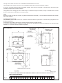
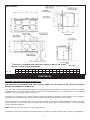
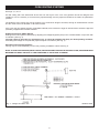
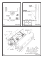
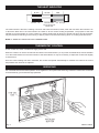
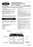
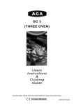
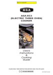
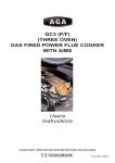
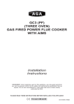
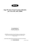
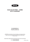
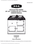
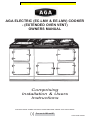
Models up to August 2007
AGA ELECTRIC (EC-LMV & EE-LMV) COOKER
- (EXTENDED OVEN VENT)
OWNERS MANUAL
Comprising
Installation & Users
Instructions
PLEASE READ THESE INSTRUCTIONS BEFORE USING THIS APPLIANCE
For use in GB and IE
03/07 EINS 513935
WARNING
This information is a copy of an original
archive, therefore Aga cannot be held
responsible for its continued accuracy.
INSTALLATION
2
USERS GUIDE
10
Remember, when replacing a part on this appliance, use only spare parts that you can be
assured conform to the safety and performance specification that we require. Do not use
reconditioned or copy parts that have not been clearly authorised by AGA.
2
INSTALLATION SECTION
Consumer Protection
As responsible manufacturers we take care to make sure that our products are designed and constructed to meet the
required safety standards when properly installed and used.
IMPORTANT NOTICE: PLEASE READ THE ACCOMPANYING WARRANTY
Any alteration that is not approved by Aga could invalidate the approval of the appliance, operation of the warranty and
could also affect your statutory rights.
In the interests of safety and effective use, please read the following before using your new Aga appliance.
Important
This appliance may contain some of the materials that are indicated. It is the Users/Installers responsibility to ensure that
the necessary personal protective clothing is worn when handling, where applicable, the pertinent parts that contain any
of the listed materials that could be interpreted as being injurious to health and safety, see below for information.
Fire Cement - when handling use disposable gloves.
Glues and Sealants - exercise caution - if these are still in liquid form use face mask and disposable gloves.
Glass Yarn, Mineral Wool, Insulation Pads - may be harmful if inhaled, may be irritating to skin, eyes, nose and throat.
When handling avoid inhaling with skin or eyes. Use disposable gloves, face-masks and eye protection. After handling
wash hands and other exposed parts. When disposing of the product, reduce dust with water spray, ensure that parts are
securely wrapped.
INSTALLATION
With specific exceptions, the installing of any type of Aga Cooker is subject to the respective directions contained in current
issue of the Building Regulations. In addition, planning permission may need to be obtained, which should be applied for
separately.
The complete cooker is floor-mounted and the space in which the appliance is to be fitted must have the following minimum
dimensions:A 3mm gap is required each side between the cooker top plate and adjoining work surfaces that maybe fitted, this is to
allow for the safe removal of the top plate, should this be required at a later date.
Where cookers are fitted against side walls, a 116mm clearance is required at the RH side for oven doors access.
If the Aga is to be installed in a brick recess, then the minimum clearance should be increased by at least 10mm on either
side, to allow for the walls not being square and also for the natural dimensional variations found in the castings.
In addition, a minimum clearance of 1000mm must be available at the front of the cooker to enable the cooker to be
serviced.
NOTE: AGA COOKERS ARE DELIVERED EX-WORKS UNASSEMBLED. ASSEMBLY IS UNDERTAKEN BY THE
AUTHORISED AGA DISTRIBUTOR/SPECIALIST.
Cooker Base or Hearth
It is essential that the base or hearth on which the cooker stands should be level and be capable of supporting the total
weight of the cooker.
Model EC - 406 kg
Model EE - 584 kg
3
The top of the hearth must be of non-combustible material thickness of 12mm.
The wall behind the cooker must be of non-combustible material for a minimum thickness of 25mm.
If the oven vent pipe passes through combustible material, there must be an airgap of at least 25mm around the pipe
preferably wrapped with insulation material.
The appliance oven venting pipe can be achieved up to a maximum length of 6 metres, through an outside wall or unused
flue etc. Great care must be taken in all-timber houses.
Tiling
When the cooker is to stand in a recess, or against a wall which is to be tiled, in no circumstances should the tiles overlap
the cooker top plate.
Installation Requirements
The installation of the cooker must be in accordance with the relevant requirements of the IEE Wiring Regulations and
Building Regulations.
It should be in accordance also with any relevant requirements of the local authority.
In your own interest, and that of safety to comply with the law, all appliances should be installed by an authorised Aga
distributor, in accordance with the relevant regulations.
EC-LMV MODEL
* THIS HOLE IF REQUIRED FOR OVEN VENT PIPE IS TO BE CUT ON SITE IN THE LEFT OR
RIGHT HAND SIDE PANEL.
A
Fig. 1
B
C
D
F
G
H
mm 987 889 851 679 1330 756 1125
K
3
L
M
N
R
T
V
W
X
Y
Z
698 484 816 116 52 790 873 55 699 662
4
EE-LMV MODEL
* THIS HOLE IF REQUIRED FOR OVEN VENT PIPE IS TO BE CUT ON SITE IN
THE LEFT OR RIGHT HAND SIDE PANEL.
A
Fig. 1A
B
C
D
F
G
H
mm 1487 889 851 679 1330 756 1125
K
L
3
M
N
R
T
V
W
X
Y
Z
698 484 816 116 52 790 873 55 699 662
ELECTRICAL
WARNING: THIS APPLIANCE MUST BE EARTHED.
THIS APPLIANCE IS DESIGNED FOR THE VOLTAGE STATED ON THE RATING PLATE, WHICH IS SITUATED
BEHIND THE LOWER LEFT HAND DOOR.
A 13 amp 230v ~ 50 Hz fused electrical supply is required adjacent to the appliance. External wiring to the unit must be
installed using a 3 core heat resistant 125ºC Tri-rated PVC sheathed cable and in accordance with the current wiring
regulations and any local regulations which apply.
The method of connection to the mains electricity supply must facilitate complete electrical isolation of the appliance,
preferably by a fused double pole switch, having a contact separation of at least 3mm in both poles.
A 13A safety plug can be used, however, we do strongly recommend connection via a fused double pole switch for integrity
of the connection. If a 13A safety plug is used it must be of a high quality and must be to BS1363 - 3: 1995 (13A Plugs,
socket, outlets and adaptors).
NOTE: Switched spur outlet should only serve the appliance.
The isolator should not be positioned immediately above the cooker, but must be fitted within 2 metres of the appliance.
5
INSTRUCTIONS
Hand this Owners Manual to the User for retention and instruct in the safe operation of the appliance.
Also advise the user that, for continued efficient and safe operation of the appliance that servicing is carried out at intervals
recommended by the Aga distributor.
ELECTRICAL TEST PROCEDURE
Final Electrical Test using (CLARE) and Flash Test
Flash Test Procedure
(Earth Appliance Test Simulation)
1. Select 1250v Flash Test on Clare Test equipment.
2. Plug the 13 amp supply plug into the test equipment.
3. Depress the red ‘Test Button’ for 3 seconds.
4. A ‘Pass’ light will illuminate.
5. If the appliance fails the test, re-check all circuits and correct the fault and re-test the appliance.
6. Disconnect from the test equipment and connect cooker to its permanent supply.
7. A full load test will be performed using a clamp meter connected to the incoming supply.
NOTE: The test results 10.5/11 amps normal operation.
8. Make notes of results and disconnect all leads.
Fig. 2
6
OVEN VENT PIPE CONNECTION OPTIONS
Fig. 3
DESN 513987
7
OVEN VENTING SYSTEMS
See Figs. 4, 5, 6 & 7
Pre-site visiting will have determined where and how the layout of the oven vent pipework should be designed and
installed. It is then necessary to check that the pipework design and the pipework resistance are within the parameters
possible.
The appliance oven venting pipe can be achieved, up to a maximum length of 6 metres, through an outside wall or unused
flue etc. Great care must be taken in all-timber houses.
If the oven vent pipe passes through combustible material, there must be an airgap of at least 25mm around the pipe and
preferably wrapped with insulation material.
Setting the Vent Fan (Motor Speed)
Setting of the motor speed is carried out by adjusting the Voltage Regulator (VRI) on the controller PCB in conjunction with
a voltmeter. (See Fig. 5).
The max supply to the motor, as calculated in Fig. 4, should be limited to 20v (DC), for ideal operating condition.
Calculating the voltage for the particular pipework layout is as follows: (See Fig. 4).
Alternative Oven Venting Systems
Venting may be achieved directly into the flue providing a stabiliser is fitted. See Fig. 6.
NOTE: IN THE OVEN VENTING INSTALLATION, WHETHER FAN ASSISTED OR NATURAL FLUE, PROVISION MUST
BE MADE FOR EASY ‘RIFLING’ OF THE PIPE WORK TO FACILITATE CLEANING.
Fig. 4 - Voltage Circulation Fan
DESN 513942
8
Fig. 5
Fig. 6
DESN 513937
Fig. 7
DESN 513938
DESN 513938
9
USERS GUIDE
THE AGA COOKER
Is a heat storage cooker with a 13 amp element which will keep the temperature of the cooker constant when not in use
and return it to constant temperature after use.
Your Aga is also supplied with the following accessories:
1 Large roasting tin with grill rack
1 Half size roasting tin with grill rack
2 Oven grid shelves
1 Plain shelf
1 Toaster
1 Aga book
1 Wire brush
A full description of cooking with your Aga is given in the Aga Book.
For the most effective operation of the cooker the following points should be carefully observed:
1.
2.
3.
4.
5.
Close the insulating lids whenever the hotplates are not in use.
Clean the hotplates regularly with the wire brush.
Utensils with ground flat bases must be used to make perfect contact with the hotplates.
Have the cooker checked at intervals recommended by your authorised Aga specialist.
Take care, when closing the oven doors, to lift them on the catch.
Fig. 8
DESN 513946
10
THE HEAT INDICATOR
BLACK
too low
SILVER
BLACK LINE
correct amount of
stored heat
RED
too high
The heat indicator is above the roasting oven door and has three sections, black, silver and red. When the indicator is on
or about the black line in the silver section the cooker is at the correct working temperature. The purpose of the heat
indicator is to show whether or not the cooker as a whole contains the full amount of stored heat and it should, therefore,
only be referred to first thing in the morning or after a period of several hours during which no cooking has been done
NOTE: IT DOES NOT INDICATE OVEN TEMPERATURE.
THERMOSTAT CONTROL
To turn cooker off, switch off electrical supply at the wall.
When the cooker is in use the control knob should be in the HIGH section (i.e. 4/5) of the numbered band, with the indicator
on or about the black line in the silver section of the heat indicator. It may be necessary to adjust the control knob slightly
to achieve this.
Once the correct setting has been confirmed, the control will operate automatically to maintain the cooker at its correct
temperature and need not be adjusted.
SERVICING
For continued efficient and safe operation of the appliance it is important that servicing checks are carried out at intervals
recommended by your authorised Aga specialist.
Fig. 9
DESN 513936
11
OPERATING YOUR AGA
The following points are intended to help during the period of change-over from your previous cooker to the Aga way of
life. You will also find that the Aga Book provides a very useful introduction to the cooker.
After your Aga has been assembled
When first used, your Aga will emit an odour for a short while. Do not worry, this is simply due to protective oil burning off
the hotplates. If the inside of the hotplate lids are wiped whilst the Aga is heating up it will avoid a film of this oil being
deposited on the inside of the lids.
Also, condensation may occur on the top plate and front plate whilst the Aga is heating up. This should be wiped away as
soon as possible.
Beginning to cook on your Aga
Try to cook as much as possible in the ovens - without changing your menus. This not only conserves heat but also
reduces cooking smells and condensation in the kitchen.
The roasting oven can also be used for grilling (at the top) and shallow frying (on the bottom).
Keep the insulated lids down when the hotplates are not in use so that the heat stored in the cooker is conserved.
For optimum cooking performance, use Aga cookware. This all has thick bases which gives the best contact with the
hotplates.
Most Aga pans can be stacked in the simmering oven. This is especially useful for steaming vegetables and simmering
sauces.
Store the plain shelf out of the Aga. Use it, cold in the roasting oven to deflect the heat from the top of the oven thus
creating a more moderate oven temperature. It can also be used as a baking sheet.
The Aga Cake Baker can be used in the Aga for cakes needing over 45 minutes cooking.
A guide to Aga cooking is given on page 14. Ask your Aga specialist for an invitation to an Aga demonstration.
POWERED OVEN-VENTING
Roasting and Simmering Ovens
This feature is fitted to your cooker, it should be used as follows:
After placing the food to be cooked in the oven, depress the switch on the remote control, a light will appear behind the
bottom left hand door, the fan will be activated and the cooking smells will be vented outside. (Refer to Fig. 9)
REMEMBER: SWITCH THE FAN OFF WHEN YOU HAVE FINISHED COOKING.
12
FITTING OF OVEN SHELVES
If this is the first time you have used this type of oven shelf, go through the procedure of changing it with the aid of Figs.
10 to 13.
Fig. 10
DESN 512403
Fig. 11
DESN 512404
13
REMOVAL OF OVEN SHELVES
Fig. 12
DESN 512405
Fig. 13
DESN 512406
14
CLEANING AND CARING FOR YOUR AGA
REMEMBER BE CAREFUL OF THE HOT APPLIANCE.
DO NOT A STEAM CLEANER TO CLEAN THIS COOKER.
DO NOT USE ABRASIVE PADS OR OVEN CLEANER
Top Plate and Front Plate
The easiest way to clean the Aga top plate and front plate is to mop up spills as they happen. Baked-on food is more difficult
to clean but can usually be removed with proprietary vitreous enamel cleaners or mild cream cleaners using a cloth, or, if
necessary, a nylon scouring pad. If milk or fruit juice or anything containing acid, is spilt on the Aga, wipe it up immediately.
Also clean off any condensation streaks on the front plate around the oven doors or the vitreous enamel may be
permanently discoloured.
All that is usually needed to keep the vitreous enamelled surfaces of your Aga bright and clean is a daily rub over with a
damp soapy cloth followed immediately with a clean, dry cloth to avoid streaks.
Remember the top plate and the stainless lids will scratch if pans or utensils are dragged across them.
Insulating Lids and Oven Doors
The linings of the insulating lids and oven doors may be cleaned with a cream cleanser or a soap impregnated pad.
Open the lids and lift off the oven doors to allow them to cool and little before cleaning. Do not, however, immerse the doors
in water as they are packed with insulating material which will be damaged by excessive moisture.
Refer also to the Cleaning section in the Aga book.
Ovens and Hotplates
The cast iron ovens help to keep themselves clean, they merely need to be brushed out occasionally with a long-handled
stiff brush. The simmering oven may be cleaned with a damp soapy cloth.
The wire brush is provided for cleaning the hotplate and any burnt-on spills in the cast iron ovens.
DO NOT USE ANY OVEN CLEANERS.
Roasting Tins
The roasting tins should be cleaned in hot soapy water, soaking if necessary. A nylon scouring pad can also be used.
DO NOT place in the dishwasher or use other caustic cleaners.
Important: Aga recommend Vitreous Enamel Association approved cleaners for cleaning the vitreous enamelled surfaces
of this product, but they are unsuitable for use on: chrome and stainless steel components, including the insulating covers,
hand-rails and their brackets.
The insulating covers should be cleaned regularly with a NON-ABRASIVE mild detergent, applied with a soft (coarse free)
cloth and lightly polished up afterwards with a soft (coarse free) duster or tissue, to bring them back to their original lustre.
GUIDE TO AGA COOKING
As the Aga Cooker is heated differently from an ordinary cooker, exact conversions are not possible. Look in the Aga Book for
a similar recipe. Below is a quick guide to oven usage.
OVEN TEMPERATURE
2=TWO OVEN AGA
=4=FOUR OVEN AGA
HIGH
ROASTING OVEN
ROASTING OVEN
GRILLING
SCONES
PASTRIES
BREAD
YORKSHIRE PUDDING
ROASTS
SHALLOW FRYING
Top - Grilling;
2nd runner - Scones, small pastries;
3rd runner - Bread rolls, Yorkshire
pudding;
4the runner - Roasts, poultry, small cakes
in cases in the large meat tin.
Grid shelf on oven floor - Loaves.
Oven floor - Shallow frying. quiche.
MODERATE
ROASTING/SIMMERING OVEN
CAKES
BISCUITS
FISH
SOUFFLÉS
SHORTBREAD
CHEESECAKES
Place grid shelf on floor of Roasting Oven.
Protect food with the cold plain shelf slid on
second or third runners. For cakes that
require over 45 mins use the Cake Baker.
Alternatively with fish, cheesecake, start off
in Roasting Oven, finish in Simmering Oven.
Top - Grilling;
2nd runner - Scones, small pastries;
3rd runner - Bread rolls, Yorkshire
pudding;
4the Runner - Roasts, poultry.
Grid shelf on oven floor - Loaves
Oven floor - Shallow frying, quiche.
BAKING OVEN
Towards top - Whisked Sponges,
Some Biscuits, Small Cakes
Middle - Fish, Soufflés.
Grid shelf on oven floor - Victoria
Sandwiches, Shortbread and
Cheesecake
LOW
SIMMERING OVEN
SIMMERING OVEN
CASSEROLES
STOCK
MILK PUDDINGS
MERINGUES
RICH FRUIT CAKE
For Casseroles, stock, milk puddings, bring
to heat elsewhere on the Aga then transfer
to Simmering Oven. (One exception is
meringues). Rich fruit cakes can be cooked
for a long time here
For Casseroles, Stock, Milk Puddings, bring
to heat elsewhere on the Aga then transfer
to Simmering Oven. (One exception is
Meringues). Rich Fruit Cakes can be
cooked for a long time here.
15
For further advice or information contact
your local Aga Specialist
With Aga's policy of continuous product
improvement, the Company reserves the right to
change specifications and make modifications to
the appliance described and illustrated at any time.
Manufactured by
Aga
Station Road
Ketley Telford
Shropshire TF1 5AQ
England
www.aga-web.co.uk
www.agacookshop.co.uk
www.agalinks.com
16