1
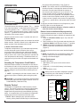
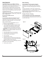
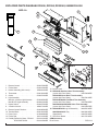
For service questions, please call Dimplex at 1-888-346-7539.
For sales inquiries, please call Sylvane at 1-800-934-9194 or visit sylvane.com.
Service Manual
Model Number:
DF2426
DF2550
DFG2562
BF9000
UL Part Number
6905050100 to 500
6907560100
IMPORTANT SAFETY INFORMATION: Always read this manual first before attempting to service this
fireplace. For your safety, always comply with all warnings and safety instructions contained in this
manual to prevent personal injury or property damage.
Dimplex North America Limited
1367 Industrial Road Cambridge ON Canada N1R 7G8
1-888-346-7539 www.dimplex.com
In keeping with our policy of continuous product development, we reserve the right to make changes without notice.
© 2011 Dimplex North America Limited
REV
PCN
DATE
00
-
22-JUL-11
01
-
26-AUG-11
02
13118
13-DEC-11
03
-
31-JAN-14
7400250000R03
TABLE OF CONTENTS
Operation. . . . . . . . . . . . . . . . . . . . . . . . . . . . . . . . . . . . . . . . . . . . . . . . . . . . . . . . . . . 3
Maintenance. . . . . . . . . . . . . . . . . . . . . . . . . . . . . . . . . . . . . . . . . . . . . . . . . . . . . . . . . 4
Exploded Parts Diagram: DF2426, DF2550, DFG2562, 6905050100-500 . . . . . . . . 5
Wiring Diagram: DF2426, DF2550, DFG2562, 6905050100-500. . . . . . . . . . . . . . . . 6
Exploded Parts Diagram - BF9000, 6907560100. . . . . . . . . . . . . . . . . . . . . . . . . . . . 7
Wiring Diagram - BF9000, 6907560100 . . . . . . . . . . . . . . . . . . . . . . . . . . . . . . . . . . . 8
Preparation for Service. . . . . . . . . . . . . . . . . . . . . . . . . . . . . . . . . . . . . . . . . . . . . . . . 9
Light Assembly Replacement . . . . . . . . . . . . . . . . . . . . . . . . . . . . . . . . . . . . . . . . . . 9
MOD 0-A . . . . . . . . . . . . . . . . . . . . . . . . . . . . . . . . . . . . . . . . . . . . . . . . . . . . . . . . . . . . . . . . . . . . . . 9
MOD B. . . . . . . . . . . . . . . . . . . . . . . . . . . . . . . . . . . . . . . . . . . . . . . . . . . . . . . . . . . . . . . . . . . . . . . 10
Flicker Motor/Flicker Rod Replacement . . . . . . . . . . . . . . . . . . . . . . . . . . . . . . . . . 10
Heater Assembly Replacement . . . . . . . . . . . . . . . . . . . . . . . . . . . . . . . . . . . . . . . . . 11
High Temperature Cutout Replacement . . . . . . . . . . . . . . . . . . . . . . . . . . . . . . . . . . 11
3-Position or Heater Switch Replacement . . . . . . . . . . . . . . . . . . . . . . . . . . . . . . . 12
Thermostat replacement. . . . . . . . . . . . . . . . . . . . . . . . . . . . . . . . . . . . . . . . . . . . . . 12
Remote Control Receiver Replacement . . . . . . . . . . . . . . . . . . . . . . . . . . . . . . . . . 12
LED Log Driver Replacement. . . . . . . . . . . . . . . . . . . . . . . . . . . . . . . . . . . . . . . . . . 13
Power Cord Replacement. . . . . . . . . . . . . . . . . . . . . . . . . . . . . . . . . . . . . . . . . . . . . 13
Assembly Part Pictures . . . . . . . . . . . . . . . . . . . . . . . . . . . . . . . . . . . . . . . . . . . . . . 14
LOWER ELECTRICAL HOUSING . . . . . . . . . . . . . . . . . . . . . . . . . . . . . . . . . . . . . . . . . . . . . . . .
UPPER PANEL TERMINAL BLOCK CONNECTIONS . . . . . . . . . . . . . . . . . . . . . . . . . . . . . . . . .
HEATER ASSEMBLY CONNECTIONS. . . . . . . . . . . . . . . . . . . . . . . . . . . . . . . . . . . . . . . . . . . . .
HEATER ASSEMBLY CONNECTIONS WITH HIGH TEMPERATURE CUTOUT. . . . . . . . . . . . .
REMOTE CONTROL RECEIVER BOARD CONNECTIONS. . . . . . . . . . . . . . . . . . . . . . . . . . . . .
THERMOSTAT DIAL, HEATER AND 3-POSITION SWITCHES. . . . . . . . . . . . . . . . . . . . . . . . . .
14
14
15
15
16
16
Troubleshooting Guide. . . . . . . . . . . . . . . . . . . . . . . . . . . . . . . . . . . . . . . . . . . . . . . 17
Always use a qualified technician or service agency to repair this fireplace.
! NOTE: Procedures and techniques that are considered important enough to emphasize.
CAUTION: Procedures and techniques which, if not carefully followed, will result in damage to the
equipment.
WARNING: Procedures and techniques which, if not carefully followed, will expose the user to the
risk of fire, serious injury, or death.
2www.dimplex.com
OPERATION
Figure 1
C
B
A
A. 3-Position Switch
The switch has two On positions marked. The “ -- “ position
is for manual operation. In this position the built-in remote
control is by-passed. The “ = “ position is for operating
the unit with the provided remote control. When in remote
control (“ = “) position the unit is operated with the On and
Off buttons of the remote control.
When the switch is in the center “o” position the unit is off.
B. Heater Switch
The Heater Switch supplies power to the heater fan and the
heater element. When the switch is in the ON position the
heater operates if the thermostat calls for heat.
C. Heater Thermostat Control
To adjust the temperature to your individual requirements,
turn the thermostat control clockwise all the way to
turn on the heater. When the room reaches the desired
temperature, turn the thermostat knob counter-clockwise
until you hear a click. Leave in this position to maintain the
room temperature at this setting. For additional heat, turn
clockwise until you hear the click again and the heater will
turn on.
Resetting the Temperature Cutoff Switch
Should the heater overheat, an automatic cut out will turn
the fireplace off and it will not come back on without being
reset. It can be reset by switching the 3-Position Switch to
Off and waiting five (5) minutes before switching the unit
back on.
! NOTE: If operating the unit with a remote control, the
remote may require re-initializing after turning the power
off.
CAUTION: If you need to continuously reset the heater,
disconnect power and call Dimplex customer service at
1-888-DIMPLEX (1-888-346-7539).
Remote Control
The fireplace is supplied with a radio frequency remote
control. This remote control has a range of approximately
50 feet (15.25 m), it does not have to be pointed at the
fireplace and can pass through most obstacles (including
walls). It is supplied with one of hundreds of independent
frequencies to prevent interference with other units.
! NOTE: Before attempting any operation with the
remote, pull the plastic insulator strip out from between
the remote casing and battery cover (Figure 2).
! NOTE: The remote control is an EEPROM system;
therefore if power is interrupted for whatever reason,
the built-in receiver board will hold the memory of
the remote’s radio frequency for up to 24 hours. The
remote should continue to operate the fireplace as
normal once unit is re-powered. Re-initialization of the
remote control to the fireplace should only be required
if there is a loss of power to the receiver for longer than
24 hours. (i.e. power failure, main power switch is turned
off).
To operate, push the ON button to turn fireplace on, push
the OFF button to turn the fireplace off.
! NOTE: Ensure that the fireplace 3-Position switch is
set to the remote control setting.
Remote Control Initialization/Reprogramming
If the hand held transmitter or receiver board has been
replaced, follow these steps to initialize the transmitter and
receiver:
1. Place the 3-Position Switch (Figure 1A) in the OFF
(“O”) position.
2. Wait a minimum of five (5) seconds and then place the
3-Position Switch in the Remote Control (“=”) position.
3. Within 10 seconds of changing the switch position,
press the ON button located on the remote control
(Figure 2).
This will synchronize the remote control and the fireplace
receiver.
! NOTE: You will have only 10 seconds to perform this
last step. Failure to do so will result in these steps
needing to be followed again.
Battery Replacement
To replace the battery:
1. Slide battery cover open on the remote control
(Figure 2).
2. Install one (1) 12-Volt (A23) battery in the battery
holder.
3. Close the battery cover
Battery must be recycled or disposed of properly.
Check with your Local Authority or Retailer for
recycling advice in your area.
Figure 2
On
Button
Off Button
Plastic
Strip
Battery
Cover
3
MAINTENANCE
Light Bulb Replacement (Mod 0-A Only)
Allow at least five (5) minutes for light bulbs to cool before
touching bulbs to avoid accidental burning of skin.
Light bulbs need to be replaced when you notice a dark
section of the flame or when the clarity and detail of the
log ember bed exterior disappears. There are two 2 bulbs
under the log set, which generate the flames and embers.
Light Bulb Requirements
Quantity of two 2 clear chandelier or candelabra bulbs with
an E-12 (small) socket base, 60 Watt rating. Example: GE
60BC or Philips 60 CTC.
Do not exceed 60 Watts per bulb.
Helpful Hints
It is a good idea to replace both light bulbs at one time
if they are close to the end of their rated life. Group
replacement will reduce the number of times you need to
open the unit to replace light bulbs. Care must be taken
when removing the log set.
To Access The Lower Light Bulb Area: (Figure 3)
1. Remove front glass assembly.
2. Pull the front edge of the plastic Ember Bed, plastic
grate or Media Tray (depending on Model) up and
forward until the rear tab releases from the ledge
located at the bottom of the partially reflective glass.
! IMPORTANT: Only handle the log set by the ember bed.
Glass Cleaning
The front glass is cleaned in the factory during the
assembly operation. During shipment, installation,
handling, etc., the front glass may collect dust particles,
these can be removed by dusting lightly with a clean dry
cloth.
To remove fingerprints or other marks, the glass can be
cleaned with a damp cloth. The glass should be completely
dried with a lint free cloth to prevent water spots. To
prevent scratching, do not use abrasive cleaners or spray
liquids on the glass surface.
Fireplace Surface Cleaning
To remove fingerprints or other marks, the exterior finish
can be cleaned with a damp cloth with a mild detergent.
The surface should be completely dried with a lint free cloth
to prevent water spots.
Figure 3
Flicker
! NOTE: Log set fits tightly into firebox, some force may
be necessary to remove.
3.
4.
5.
6.
7.
8.
Set Log Set/ Media Tray in front of fireplace.
Disconnect flicker from motor (see Figure 3).
Unscrew bulbs counter clockwise.
Insert new bulbs.
Reconnect flicker to motor.
Replace the log set by inserting the front edge of the
log set and push down on the rear edge of the ember
bed until it snaps into place (Figure 4).
! NOTE: Ensure the log set is installed tightly under the
back ledge to prevent light leakage.
9. Replace glass assembly.
Figure 4
Mirror
Ember Bed
Assembly
Back Ledge
Rear Tab
Front Edge
Side Section
4www.dimplex.com
EXPLODED PARTS DIAGRAM: DF2426, DF2550, DFG2562, 6905050100-500
MOD 0-A
9
3
5
11
14
13
1
16
16
4
7
8
15
6
10
12
Mod B
17
6
2
1.
2.
3.
4.
5.
6.
Remote Control. . . . . . . . . . . . . . . . . . . . 3000370500RP
Flicker Motor. . . . . . . . . . . . . . . . . . . . . . 2000210200RP
Heater Assembly (with cutout). . . . . . . . 2200491100RP
Thermostat . . . . . . . . . . . . . . . . . . . . . . . 2300150100RP
Cutout. . . . . . . . . . . . . . . . . . . . . . . . . . . 2300270100RP
Light Assembly
Mod 0-A: 2 Socket Light Harness. . . . . . 2500400500RP
Mod B: LED Light Assembly. . . . . . . . . . 9600810100RP
7. Heater Switch . . . . . . . . . . . . . . . . . . . . . 2800070700RP
8. 3-Position Switch. . . . . . . . . . . . . . . . . . 2800071100RP
9. Remote Control Receiver . . . . . . . . . . . . 3000380200RP
10.Terminal Block . . . . . . . . . . . . . . . . . . . . 4000150100RP
11. Power Cord . . . . . . . . . . . . . . . . . . . . . . 4100040900RP
12.Flicker Rod . . . . . . . . . . . . . . . . . . . . . . . 5901110100RP
13.Partially Reflective Glass - DF2426. . . . 5901410100RP
DF2550/DFG2562. . . . . . . . . . . 5901410200RP
14.Control Knob . . . . . . . . . . . . . . . . . . . . . 8801080100RP
15. DF2426SS Stainless Steel Trim Assembly
(comes with Front Glass) . . . . . . . . . . . . 1020230280RP
DF2426GB Gloss Black Trim Assembly
(comes with Front Glass) . . . . . . . . . . . . 1020230104RP
DF2550/DFG2562 Flat Black Trim Assembly
(comes with Front Glass) . . . . . . . . . . . . 1020230359RP
6905050400/6905050500 Silver Trim Assembly
(comes with Front Glass) . . . . . . . . . . . . 1020230478RP
16. DF2426/DF2550 Log Set Assembly. . . . 0439970100RP
6905050400/0500 Tray . . . . . . . . . . . . . 0440400100RP
Glass Media . . . . . . . . . . . . . . . . . . . . . . 1400070100RP
17. LED Driver Board. . . . . . . . . . . . . . . . . . 3001170100RP
OEM Accessory
River Rocks . . . . . . . . . . . . . . . . . . . . . . . . . . . . . . DFS1314
5
WIRING DIAGRAM: DF2426, DF2550, DFG2562, 6905050100-500
MOD 0-A
MOD B
THERMOSTAT
OFF
REMOTE
HEATER ON/OFF
MANUAL
BLOWER HEATER ASSEMBLY
FLICKER MOTOR
ON/OFF REMOTE
L
SWITCH OUPUT
N
CAPACITOR
CORD SET
LED LIGHT HARNESS
LED DRIVER BOARD
6www.dimplex.com
EXPLODED PARTS DIAGRAM - BF9000, 6907560100
MOD 0-A
17
3
9
4
5
1
14
7
13
8
16
6
15
11
10
12
2
MOD B
6
17
19
1.
2.
3.
4.
5.
6.
Remote Control. . . . . . . . . . . . . . . . . . . 3000370500RP
Flicker Motor. . . . . . . . . . . . . . . . . . . . . 2000210200RP
Heater Assembly (with cutout). . . . . . . . 2200491100RP
Thermostat . . . . . . . . . . . . . . . . . . . . . . 2300150100RP
Cutout. . . . . . . . . . . . . . . . . . . . . . . . . . 2300270100RP
Light Assembly
Mod 0-A: 2 Socket Light Harness. . . . . 2500400500RP
Mod B: LED Light Assembly. . . . . . . . . 9600810100RP
7. Heater Switch . . . . . . . . . . . . . . . . . . . . 2800070700RP
8. 3-Position Switch. . . . . . . . . . . . . . . . . . 2800071100RP
9. Remote Control Receiver . . . . . . . . . . . 3000380200RP
10.Terminal Block. . . . . . . . . . . . . . . . . . . . 4000150100RP
11. Power Cord. . . . . . . . . . . . . . . . . . . . . . 4100040300RP
12.Flicker Rod . . . . . . . . . . . . . . . . . . . . . . 5901110100RP
13.Partially Reflective Glass . . . . . . . . . . . 5901410100RP
14.Control Knob. . . . . . . . . . . . . . . . . . . . . 8801080100RP
15.30” Trim Assembly with Front Glass. . . 6907580100RP
16.LED Logset Assembly Mod 0-A. . . . . . . 0440590100RP
Mod B. . . . . . . . 0440590300RP
17.LED Driver Mod 0-A . . . . . . . . . . . . . . . 3000390100RP
Mod B. . . . . . . . . . . . . 3001170100RP
18.LED Wire Harness. . . . . . . . . . . . . . . . . 2500380300RP
19.LED Log Driver Board (Mod B only). . . 3001220100RP
7
WIRING DIAGRAM - BF9000, 6907560100
MOD 0-A
OFF
HEATER ON/OFF
MANUAL
THERMOSTAT
REMOTE
BLOWER HEATER ASSEMBLY
FLICKER MOTOR
ON/OFF REMOTE
SWITCH OUPUT
CORD SET
CAPACITOR
LIGHT HARNESS ASSEMBLY
MOD B
THERMOSTAT
FLICKER MOTOR
MANUAL
OFF
HEATER ON/OFF
REMOTE
BLOWER HEATER ASSEMBLY
ON/OFF REMOTE
L
SWITCH OUPUT
N
LOG SET ASSEMBLY
CORD SET
CAPACITOR
LED LIGHT HARNESS ASSEMBLY
8www.dimplex.com
PREPARATION FOR SERVICE
CAUTION: If unit was operating prior to servicing allow
at least 10 minutes for lights, heating elements and top
panel to cool off to avoid accidental burning of skin.
1. Remove the firebox out of the cabinet or wall frame that
surrounds the unit.
2. Disconnect power before attempting any maintenance.
! NOTE: This unit may have been installed to a power
source in one of 2 ways: (SEE FIGURE 5 & 6).
• Option #1 – Plugged into an outlet.
A power cord with plug, inserted into an outlet near
or behind the fireplace, unplug the fireplace from the
outlet.
• Option #2 – Hardwire connection.
Power supplied from electrical wire coming from a
dedicated, properly fused circuit with 120 Volt, 15 Amp
rating directly from the main electrical panel, turn the
breaker off at the electrical panel.
• It is recommended during original installation,
there should be an allowance of up to 8 feet of
service cable for connecting power supply to the
junction box on fireplace.
3. Remove the front glass assembly by lifting the front
glass assembly off of the 4 mounts located on the outer
casing of the fireplace 2 on the left and 2 on the right.
Carefully place the glass assembly aside in a safe location.
Figure 5
Figure 6
LIGHT ASSEMBLY REPLACEMENT
MOD 0-A
Tools required: Phillips head screw driver
Small wire cutter
CAUTION: Follow “Preparation for Service” instructions
before proceeding.
1. Slightly wedge your fingers between the partially reflective glass and the log-set/ember-bed on either the right
or left side. Pull the back edge of the plastic ember
bed forward until the rear tab/ledge clears past the bottom of the partially reflective glass and pull the log set
forward and out of the unit. (Figure 4).
! IMPORTANT: Only handle the log-set by the plastic
ember-bed, not the logs themselves.
! NOTE: Log-set fits tightly into firebox. Some force
may be necessary to remove.
! NOTE: If your model has the media tray with the
decorative glass pieces as an ember bed, remove the glass
pieces then remove the plastic media tray following the
same method as the log set removal instructions.
2. Set log-set or media bed aside in a safe location.
3. Disconnect the flicker rod from the motor by pulling and
twisting the rubber gasket/connector away from the
motor. This is the gasket which joins the rod and the
motor together. Once separated, pull the flicker rod out
from the bracket and bushing from opposite side, and
remove it from the firebox.
! NOTE: Be careful not to bend the rod. Doing so may
damage the rod. Ensure the rod is straight after re-installation so that it doesn’t affect the operation of the flicker
effect.
4. Carefully turn the firebox upside down so that the bottom panel is facing up.
5. Remove the 9 screws that hold the bottom panel in
place, 2 on the back, 2 on the left, 2 on the right and 3
on the bottom along the front edge.
6. Remove the light bulbs by turning counter clockwise.
7. Remove the rings that hold the sockets to the side
panel by turning/unscrewing the rings counter clockwise. Push the sockets out of the panel.
8. Cut the wire ties that are holding the wires to the casing.
9. Remove the light harness wire ends out of the terminal
block by removing the small Philips head screw in the 2
respective terminals.
10. Insert the wire ends from the new light harness into
the terminal block following the same orientation of the
original harness.
11. Tighten terminal screws to secure wires in place.
12. Insert the new sockets into the opening on the socket
panel on the left and right. Place the ring onto the
socket and tighten to secure the socket into place.
13. Tuck the light harness wires around the light panel/cas9
ing so that they will not be pinched when re-attaching
the bottom panel.
14. Insert new bulbs.
15. Re-assemble the firebox in reverse order.
! NOTE: Ensure the rear tab/ledge on the log-set/emberbed is installed tightly under the bottom of the partially
reflective glass to prevent light leakage.
MOD B
Tools required: Phillips head screw driver
Small wire cutter
CAUTION: Follow “Preparation for Service” instructions
before proceeding.
1. Carefully turn the firebox onto its back so that the bottom can be easily accessed.
2. Remove the 9 screws that attach the bottom panel to
the side panels, 2 on the back side, 2 on the left side,
2 on the right side and 3 on the bottom along the front
edge. (Figure 7)
3. Locate the LED light assembly and remove the 4
screws securing the assembly to the two side panels.
4. Remove the light assembly wire ends out of the terminal block by removing the small Philips head screw in
the 2 respective terminals.
5. Insert the wire ends from the new light assembly into
the terminal block following the same orientation of the
original wires.
6. Install the new LED light assembly back into the unit.
7. Re-assemble the firebox in reverse order.
! NOTE: Ensure that when reinstalling the bottom panel
of the firebox that no wires are pinched.
Figure 7
LED Light
Assembly
Terminal Block
FLICKER MOTOR/FLICKER ROD
REPLACEMENT
Tools Required: Phillips head screw driver
CAUTION: Follow “Preparation for Service” instructions
before proceeding.
1. Slightly wedge your fingers between the back partially
reflective glass and the log-set/ember-bed on either
the right or left side. Pull the back edge of the plastic
ember bed forward until the rear tab/ledge clears past
the bottom of the partially reflective glass and pull the
log set forward and out.
! IMPORTANT: Only handle the log-set by the plastic
ember-bed, not the logs themselves.
! NOTE: Log-set fits tightly into firebox. Some force
may be necessary to remove.
! NOTE: If your model has the media tray with the
decorative glass pieces as an ember bed, remove the glass
pieces then remove the plastic media tray following the
same method as the log set removal instructions.
2. Set log set or media tray aside in a safe location.
3. Disconnect flicker rod from the motor by slightly bending the flicker rod and pulling the rubber gasket off the
motor shaft. (Figure 3).
! NOTE: Be careful not to bend the rod. Doing so may
damage the rod. Ensure the rod is straight after re-installation so that it doesn’t affect the operation of the flicker
effect.
4. Carefully turn the firebox upside down so that the bottom panel is facing up.
5. Remove the 9 screws that attach the bottom panel to
the side panels, 2 on the back side, 2 on the left side,
2 on the right side and 3 on the bottom along the front
edge.
6. Remove the 3 flicker motor wire ends out of the terminal block by removing the small Philips head screw in
the 3 respective terminals. Take note of their location
on the terminal block.
! NOTE: A capacitor is also connected in 2 of the 3
terminals that hold the flicker motor wires on the terminal
block. Take note of the terminal locations and the wire
configuration.
7. Using a Philips screwdriver (a short screwdriver is
recommended), remove the 2 screws holding the flicker
motor to the mounting brackets. One screw on either
side and remove the flicker motor out of the housing.
Take note of the orientation on the brackets.
8. Place the new motor into the housing and attach the
motor to the brackets using the 2 Philips screws.
9. Insert the 3 wire ends from the new flicker motor as
well as the 2 wires from the original capacitor into the
terminal block following the orientation of the original
motor & capacitor. (See Assembly Part Pictures)
10. Tighten terminal screws to secure wires in place.
10www.dimplex.com
11. Re-assemble the firebox in reverse order.
! NOTE: Ensure the rear tab/ledge on the log-set/ember-bed is installed tightly under the bottom of the partially
reflective glass to prevent light leakage.
HEATER ASSEMBLY REPLACEMENT
Tools Required: Philips head screwdriver
Needle nose pliers
CAUTION: Follow “Preparation for Service” instructions
before proceeding.
1. Remove 9 screws that secure the top panel to the side
panels of the firebox using a Philips head screwdriver,
2 on the left side; 2 on the right side; 3 on the backside;
2 on the top.
2. Lift the top off the firebox. Turning the panel 45 degrees, rest it inside the cavity at the top to provide you
with some support and leverage while following Steps
4 & 5.
3. Noting their original location, disconnect the wires attached to the end of the heater assembly on the blower
motor and element. Using a flat head screwdriver gently pry between the end of the connector and the heater
to release the wires
! NOTE: Some of the wires may have a “piggy-back”
connector that allows a second wire to connect to the same
prong as the first wire. Keep the “piggy-back” connection
together when pulling the wires off the heater assembly.
! NOTE: In some cases the wire running from the
cutout will not reach the terminal block where the previous
wire was removed from, see Figure 8. The new wire is
provided with an insert connection, slide the plastic cover
up and bend the connection in half. Remove the wire on
the blower motor, that is running from the same spot off of
the terminal block, install the new bent wire, then install the
previously removed wire onto the bent connection.
4. Remove the 2 mounting brackets that attach the heater
assembly to the top panel. Ensure that the heater assembly is supported when removing the brackets.
5. Remove the mounting brackets from the heater assembly by removing the 2 Philips screws from each
bracket.
6. Attach the brackets to the new heater assembly and
then attach brackets to the top panel.
7. Re-assemble in reverse order as above.
HIGH TEMPERATURE CUTOUT
REPLACEMENT
Tools Required: Philips head screwdriver
Needle nose pliers
CAUTION: Follow “Preparation for Service” instructions
before proceeding.
1. Remove 9 screws that secure the top panel to the side
panels of the firebox using a Philips head screwdriver,
2 on the left side; 2 on the right side; 3 on the backside;
2 on the top.
2. Lift the top off the firebox. Turning the panel 45 degrees, rest it inside the cavity in the top to provide you
with some support and leverage while following Step 4.
CAUTION: Support the back underside of the firebox
with a small piece of wood as the feet do not go the entire
depth of the unit and it can easily tip backwards.
3. Remove the 2 mounting brackets that attach to the
heater assembly to the top panel. Ensure that the heater assembly is supported when removing the brackets.
4. Locate the High Temperature Cutout found on the outer
casing of the heater assembly at the elements.
5. Follow the wires to the terminal block and disconnect
the 2 wires at the terminal block.
6. Using a small diameter, Philips screwdriver, remove the
old cutout and replace it with the new one following the
orientation of the original wires. (See Assembly Part
Pictures)
! NOTE: In some cases the wire running from the
cutout will not reach the terminal block where the previous
wire was removed from, see Figure 8. The new wire is
Figure 8
Original Wiring
SHORT CONNECTION
TERMINAL BLOCK
BLOWER HEATER ASSEMBLY
New Wiring
ENSURE WIRE IS ROUTED AROUND BLOWER
TERMINAL BLOCK
BLOWER HEATER ASSEMBLY
BEND
HERE
11
provided with an insert connection, slide the plastic cover
up and bend the connection in half. Remove the wire on
the blower motor, that is running from the same spot off of
the terminal block, install the new bent wire, then install the
previously removed wire onto the bent connection.
7. Re-assemble in reverse order as described above.
3-POSITION OR HEATER SWITCH
REPLACEMENT
Tools Required: Philips head screwdriver
Needle nose pliers
CAUTION: Follow “Preparation for Service” instructions
before proceeding.
1. Remove 9 screws that secure the top panel to the side
panels of the firebox using a Philips head screwdriver,
2 on the left side; 2 on the right side; 3 on the backside;
2 on the top.
2. Lift the top panel up off the firebox, turn it 45 degrees
and rest it inside the upper cavity against the back
panel.
CAUTION: Support the back underside of the firebox
with a small piece of wood as the feet do not go the entire
depth of the unit and it can easily tip backwards.
3. The switch housing panel spans across the front of the
fireplace, near the top. Remove the 6 screws from the
side panels that hold this front panel in place, 3 on the
left and 3 on the right side.
4. Lift the switch-housing panel up and flip it 180 degrees
towards you to expose the wires connected to the
backside of the switch.
5. Taking note of the original location of each wire connected to the switch that needs replacing, (either the
3-Position or the Heater Switch) remove the wires.
! NOTE: Using a flat head screwdriver gently pry between the end of the connector and the switch to release
the wires.
6. Noting the orientation of the switches - the markings
on the face, depress the tabs that secure the switch to
the housing from behind the panel and push the switch
out to the front. Using needle nosed pliers will give you
a better grip and fit to depress both these tabs at the
same time.
7. Push the new switch in place, ensuring that both tabs
are engaged.
8. Re-assemble in reverse order as described above.
THERMOSTAT REPLACEMENT
Tools Required: Philips head screwdriver
CAUTION: Follow “Preparation for Service” instructions
before proceeding.
1. Remove 9 screws that secure the top panel to the side
panels of the firebox using a Philips head screwdriver,
2 on the left side; 2 on the right side; 3 on the backside;
2 on the top.
2. Lift the top panel up off the firebox, turn it 45 degrees
and rest it inside the upper cavity against the back
panel.
CAUTION: Support the back underside of the firebox
with a small piece of wood as the feet do not go the entire
depth of the unit and it can easily tip backwards.
3. On the front face of the switch housing, remove the 2
screws that hold the thermostat to the panel.
4. The switch housing panel spans across the entire top
on the front of the fireplace. Remove the 6 screws
from the side panels that hold this front panel in place,
3 on the left and 3 on the right side.
5. Lift the switch-housing panel up and flip it 180 degrees
towards you to expose the wires connected to the
backside of the thermostat.
6. Remove the dial off the control shaft by pulling forward
away from the thermostat.
! NOTE: Note that the dial will only go back on the shaft
one way when replacing.
7. Remove thermostat from the mounting bracket by removing the 2 Philips screws located on the bracket.
8. Taking note of the original location of each wire connected to the thermostat remove the wires and place
onto the new thermostat.
! NOTE: Using a flat head screwdriver gently pry
between the end of the connector and the thermostat to
release the wires.
9. Re-assemble in reverse order as described above.
REMOTE CONTROL RECEIVER
REPLACEMENT
Tools Required: Philips head screwdriver
Needle nose pliers
Small cutter or snips
CAUTION: Follow “Preparation for Service” instructions
before proceeding.
1. Remove 9 screws that secure the top panel to the side
panels of the firebox using a Philips head screwdriver,
2 on the left side; 2 on the right side; 3 on the backside;
2 on the top.
2. Lift the top panel up off the firebox, turn it 45 degrees
and rest it inside the upper cavity against the back
panel.
CAUTION: Support the back underside of the firebox
with a small piece of wood as the feet do not go the entire
depth of the unit and it can easily tip backwards.
3. The switch housing panel spans across the entire top
on the front of the fireplace. Remove the 6 screws
from the side panels that hold this front panel in place,
3 on the left and 3 on the right side.
4. Lift up the switch-housing panel and carefully rest it
inside the upper cavity.
5. Taking note of the original location of each wire connected to the board, remove each wire and connect
12www.dimplex.com
them onto the same location on the new receiver
board.
! NOTE: Using a flat head screwdriver gently pry
between the end of the connector and the circuit board to
release the wires.
6. Remove the old board off the plastic mounts, by
squeezing the tab inward and sliding the board off.
7. Replace any plastic mounts that may have broken by
pushing the old mounts out towards the back. Replace
the new mounts from the back.
8. Line up the holes on the corners of the new remote
control receiver board and press the new board onto
the mounts. Make sure the board is secure.
9. Re-assemble in reverse order as described above.
2.
3.
4.
5.
6.
the 2 Philips screws mounted to the back panel of the
fireplace.
Unscrew the 2 wire connectors that join the power cord
at the bottom to the wire leads coming down from the
top.
With a pair of needle nose pliers, open the strain relief
bushing that holds the power cord in place on the junction box cover and remove the cord.
Feed the new power cord through the junction box and
squeeze the new strain relief in place on the cord and
junction box.
Re-connect wires. –(Wide blade on the plug is the neutral side of the power cord).
Re-assemble in the reverse order as above.
LED LOG DRIVER REPLACEMENT
Tools Required: Philips head screwdriver
Needle nose pliers
Small cutter or snips
CAUTION: Follow “Preparation for Service” instructions
before proceeding.
1. Remove 9 screws that secure the top panel to the side
panels of the firebox using a Philips head screwdriver,
2 on the left side; 2 on the right side; 3 on the backside;
2 on the top.
2. Lift the top panel up off the firebox, turn it 45 degrees
and rest it inside the upper cavity against the back
panel.
CAUTION: Support the back underside of the firebox
with a small piece of wood as the feet do not go the entire
depth of the unit and it can easily tip backwards.
3. Taking note of the original location of each wire connected to the board, remove each wire and connect
then onto the same location on the new log driver
board.
! NOTE: Using a flat head screwdriver gently pry
between the end of the connector and the circuit board to
release the wires.
4. Remove the old board off the plastic mounts, by
squeezing the tab inward and sliding the board off.
5. Replace any plastic mounts that may have broken by
pushing the old mounts out towards the top. Replace
the new mounts from the back.
6. Line up the holes on the corners of the new log driver
board and press the new board onto the mounts. Make
sure the board is secure.
7. Re-assemble in reverse order as described above.
POWER CORD REPLACEMENT
Tools required: Phillips head screw driver.
Needle nosed pliers.
CAUTION: Follow “Preparation for Service” instructions
before proceeding. Steps 1 & 2 only.
1. Remove power cord junction box cover by removing
13
ASSEMBLY PART PICTURES
LOWER ELECTRICAL HOUSING
VIEW FROM THE BOTTOM
Flicker Motor
Lower Terminal Block
Flicker Motor Connection White (with capacitor wire)
Capacitor - Connects to the terminals with the brown and white
wires from the flicker motor
Flicker Motor Connection White (with capacitor wire)
Flicker Motor Connection
- Black Single
Light Harness Connection
- Neutral
Light Harness Connection
- Live
Power Cord or Hardwire
Internal Connection
Light Socket
UPPER PANEL TERMINAL BLOCK CONNECTIONS
White - Connects to a piggy back
connection on JP3 prong on
circuit board
Long white connects to
lower electrical housing
Red - Connects to the Inside/
middle prong on heat on/off
switch
White - “Piggy-backed” to
white jumper from bottom
prong on the element
Red - From High Temperature
Cutout
Grey - From High Temperature
Cutout
Grey - Connects to the Thermostat
Grey - To Blower motor outside
prong.
14www.dimplex.com
HEATER ASSEMBLY CONNECTIONS
Blower
Connects to Terminal
Block
White - Connects to
Terminal Block
White - Jumper to
Blower Motor
Jumper to “Piggy Back”
connection on lower
prong of element
Yellow - Connects to
Thermostat
Grey - Connects to High
Temperature Cutout on
Terminal Block
Red - From the high
temperature cutout to
the terminal block.
HEATER ASSEMBLY CONNECTIONS WITH HIGH TEMPERATURE CUTOUT
View of Heater Assembly removed from the top panel
High Temperature Cutout
Element Housing
Blower Housing
Blower Motor
Upper Panel Terminal
Block
15
REMOTE CONTROL RECEIVER BOARD CONNECTIONS
VIEW FROM THE TOP RIGHT SIDE
Stand-Off Clips (4) - Attaching
receiver board to housing
Switch Output (Black) to outside
prong of 3-Position Switch
JP1 - Connects to inside
prong of 3-Position Switch
Switch Output (Black “Piggy
Back”) to “Piggy Back” Connection on Outside Prong on
Heater On/Off Switch
JP3 (White) from upper
terminal block
JP3 (White “Piggy Back”)
from lower electrical housing
THERMOSTAT DIAL, HEATER AND 3-POSITION SWITCHES
EXTERIOR VIEW OF SWITCH PANEL
Heater Switch
O - Off
-- On
Thermostat Dial
3-Position Switch
= Remote Control
O Off
-- Manual Control
THERMOSTAT DIAL, HEATER AND 3-POSITION SWITCHES
INTERIOR VIEW – BACK SIDE OF SWITCH PANEL
Outside Prong (Black) connects to
Switch Output (Black “Piggy back”)
on Receiver Board
Middle Prong (Black) connects to
Black from lower electrical housing
Inside Prong (Red) connects to JP1
on Receiver Board
Yellow from Heating
Element
Grey from Upper
Panel Terminal Block
• Outside Prong (Black) connects to
Lower Electrical Housing
• Outside Prong (Black - “Piggy Back”)
to Switch Output on Receiver Board
Inside Prong (Red) connects
to Upper Terminal Block
16www.dimplex.com
TROUBLESHOOTING GUIDE
PROBLEM
CAUSE
SOLUTION
General
Circuit breaker trips or fuse
blows when unit is turned on
Short in unit wiring.
Trace wiring in unit.
Improper circuit current rating
Additional appliances may exceed the current rating
of the circuit breaker or fuse. Plug unit into another
outlet or install unit on a dedicated 15 amp circuit.
Unit turns on or off by itself
Remote Control has a similar frequency
to other remotes in the area.
Replace Remote Control. Initialize to Remote Control
Receiver
Radio frequency disturbance from outside sources.
Replace Remote Control and Remote Control Receiver where necessary. Initialize Remote Control and
Receiver
Defective Remote Control Receiver
Replace Remote Control Receiver. Initialize Remote
Control and Receiver.
Lights dim in room while the unit
is on
Unit is drawing close to circuit current
rating
Move the unit to another outlet or install unit on a dedicated 15 amp circuit
Power cord gets warm
Normal Operation
The power cord may get slightly warm to the touch
when the heater is on
Defective Power Cord
Replace Power Cord if cord gets hot to the touch.
Appearance
Fireplace does not turn on Manu- Improper operation
ally
No incoming power from the electrical
wall socket
Fireplace does not turn on with
the Remote Control
Refer to Operation Section
Check fuse/breaker panel
Defective 3-Position Switch
Replace 3-Position Switch
Defective Remote Control Receiver
Replace Remote Control Receiver. Initialize Remote
Control and Receiver
Improper operation
Refer to Operation Section
Remote Control not initialized to fireplace Initialize the Remote Control
Remote Control not working
Install new battery into the Remote Control. Initialize
Remote Control.
Replace Remote Control or Remote Control Receiver
where necessary. Initialize Remote Control and
Receiver.
Flame Frozen
Flame not bright or flame not
visible
Log set dim, not glowing
(BF9000 only)
Loose wiring
Check wiring connections
Defective Flicker Motor
Replace Flicker Motor
Loose wiring
Check wiring connections
Burnt out light bulbs
Replace light bulbs
Loose wiring
Check wiring connections
Defective Light Harness/ LED Light Assembly
Replace Light Harness/ LED Light Assembly
Loose wiring
Check wiring connections
Defective LED Log Driver Board
Replace LED Log Driver Board
Defective Log Set Assembly
Replace Log Set Assembly
Flame Shutter
Defective Flicker Motor
Replace Flicker Motor
Light leaking around the log set
Log set not positioned properly
Check log set for proper fit
17
PROBLEM
CAUSE
SOLUTION
Heater
Heater is not turning off
Heater is not turning on
Heater is turning off after a
couple of minutes of operation
Heater emits an odor
Heater fan turns on but heater
lacks heat
Heating element is glowing red
Heater fan runs continuously
Improper operation
Refer to Operation Section
Defective Heater Switch
Replace Heater Switch
Defective Thermostat
Replace Thermostat
Defective Remote Control Receiver
Replace Remote Control Receiver
Improper operation
Refer to Operation Section
Loose Wiring
Trace wiring in unit
Defective Heater Switch
Replace Heater Switch
Defective Thermostat
Replace Thermostat
Defective Heater Assembly
Replace Heater Assembly
Build up of dirt/dust in Heater Assembly
Ensure that exterior intake louvers and firebox cavity
are free of dirt/dust.
Defective Heater Assembly
Replace Heater Assembly
Normal Operation
Normal operation is when the heater emits an odor
for a brief period after the heater is initially turned on.
The heater is burning off any dust accumulated during
manufacturing or operation.
Defective Heater Assembly
Replace Heater Assembly
Improper operation
Refer to Operation Section
Loose wiring
Trace wiring in unit
Defective Thermostat
Replace Thermostat
Defective Heater Assembly
Replace Heater Assembly
Normal Operation
Small glowing sections of the element are considered
normal.
Defective Heater Assembly
If larger glowing sections are causing the heater to trip
the thermal cutout, unplug unit, discontinue use and
replace Heater Assembly.
Defective Heater Switch
Replace Heater Switch
Defective Thermostat
Replace Thermostat
Defective Heater Assembly
Replace Heater Assembly
Dirty Heater Assembly
Ensure that exterior intake louvers and firebox cavity
are free of dirt/dust.
Defective Heater Assembly
Replace Heater Assembly
Flicker Rod hitting or rubbing against
internal components
Ensure rod is straight and mounted properly in the
bracket, spinning freely away from other components.
Replace if necessary.
Defective Flicker Motor
Replace Flicker Motor
Noise
Excessive noise with the heater
on
Grinding or excessive noise with
the heater off
18www.dimplex.com