1
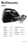
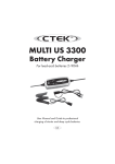
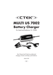
SCI90 English .............Page 02 0099001264-02 ENGLISH Model: SCI90 Automatic Battery Charger with Engine Start OWNER’S MANUAL 1. Read manual before using product. Do not expose to rain or snow. Protect your eyes. 1HYHUVPRNHRUDOORZÀDPHV and sparks. Wear protective clothing. Keep out of reach of children Risk of explosive gases. Disconnect the mains cable before connecting or disconnecting the clamps. Risk of electric shock. Use in a well-ventilated area. IMPORTANT SAFETY INSTRUCTIONS – SAVE THESE INSTRUCTIONS. This manual will show you how to use your charger safely and effectively. Please read, understand and follow these instructions and precautions carefully, as this manual contains important safety and operating instructions. The safety messages used throughout this manual contain a signal word, a message and an icon. The signal word indicates the level of the hazard in a situation. Indicates an imminently hazardous situation which, if not avoided, will result in DANGER death or serious injury to the operator or bystanders. Indicates a potentially hazardous situation which, if not avoided, could result in WARNING death or serious injury to the operator or bystanders. IMPORTANT Indicates a potentially hazardous situation which, if not avoided, could result in damage to the equipment or vehicle or property damage. WARNING RISK OF ELECTRIC SHOCK OR FIRE. 1.1 To reduce the risk of damage to the electric plug or cord, pull by the plug rather than the cord when disconnecting the charger. 1.2 This charger is not intended for use by children. Persons with reduced physical, sensory or mental capabilities, or lack of experience and knowledge, must be given supervision or instruction concerning the use of the product by a person responsible for their safety. 1.3 Children should be supervised to ensure they do not play with the charger. 1.4 An extension cord should not be used unless absolutely necessary. Use of an improper H[WHQVLRQFRUGFRXOGUHVXOWLQDULVNRI¿UHDQGHOHFWULFVKRFN,IDQH[WHQVLRQFRUGPXVWEH used, make sure: That the pins on the plug of the extension cord are the same number, size and shape as those of the plug on the charger. That the extension cord is properly wired and in good electrical condition. 7KDWWKHZLUHVL]HLVODUJHHQRXJKIRUWKH$&DPSHUHUDWLQJRIWKHFKDUJHUDVVSHFL¿HGLQ section 7.3. 1.5 Do not operate the charger with a damaged cord or plug; have the cord or plug replaced LPPHGLDWHO\E\DTXDOL¿HGVHUYLFHSHUVRQ 2 1.6 Do not operate the charger if it has received a sharp blow, been dropped or otherwise GDPDJHGLQDQ\ZD\WDNHLWWRDTXDOL¿HGVHUYLFHSHUVRQ 1.7 'RQRWGLVDVVHPEOHWKHFKDUJHUWDNHLWWRDTXDOL¿HGVHUYLFHSHUVRQZKHQVHUYLFHRUUHSDLU LVUHTXLUHG,QFRUUHFWUHDVVHPEO\PD\UHVXOWLQDULVNRI¿UHRUHOHFWULFVKRFN WARNING RISK OF EXPLOSIVE GASES. 1.8 WORKING IN THE VICINITY OF A LEAD-ACID BATTERY IS DANGEROUS. BATTERIES GENERATE EXPLOSIVE GASES DURING NORMAL BATTERY OPERATION. FOR THIS REASON, IT IS OF UTMOST IMPORTANCE THAT YOU FOLLOW THE INSTRUCTIONS EACH TIME YOU USE THE CHARGER. 1.9 To reduce the risk of a battery explosion, follow these instructions and those published by the battery manufacturer and the manufacturer of any equipment you intend to use in the vicinity of the battery. Review the cautionary markings on these products and on the engine. 2. PERSONAL PRECAUTIONS WARNING RISK OF EXPLOSIVE GASES. 2.1 Remove personal metal items such as rings, bracelets, necklaces and watches when working with a lead-acid battery. A lead-acid battery can produce a short-circuit current high enough to weld a ring or the like to metal, causing a severe burn. 2.2 Be extra cautious, to reduce the risk of dropping a metal tool onto the battery. It might spark or short-circuit the battery or other electrical part that may cause an explosion. 2.3 Use this charger for charging LEAD-ACID batteries only. It is not intended to supply power to a low voltage electrical system. Do not use this battery charger for charging dry-cell batteries that are commonly used with home appliances. These batteries may burst and cause injury to persons and damage to property. 2.4 NEVER charge a frozen battery. 2.5 Consider having someone nearby to come to your aid when you work near a lead-acid battery. Have plenty of fresh water and soap nearby in case battery acid contacts your skin, clothing or eyes. 2.6 If battery acid contacts your skin or clothing, immediately wash the area with soap and ZDWHU,IDFLGHQWHUV\RXUH\HLPPHGLDWHO\ÀRRGWKHH\HZLWKFROGUXQQLQJZDWHUIRUDWOHDVW 10 minutes and get medical attention right away. If battery acid is accidentally swallowed, drink milk, the whites of eggs or water. DO NOT induce vomiting. Seek medical attention immediately. 3. 3.1 3.2 3.3 3.4 3.5 3.6 3.7 3.8 PREPARING TO CHARGE WARNING RISK OF CONTACT WITH BATTERY ACID. BATTERY ACID IS A HIGHLY CORROSIVE SULFURIC ACID. Remove all cord wraps and uncoil the cables prior to using the battery charger. If it is necessary to remove the battery from the vehicle to charge it, always remove WKHJURXQGHGWHUPLQDO¿UVW0DNHVXUHDOORIWKHDFFHVVRULHVLQWKHYHKLFOHDUHRIIWR prevent arcing. Clean the battery terminals before charging the battery. During cleaning, keep airborne corrosion from coming into contact with your eyes, nose and mouth. Use baking soda and water to neutralize the battery acid and help eliminate airborne corrosion. Do not touch your eyes, nose or mouth. $GGGLVWLOOHGZDWHUWRHDFKFHOOXQWLOWKHEDWWHU\DFLGUHDFKHVWKHOHYHOVSHFL¿HGE\WKHEDWWHU\ PDQXIDFWXUHU'RQRWRYHU¿OO)RUDEDWWHU\ZLWKRXWUHPRYDEOHFHOOFDSVVXFKDVYDOYHUHJXODWHG lead-acid batteries (VRLA), carefully follow the manufacturer’s recharging instructions. Read, understand and follow all instructions for the charger, battery, vehicle and any equipment used near the battery and charger. Study all of the battery manufacturer’s VSHFL¿FSUHFDXWLRQVZKLOHFKDUJLQJDQGUHFRPPHQGHGUDWHVRIFKDUJH Determine the voltage of the battery by referring to the vehicle owner’s manual. This charger is equipped with Auto Voltage Detection of 6 or 12 volts. Make sure that the charger cable clips make tight connections. Included with your charger are two cord wrap cleats for storage of the clip cables. To install, align the two tabs with the two receptacles on the back of the charger and push until you hear a snap. 3 4. CHARGER LOCATION WARNING RISK OF EXPLOSION AND CONTACT WITH BATTERY ACID. 4.1 Locate the charger as far away from the battery as the DC cables permit. 4.2 Never place the charger directly above the battery being charged; gases from the battery will corrode and damage the charger. 4.3 Do not set the battery on top of the charger. 4.4 1HYHUDOORZEDWWHU\DFLGWRGULSRQWRWKHFKDUJHUZKHQUHDGLQJWKHHOHFWURO\WHVSHFL¿F JUDYLW\RU¿OOLQJWKHEDWWHU\ 5. 5.1 5.2 5.3 5.4 5.5 5.6 5.7 5.8 6. 6.1 6.2 6.3 6.4 6.5 6.6 6.7 6.8 FOLLOW THESE STEPS WHEN BATTERY IS INSTALLED IN VEHICLE WARNING A SPARK NEAR THE BATTERY MAY CAUSE A BATTERY EXPLOSION. TO REDUCE THE RISK OF A SPARK NEAR THE BATTERY: Position the AC and DC cables to reduce the risk of damage by the hood, door and moving or hot engine parts. NOTE: If it is necessary to close the hood during the charging process, ensure that the hood does not touch the metal part of the battery clips or cut the insulation of the cables. Stay clear of fan blades, belts, pulleys and other parts that can cause injury. Check the polarity of the battery posts. The POSITIVE (POS, P, +) battery post usually has a larger diameter than the NEGATIVE (NEG, N, -) post. Determine which post of the battery is grounded (connected) to the chassis. For a negative-grounded vehicle, connect the POSITIVE (RED) clip from the battery charger to the POSITIVE (POS, P, +) ungrounded post of the battery. Connect the NEGATIVE (BLACK) clip to the vehicle chassis or engine block away from the battery. Do not connect the clip to the carburetor, fuel lines or sheet-metal body parts. Connect to a heavy gauge metal part of the frame or engine block. For a positive-grounded vehicle, connect the NEGATIVE (BLACK) clip from the battery charger to the NEGATIVE (NEG, N, -) ungrounded post of the battery. Connect the POSITIVE (RED) clip to the vehicle chassis or engine block away from the battery. Do not connect the clip to the carburetor, fuel lines or sheet-metal body parts. Connect to a heavy gauge metal part of the frame or engine block. Connect charger AC supply cord to electrical outlet. When disconnecting the charger, disconnect the AC cord, remove the clip from the vehicle chassis and then remove the clip from the battery terminal. FOLLOW THESE STEPS WHEN BATTERY IS OUTSIDE VEHICLE WARNING A SPARK NEAR THE BATTERY MAY CAUSE A BATTERY EXPLOSION. TO REDUCE THE RISK OF A SPARK NEAR THE BATTERY: Check the polarity of the battery posts. The POSITIVE (POS, P, +) battery post usually has a larger diameter than the NEGATIVE (NEG, N, -) post. Attach at least a 24-inch (61 cm) long 6-gauge (AWG) insulated battery cable to the NEGATIVE (NEG, N, -) battery post. Connect the POSITIVE (RED) charger clip to the POSITIVE (POS, P, +) post of the battery. Position yourself and the free end of the cable you previously attached to the NEGATIVE (NEG, N, -) battery post as far away from the battery as possible – then connect the NEGATIVE (BLACK) charger clip to the free end of the cable. 'RQRWIDFHWKHEDWWHU\ZKHQPDNLQJWKH¿QDOFRQQHFWLRQ Connect charger AC supply cord to electrical outlet. When disconnecting the charger, always do so in the reverse order of the connecting SURFHGXUHDQGEUHDNWKH¿UVWFRQQHFWLRQZKLOHDVIDUDZD\IURPWKHEDWWHU\DVSUDFWLFDO A marine (boat) battery must be removed and charged on shore. To charge it onboard requires equipment specially designed for marine use. 4 7. GROUNDING AND AC POWER CORD CONNECTIONS WARNING RISK OF ELECTRIC SHOCK OR FIRE. 7.1 This battery charger is for use on a nominal 230V, 50 Hz circuit. (See the warning label on the charger for the correct input voltage.) The plug must be plugged into an outlet that is properly installed and grounded in accordance with all local codes and ordinances. The SOXJSLQVPXVW¿WWKHUHFHSWDFOHRXWOHW'RQRWXVHZLWKDQXQJURXQGHGV\VWHP DANGER 1HYHUDOWHUWKH$&FRUGRUSOXJSURYLGHG±LILWGRHVQRW¿WWKHRXWOHWKDYH DSURSHUJURXQGHGRXWOHWLQVWDOOHGE\DTXDOL¿HGHOHFWULFLDQ$QLPSURSHUFRQQHFWLRQFDQ result in a risk of an electric shock or electrocution. 7.3 Recommended minimum AWG size for extension cord: 100 feet (30.5 meters) long or less – use a 16 gauge (1.31 mm2) extension cord. Over 100 feet (30.5 meters) long – use a 14 gauge (2.08 mm2) extension cord. 7.2 8. CONTROL PANEL 1 3 1. Digital Display 2. Charge Rate Button 3. Battery Type Button 2 NOTE: See the Operating Instructions section for a complete description of the charger modes. Charge Rate Button Use this button to set the maximum charge rate. Press the button until the desired charge rate is selected. – Charges and maintains small batteries. Maintains large batteries. – Charges small batteries, such as those commonly used in garden tractors, snowmobiles and motorcycles. Not for charging large batteries. – Charges automotive, marine and light truck batteries. – Provides high amperage for cranking an engine with a weak or run-down battery. Battery Type/Mode Button Set the type of battery to be charged, or Desulfation Mode: (Calcium) – Calcium batteries are acid batteries impregnated with calcium. (Absorbed Glass Mat/Gel) – AGM batteries have electrolyte absorbed in separators FRQVLVWLQJRIDVSRQJHOLNHPDVVRIPDWWHGJODVV¿EHU*HOEDWWHULHVFRQWDLQJHOOHG electrolytes. These batteries are sealed with valves and should not be opened. (Desulfation Mode) – A special mode of operation designed for sulfated batteries. NOTE: When charging a battery that is not marked, check the manual of the item which uses the battery for the correct battery type. Make sure the battery complies with the safety instructions in Section 2.3. Digital Display The Digital Display gives a digital indication of voltage, % of charge or time. The display will show the battery VOLTAGE when the charger is not charging a battery. When it goes into charging mode, the display will automatically change to 21 (to show charging has 5 started) and then show the percent-of-charge of the battery being charged and either 6 or 12 (the voltage the charger determined the battery is). If you manually stop the charging process (by pressing the CHARGE RATE button) before the battery is fully charged the display will show 2)). Battery % – The digital display shows an estimated charge percentage of the battery connected to the charger battery clips. Voltage – The digital display shows the voltage at the charger battery clips in DC volts. NOTE: Once the charger has started charging the battery; if you press the Charge Rate button once, the output current is shut off and the display with show 2)) and then the battery voltage. If you press the Charge Rate button again, the current will go back on at the same setting it was when it was turned off. For example: The charger is charging a battery at the slow charge rate setting. If you press the Charge Rate button, the output is turned off. If you press the Charge Rate button again, the output will turn back on at the slow charge rate setting. 9. OPERATING INSTRUCTIONS WARNING This battery charger must be properly assembled in accordance with the assembly instructions before it is used. Battery Information This charger can be used with 6 and 12V batteries with rated capacities of 12 Ah to 111 Ah. Charging 1. Ensure that all of the charger components are in place and in good working condition, for example, the plastic boots on the battery clips. 2. Connect the battery following the precautions listed in sections 5 and 6. 3. Connect the AC power following the precautions listed in section 7. 4. Select the appropriate settings for your battery. IMPORTANT This charger does not have an ON/OFF switch. ON and OFF are controlled by plugging in the charger to the AC wall outlet. The charger will not supply current to the battery clips until a battery is properly connected. The clips will not spark if touched together. Startup Defaults: :KHQ¿UVWWXUQHGRQWKHFKDUJHUZLOOGHIDXOWWRWKHIROORZLQJ startup settings: Battery Type: AGM/GEL Charge Rate: OFF (No charge rate selected) After 10 minutes, if no charge rate is selected, the charger will automatically start charging at the following defaults: Charge Current: The lowest charge rate setting available, 3 amps. Charge Voltage: If no battery type is selected, 14.7V (for AGM/GEL); if CA/CA is selected, 16V; if Desulfation is selected, the charger goes into Desulfation Mode. Battery Connection Indicator LED will If the charger does not detect a properly connected battery, the CONNECTED LED is not on. not light. Charging will not begin if the CONNECTED Automatic Charging Mode When a charge rate is selected, the charger is set to perform an automatic charge. When an automatic charge is performed, the charger switches to the maintain mode automatically after the battery is charged. Aborted Charge If charging cannot be completed normally, charging will abort. When charging aborts, the charger’s output is shut off, all of the LEDs are turned off and the digital display will show an error code (see Troubleshooting for a list of error codes). In that state, the charger ignores all buttons. To reset after an aborted charge, unplug the charger. Desulfation Mode IMPORTANT Battery must be removed from the car when using this mode, or damage to the car’s electrical system may result. 6 If the battery is left discharged for an extended period of time, it could become sulfated and not accept normal charge. If you select , the charger will switch to a special mode of operation designed for sulfated batteries. If successful, the charger will fully desulfate and charge the battery, then the green LED will go on. If desulfation fails, the charger will abort (yellow) LED will blink. and the CHARGING Completion Of Charge LED. When lit, the charger has Charge completion is indicated by the CHARGED stopped charging and switched to the Maintain Mode of operation. Maintain Mode LED is lit, the charger has started Maintain Mode. In this mode, When the CHARGED the charger keeps the battery fully charged by delivering a small current when necessary. The voltage is maintained at a level determined by the battery type selected. NOTE: If the charger has to provide its maximum maintain current for a continuous 12 hour period it will go into Abort Mode. This is usually caused by a drain on the battery or the battery could be bad. Make sure there are no loads on the battery. If there are, remove them. If there are none, have the battery checked or replaced. Charge Rate) Maintaining a Battery (3A This charger has a maintenance setting that maintains both 6 and 12 volt batteries, keeping them at full charge. On this setting, it can charge small batteries and maintain both small and large batteries. We do not recommend charging a large battery on the maintenance setting. NOTE: The maintain mode technology utilized in Schumacher’s chargers allows you to safely charge and maintain a healthy battery for extended periods of time. However, problems with the battery, electrical problems in the vehicle, improper connections or other unanticipated conditions could cause excessive current draws. As such, occasionally monitoring your battery and the charging process is recommended. Using the Engine Start feature Your battery charger can be used to jumpstart your car if the battery is low. Follow these instructions on how to use the ENGINE START feature. IMPORTANT Using the ENGINE START feature WITHOUT a battery installed in the vehicle could cause damage to the vehicle’s electrical system. NOTE: If you have charged the battery and it still will not start your car, do not use the ENGINE START feature, or it could damage the vehicle’s electrical system. 1. With the charger plugged in and connected to the battery and chassis (see section 6), LED is lit. press the CHARGE RATE button until the ENGINE START 2. This product is rated for 3 seconds of engine cranking.Crank the engine until it starts or 3 seconds pass. If the engine does not start, wait 3 minutes before cranking again. This allows the charger and battery to cool down. NOTE: During extremely cold weather, or if the battery is under 2 volts, charge the battery for 5 minutes before cranking the engine. 3. If the engine fails to start, charge the battery for 5 more minutes before attempting to crank the engine again. IMPORTANT Do not leave the charger in Engine Start Mode for more than ten minutes at a time, or you may damage the charger. 4. Clean and store the charger in a dry location. NOTE: If the engine does turn over but never starts, there is not a problem with the starting system; there is a problem somewhere else with the vehicle. STOP cranking the engine until the other problem has been diagnosed and corrected. Engine Starting Notes During the starting sequence listed above, the charger is set to one of three states: Wait for cranking – The charger waits until the engine is actually being cranked before delivering the amps for engine start and will reset if the engine is not cranked within 15 minutes. (If the charger resets, it sets itself to the default start up settings). While waiting for cranking, the digital display shows UG\. Cranking – When cranking is detected, the charger will automatically deliver up to its maximum output as required by the starting system for up to 3 seconds or until the engine cranking stops. The digital display shows a countdown of the remaining crank time. 7 Cool Down – After cranking, the charger enters a mandatory 3 minute (180 second) cool down state. The digital display indicates the remaining cool down time in seconds. It starts at 180 and counts down to 0. After 3 minutes, the digital display will change from displaying the countdown to displaying UG\. The CHARGING LED will then be lit. Using the Battery Voltage Tester 1. With the charger unplugged from the AC outlet, connect the charger to the battery following the instructions given in sections 6 and 7. 2. Plug the charger AC power cord into the AC outlet, following the instructions given in section 8. 3. If necessary, press the BATTERY TYPE button until the correct type is indicated. 4. Read the voltage on the digital display. NOTE: After 10 minutes, the charger will automatically switch from tester to charger. Tester and Charger::KHQ¿UVWWXUQHGRQWKHXQLWRSHUDWHVRQO\DVDWHVWHUQRWDVD charger. Selecting a charge rate activates the battery charger and deactivates the tester. Pressing the CHARGE RATE button when the ENGINE START LED is lit (except during the 180 second cool down) will shut off the charger and activate the tester. Power-Up Idle Time Limit: If no button is pressed within 10 minutes after the battery FKDUJHULV¿UVWSRZHUHGXSWKHFKDUJHUZLOODXWRPDWLFDOO\VZLWFKIURPWHVWHUWRFKDUJHULID battery is connected. In that case, the charger will be set to the start up default settings. Testing After Charging: After the unit has been changed from tester to charger (by selecting a charge rate), it remains a charger. To change the battery charger back to a tester, press the CHARGE RATE button until all charge rate LEDs are off. NOTE: The battery tester is only designed to test batteries. Testing a device with a rapidly changing voltage could yield unexpected or inaccurate results. Using the Alternator Performance Tester 1. With the charger unplugged from the AC outlet, connect the charger to the battery following the instructions given in Sections 6 and 7. 2. Plug the charger AC power cord into the AC outlet, following the instructions given in section 8. 3. Start the vehicle, and turn on the vehicle’s headlights. Read the voltage on the digital display. If you get a reading between 13.4 volts and 14.6 volts, the alternator is working properly. If the reading is less than 13.4 volts or more than 14.6 volts, have the FKDUJLQJV\VWHPFKHFNHGE\DTXDOL¿HGWHFKQLFLDQ Fan:7KHFKDUJHULVGHVLJQHGWRFRQWUROLWVFRROLQJIDQIRUHI¿FLHQWRSHUDWLRQ,WLVQRUPDO for the fan to start and stop when maintaining a fully charged battery. Keep the area near WKHFKDUJHUIUHHRIREVWUXFWLRQVWRDOORZWKHIDQWRRSHUDWHHI¿FLHQWO\ 10. MAINTENANCE INSTRUCTIONS 10.1 After use and before performing maintenance, unplug and disconnect the battery charger (see sections 5, 6 and 7). 10.2 Use a dry cloth to wipe all battery corrosion and other dirt or oil from the battery clips, cords and the charger case. 10.3 Ensure that all of the charger components are in place and in good working condition, for example, the plastic boots on the battery clips. 10.4 Servicing does not require opening the unit, as there are no user-serviceable parts. 10.5 $OORWKHUVHUYLFLQJVKRXOGEHSHUIRUPHGE\TXDOL¿HGVHUYLFHSHUVRQQHO 11. MOVING AND STORAGE INSTRUCTIONS 11.1 Store the charger unplugged, in an upright position. The cord will still conduct electricity until it is unplugged from the outlet. 11.2 If the charger is moved around the shop or transported to another location, take care to avoid/prevent damage to the cords, clips and charger. Failure to do so could result in personal injury or property damage. 8 12. SPECIFICATIONS Input – Slow – Medium – Fast – Engine Start Output – Slow – Medium – Fast – Engine Start Weight Reverse Polarity Protection 230V~50Hz .86A 1.15A 2.85A 8.5A 6/12V 3A 6/12V 5A 6/12V 20A 105 seconds on / 5A 180 seconds on 12V 90A Peak 150A @ 0V 12.8 lbs. (5.82 kg) Yes 13. TROUBLESHOOTING AND ERROR CODES Error Codes CODE F01 F02 DESCRIPTION The battery voltage is still under 10V (for a 12V battery) or 5V (for a 6V battery) after 2 hours of charging. The charger cannot desulfate the battery. The battery was unable to reach the “full charged” voltage. F03 F04 F05 F06 The connections to the battery are reversed. The charger was unable to keep the battery fully charged in maintain mode. The charger detected that the battery may be getting too hot (thermal runaway). CAUSE Could be caused by trying to charge a 6 volt battery on the 12 volt setting, or the battery could be bad; have it checked or replaced. The battery could not be desulfated; have it checked or replaced. Could be caused by trying to charge a large battery or bank of batteries on too low of a current setting, or the battery may have a shorted cell. Try again with a higher current setting, or have the battery checked or replaced. The battery is connected backwards. Unplug the charger and reverse the connections to the battery. The battery won’t hold a charge. Could be caused by a drain on the battery, or the battery could be bad. Make sure there are no loads on the battery. If there are, remove them. If there are none, have the battery checked or replaced. The charger automatically shuts the current off if it detects the battery may be getting too hot or the battery may have a shorted cell. Have the battery checked or replaced. If you get an error code, check the connections and settings and/or replace the battery. Troubleshooting PROBLEM CONNECTED not on. LED is POSSIBLE CAUSE The battery is not connected correctly. SOLUTION Check for proper connection to the battery. Battery voltage is at zero volts. Turn off everything in the car and try to connect again. Input fuse is bad. Replace the fuse (5 Amp fuse). Output breaker is bad. Push button to reset the breaker. 9 PROBLEM CHARGING blinking. LED is FULL CHARGE LED is on, but battery is not fully charged. All LEDs are lit in an erratic manner. POSSIBLE CAUSE Charger is in Abort Mode. SOLUTION Unplug the charger from the AC and plug it back in. Battery is sulfated. (Desulfation Mode) for Use 8 hours. Battery is bad. Surface charge voltage is high. Have the battery checked. Replace the battery. Battery voltage is very low and the charger detects it as 6V, not 12V. A button may have been pressed while the charger was being plugged in. Unplug the charger from the AC and plug it back in. Unplug the charger from the AC and plug it back in, without touching the control board. 14. LIMITED WARRANTY SCHUMACHER ELECTRIC CORPORATION, 801 BUSINESS CENTER DRIVE, MOUNT PROSPECT, IL 60056-2179, MAKES THIS LIMITED WARRANTY TO THE ORIGINAL RETAIL PURCHASER OF THIS PRODUCT. THIS LIMITED WARRANTY IS NOT TRANSFERABLE OR ASSIGNABLE. Schumacher Electric Corporation (the “Manufacturer”) warrants this battery charger for two (2) years from the date of purchase at retail against defective material or workmanship that may occur under normal use and care. If your unit is not free from defective material or workmanship, Manufacturer’s obligation under this warranty is solely to repair or replace your product with a new or reconditioned unit at the option of the Manufacturer. It is the obligation of the purchaser to forward the unit, along with proof of purchase and mailing charges prepaid to the Manufacturer or its authorized representatives in order for repair or replacement to occur. Manufacturer does not provide any warranty for any accessories used with this product that are not manufactured by Schumacher Electric Corporation and approved for use with this product. This Limited Warranty is void if the product is misused, subjected to careless KDQGOLQJUHSDLUHGRUPRGL¿HGE\DQ\RQHRWKHUWKDQ0DQXIDFWXUHURULIWKLVXQLWLVUHVROG through an unauthorized retailer. Manufacturer makes no other warranties, including, but not limited to, express, implied or statutory warranties, including without limitation, any implied warranty of merchantability or LPSOLHGZDUUDQW\RI¿WQHVVIRUDSDUWLFXODUSXUSRVH)XUWKHU0DQXIDFWXUHUVKDOOQRWEHOLDEOH for any incidental, special or consequential damage claims incurred by purchasers, users RURWKHUVDVVRFLDWHGZLWKWKLVSURGXFWLQFOXGLQJEXWQRWOLPLWHGWRORVWSUR¿WVUHYHQXHV anticipated sales, business opportunities, goodwill, business interruption and any other injury or damage. Any and all such warranties, other than the limited warranty included herein, are hereby expressly disclaimed and excluded. Some states do not allow the exclusion or limitation of incidental or consequential damages or length of implied warranty, so the above OLPLWDWLRQVRUH[FOXVLRQVPD\QRWDSSO\WR\RX7KLVZDUUDQW\JLYHV\RXVSHFL¿FOHJDOULJKWV and it is possible you may have other rights which vary from this warranty. THIS LIMITED WARRANTY IS THE ONLY EXPRESS LIMITED WARRANTY AND THE MANUFACTURER NEITHER ASSUMES OR AUTHORIZES ANYONE TO ASSUME OR MAKE ANY OTHER OBLIGATION TOWARDS THE PRODUCT OTHER THAN THIS WARRANTY. Warranty, Repair Service and Distribution Centers: For customers outside of the U.S.A., contact your local distributor. North and South America: Hoopeston in U.S.A. 1-800-621-5485 [email protected] Europe: Freightways in Netherlands +31 71 4090704 [email protected] Schumacher® and the Schumacher logo are registered trademarks of Schumacher Electric Corporation. 10 DECLARATION OF CONFORMITY We, Schumacher Electric Corporation 801 East Business Center Drive Mount Prospect, Illinois, 60056, U.S.A. certify that the Automatic Battery Charger Model SCI90 complies with the following standards: Low Voltage Directive (LVD) 2006/95/EC, EN 60335-1:2002 + A1:2004 + A2:2006 + A11:2004 + A12:2006 + A13:2008 EN 60335-2-29:2004 89/336/EEC and 93/68/EEC and therefore conforms with the protection requirements relating to safety and electromagnetic compatibility. 7KH\HDULQZKLFKWKH&(PDUNLQJZDVDI¿[HGLV³´ Manufacturer: Cory Watkins President March 23, 2012 Hereby declares that the equipment Model SCI90 is compliant to the DIRECTIVE 2002/95/EC (RoHS Directive), as well as DIRECTIVE 2011/65/EU (RoHS Recast), on the restriction of the use of certain hazardous substances in electrical and electronic equipment while: The parts do not exceed the maximum concentrations of 0.1% by weight in homogenous materials for lead, mercury, hexavalent chromium, polybrominated biphenyls (PBB) and polybrominated diphenyl ethers (PBDE), and 0.01% for cadmium, as required in Commission Decision 2005/618/EC of 18 August 2005. March 23, 2012 President, Schumacher Electric Corporation – U.S.A. 117 KONFORMITÄTSERKLÄRUNG Wir, Schumacher Electric Corporation 801 East Business Center Drive Mount Prospect, Illinois, 60056, USA bestätigen hiermit, dass das automatische Batterieladegerät Modell SCI90 den folgenden Normen entspricht: Niederspannungsrichtlinie (LVD) 2006/95/EC, EN 60335-1:2002 + A1:2004 + A2:2006 + A11:2004 + A12:2006 + A13:2008 EN 60335-2-29:2004 89/336/EEC und 93/68/EEC und daher den Schutzanforderungen in Bezug auf Sicherheit und elektromagnetische Kompatibilität genügt. Die CE-Markierung wurde 2012 angebracht. Hersteller: Cory Watkins President 23. März 2012 Erklärt hiermit, dass das Gerätemodell SCI90 der DIREKTIVE 2002/95/EC (RoHS-Richtlinie) sowie DIREKTIVE 2011/65/EU (RoHS-Neufassung) zur Beschränkung der Verwendung bestimmter gefährlicher Stoffe in elektrischen und elektronischen Geräten entspricht; außerdem gilt Folgendes: Die Teile überschreiten nicht die maximale Konzentration von 0,1 % nach Gewicht in homogenen Materialien für Blei, Quecksilber, sechswertiges Chrom, polybromierten Biphenylen (PBB) und polybromierten Diphenylethern (PBDE) sowie 0,01 % für Cadmium, wie von der Kommissionserklärung 2005/618/EC vom 18. August 2005 vorgegeben. 23. März 2012 President, Schumacher Electric Corporation – USA 118 DECLARACIÓN DE CONFORMIDAD Nosotros, Schumacher Electric Corporation 801 East Business Center Drive Mount Prospect, Illinois, 60056, U.S.A. &HUWL¿FDTXHHOcargador de baterías automático, Modelo SCI90 cumple con las siguientes normas: Directiva de voltaje bajo (LVD) 2006/95/CE, EN 60335-1:2002 + A1:2004 + A2:2006 + A11:2004 + A12:2006 + A13:2008 EN 60335-2-29:2004 89/336/CEE y 93/68/CEE y por lo tanto cumple con los requisitos de protección relativos a la seguridad y la compatibilidad electromagnética. El año en que se la marca la norma CE es “2012”. Fabricante: Cory Watkins Presidente Marzo de 23 de 2012 Declara que el equipo del modelo SCI90 cumple con la Norma 2002/95/CE (RoHS Directiva), y la DIRECTIVA 2011/65/EU (RoHS Refundición), sobre restricciones a la utilización de determinadas sustancias peligrosas en equipos eléctricos y electrónicos al mismo tiempo: Las partes no exceden las concentraciones máximas de 0,1% en peso en materiales homogéneos de plomo, mercurio, cromo hexavalente, bifenilos polibromados (PBB) y éteres polibromados (PBDE), y 0,01% para el cadmio, como se requiere en Comisión de Decisión 2005/618/CE del 18 de agosto de 2005. Marzo de 23 de 2012 Presidente, Schumacher Electric Corporation – EE.UU 119 DÉCLARATION DE CONFORMITÉ Nous, Schumacher Electric Corporation 801 East Business Center Drive Mount Prospect, Illinois, 60056, U.S.A. FHUWL¿RQVTXHOH chargeur de batterie automatique modèle SCI90 est conforme aux normes suivantes : Directives basse tension (DBT) 2006 / 95 / CE, EN 60335-1 : 2002 + A1 : 2004 + A2 : 2006 + A11 : 2004 + A12 : 2006 + A13 : 2008 EN 60335-2-29 : 2004 89 / 336 / CEE et 93 / 68 / CEE et par conséquent est conforme aux exigences de protection relatives à la sécurité et à la compatibilité électromagnétique. L’année d’apposition du marquage CE est « 2012 ». Fabricant : Cory Watkins Président 23 Mars 2012 Déclare par la présente, que l’équipement modèle SCI90 est conforme à la DIRECTIVE 2002 / 95 / CE (directive RoHS) ainsi que la DIRECTIVE 2011 / 65 / UE (RoHS refonte), relative à la limitation de l’utilisation de certaines substances dangereuses dans les équipements électriques et équipement électronique lorsque : les quantités ne dépassent pas les concentrations maximum de 0,1 % par unité de poids de matériau homogène pour le plomb, le mercure, le chrome hexavalent, les polybromobiphényles (PBB) et polybromobiphényléthers (PBDE), et 0,01 % pour le cadmium, comme l’exige la décision de la commission 2005 / 618 / CE du 18 août 2005. 23 Mars 2012 Président, Schumacher Electric Corporation – U.S.A. 120