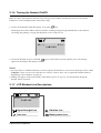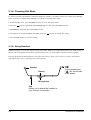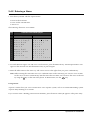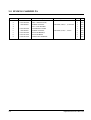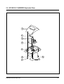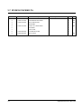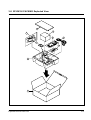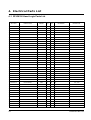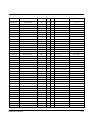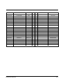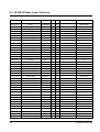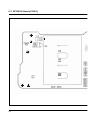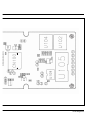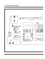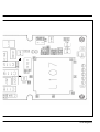
1
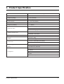
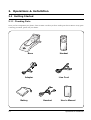
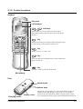
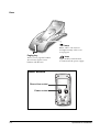
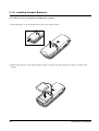
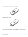
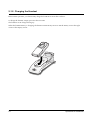
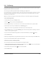
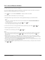
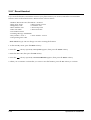
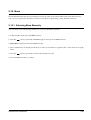
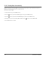
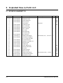
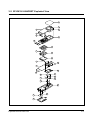
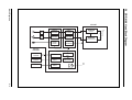
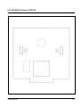
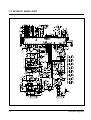
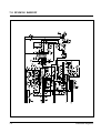
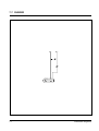
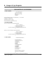
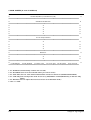
Cordless Telephone
SP-R6100
SERVICE
Cordless Telephone
Manual
CONTENTS
1. Product Specification
2. Operations & Installation
3. Exploded View & Parts List
4. Electrical Parts List
5. Block Diagrams
6. PCB Diagrams
7. Schematic Diagrams
8. Usage of Jig Program
CONTENTS
1. Product Specification
2. Operations & Installation
2-1 Getting Started
2-1-1 Checking Parts
2-1-2 Control Locations
2-1-3 Connecting Lines
2-1-4 Installing Handset Batteries
2-1-5 Charging the Handset
2-1-6 Turning the Handset On/Off
2-1-7 LCD Window Icon Descriptions
2-1-8 Choosing Dial Mode
2-1-9 Using Headset
2-2 General Functions
2-2-1 Making a Call
2-2-2 Camp On Busy
2-2-3 Receiving a Call
2-2-4 Caller ID Display
2-2-5 Last Number Redial
2-2-6 Battery Level Indicator
2-2-7 Out of Range Indicator
2-2-8 Adjusting Ring Volume
2-2-9 Adjusting Key Volume
2-2-10 Quick Switching to Vibration Mode
2-2-11 Registered Recall
2-2-12 Tone Dial Switchover
2-2-13 Paging
2-3 Using the Menus
2-3-1 Using the Soft Keys
2-3-2 Using the Index System
2-4 PhoneBook
2-4-1 Storing a Phone Number with a Name
2-4-2 Entering a Name
2-4-3 Dialling a Number in Phonebook
2-4-4 Searching for Numbers in Memory
2-4-5 Erasing All Numbers
2-4-6 Phonebook Options
2-5 Received Calls (Caller ID)
2-5-1 Viewing and Dialling a Number
2-5-2 Received Calls Options
2-6 Greeting Message
2-6-1 Greeting Message
2-7 Ring
2-7-1 Choosing Ring Tone
2-7-2 Adjusting Ring Volume
2-7-3 Choosing Alert Type
2-7-4 Unique Ring Tones for selected calls
2-7-5 Ring Delay Time
2-8 Settings
2-8-1 Tone/Pulse
2-8-2 Call Time Display
2-8-3 Base Number Display
2-8-4 Active Flip
2-8-5 Language Selection
2-9 System
2-9-1 Call Barring
2-9-2 Registering a New Handset
2-9-3 Intercom Between Handsets
2-9-4 Call Transfer Between Handsets
2-9-5 Removing a Handset
2-9-6 Changing PIN (Personal Identification
Number)
2-9-7 Reset Handset
2-10 Base
2-10-1 Selecting Base Manually
2-10-2 Finding Base Automatically
2-10-3 Troubleshooting
3. Exploded View & Parts List
3-1 SP-R5200 HANDSET P/L
3-2 SP-R5200 HANDSET Exploded View
3-3 SP-R5200 BASE P/L
3-4 SP-R5200 BASE Exploded View
3-5 SP-R5200 PACKING P/L
3-6 SP-R5200 PACKING Exploded View
4. Electrical Parts List
4-1 SP-R6100 Hand Logic Parts List
4-2 SP-R6100 Base Logic Parts List
4-3 SP-R6100 KEY Parts List
4-4 SP-R6100 Charger Part List
4-5 PCB Array
5. Block Diagrams
5-1 SP-R6100 Base Logic Block Diagram
5-2 SP-R6100 RF Block Diagram
5-3 SP-R6100 Hand Block Diagram
6. PCB Diagrams
6-1 SP-R6100 Base PCB (I)
6-2 SP-R6100 Base PCB (II)
6-3 SP-R6100 Handy PCB (I)
6-4 SP-R6100 Handy PCB (II)
6-5 SP-R6100 Key PCB (I)
6-6 SP-R6100 Key PCB (II)
6-7 SP-R6100 Charger PCB (I)
6-8 SP-R6100 Charger PCB (II)
7. Schematic Diagrams
7-1 SP-R6100 Hand Logic
7-2 SP-R6100 Hand RF
7-3 SP-R6100 BASE LOGIC
7-4 SP-R6100 Base CLIP
7-5 SP-R6100 BASE RF
7-6 SP-R6100 HAND KEY
7-7 SP-R6100 CHARGER
8. Usage of Jig Program
1. Product Specification
Item
Description
Standard
DECT/GAP
Frequency Range
1.88~1.90 GHz
Channels
120 Duplex Channels
Carrier Power
² 250 mW (24dBm)
Modulation
GFSK
Frequency Stability
² ± 50kHz
Ni-MH:Standby Mode : 70hours
Operation Time
Talk Mode : 7hours
Charging time : 10hours
Ambient Temperature
Humidity
Weight
Dimensions
Normal : 15ûC~35ûC
Extreme : -10ûC~40ûC
5%~90%
Baseset : 120g
Handset : 100g
Baseset : 64✕160✕73 mm (HWD)
Handset : 115✕22✕46 mm (HWD)
Power Supply
Baseset Input : DC 5V 400mA
Battery
Ni-MH: 2.4V, 600 mAh
CTR 06
CTR 10
Compliance
CTR 22
EMC
NET4 (PSTN)
Product Specification
1-1
2. Operations & Installstion
2-1 Getting Started
2-1-1 Checking Parts
Once you have unpacked your phone, check to make sure that you have all the parts shown below. If any piece
is missing or broken, please call your dealer.
Handset
Base
Line Cord
Adapter
Battery
2-1
Handset
User’s Manual
Operations & Installation
2-1-2 Control Locations
Handset
Ear piece
LCD window
soft keys
Each of the two soft keys performs the function
indicated by the text above it (the bottom line in the
display).
C
INT
C
ABC
DEF
GHI
JKL
MNO
PQRS
TUV
WXYZ
key
Deletes characters from display. When using the menu
system, returns to the previous menu level.
key
Makes, answers, or ends a call.
INT
key
Activates intercom communications. Also switches the
phone on and off.
key
Quickly switches to the vibration mode.
Microphone
Rear
Headset jack
Volume keys
Battery cover
Charging points
Operations & Installation
Adjusts the volume.When you press and hold the up key in
standby mode with the flip cover closed, you can quickly
switch to the vibration mode. When using the menu system,
scrolls through the menu options and the phonebook memory.
2-2
Base
lamp
Blinks when a call comes in
and lights steadily when a call
is in progress.
Paging key
Allows you to page the handset.
Also used to register a new
handset with the base.
lamp
Lights steadily while the base
is connected to the power supply.
Base Bottom
Phone Line socket
DC5V
LINE
Power socket
2-3
Operations & Installation
2-1-3 Connecting Lines
1. Connect one end of the telephone line cord to the phone line socket on the bottom of the base unit, and the
other end to a standard phone wall jack.
2. Connect the modular end of the power adapter to the power socket on the bottom of the base unit, and the
other end to a standard AC wall outlet.
LINE
DC5V
To AC wall outlet
To phone wall jack
3. Route the cords through the recessed channel as shown.
DC5V
Operations & Installation
LINE
2-4
2-1-4 Installing Handset Batteries
The handset uses the rechargeable Ni-MH battery supplied.
1. Slide the battery cover in the direction of the arrow, then lift it off.
2. Remove old battery (if any), then plug the battery connector into the socket shown below, and insert the
battery.
2-5
Operations & Installation
3. Replace the battery cover. Make sure that the cover is properly aligned.
4. Slide the cover up until it snaps shut.
Notes:
¥ The battery needs to be replaced if it does not recover its full storage capacity after recharging.
¥ When replacing battery, only use SAMSUNG-approved battery. For details, see ÔSpecificationsÕ on page 65 or
ask your nearest service center.
Operations & Installation
2-6
2-1-5 Charging the Handset
Before initial operation, you should fully charge the handset for more than 10 hours.
To charge the handset, simply place it in the base unit.
The handset can be charged facing up.
When the handset battery is charging, the handset automatically turns on and the battery icon in the right
corner of the display scrolls.
2-7
Operations & Installation
2-1-6 Turning the Handset On/Off
When you place the handset in the base unit to charge it, the handset automatically turns on. To turn the
handset on or off in Standby mode, follow these steps:
1. To turn on the handset when the display is off, press
INT
key.
The display shows the handset and base number, and the greeting message SAMSUNG as shown below.
(To change the greeting, see page 42) The phone is now ready for use.
HS( 1 )
BS ( 1 )
SAMSUNG
2. To turn the handset off, press and hold INT key for about three seconds until the power-off message
appears in the display. The display turns off.
Notes:
¥ If you purchase an additional handset, you must register the handset to a base. If not, the display shows Fail
to Register when you turn it on and only two soft keys work to allow you to register the handset. Refer to
ÔRegistering a New HandsetÕ on page 54.
¥ Nothing will appear in the LCD window when battery power is very low. You should fully charge the
handset before operation.
2-1-7 LCD Window Icon Descriptions
HS( 1 )
BS ( 1 )
SAMSUNG
Signal Strength icon
Vibration icon
Line icon
Battery status icon
Operations & Installation
2-8
2-1-8 Choosing Dial Mode
In order to provide compatibility with most telephone systems, your phone can be set to either pulse-dialling
(same as rotary), or tone dialling (DTMF). Your phone is preset to tone mode.
1. In the Standby mode, press the Menu soft key to access the menu mode.
2. Press the
soft key repeatedly until Settings appears, then press the Select soft key.
3. Tone/Pulse is displayed. Press the Select soft key.
4. The options are displayed; Pulse and Tone. Press the
soft key to change the setting.
5. Press the OK soft key to save the setting.
2-1-9 Using Headset
With the headset, you can talk without using your hands. When you connect the headset to the headset jack on
the left side of the phone, the headset operates in the same way as the phoneÕs speaker and microphone.
Pressing the button on the headset for more than one second allows you to answer or end a call(without
opening the flip cover or pressing a key on the phone).
Speaker
Button
To the geadset jack
(
) on the left side
of the phone.
Microphone
Clip
Allows you to attach the headset to
your clothes, for example.
2-9
Operations & Installation
2-2 General Functions
2-2-1 Making a Call
1. Open the flip cover, and press
key. You hear a dial tone.
Note: If you turn the Active Flip feature on, you do not need to press the
key. For details, see page 50.
2. Dial the desired phone number by using the number keypad.
Note: You can store telephone numbers in Phonebook memory and dial the numbers using the assigned
memory address. Refer to ÔPhonebookÕ on page 32.
3. When the other person answers, speak.
4. To end the call, either close the flip cover or press
key.
Notes:
¥ If you turn the ÔCall Time DisplayÕ feature on, the LCD
window displays the call time. For details, see ÔCall Time DisplayÕ on page 49.
¥ To make a call to the last number you dialled, use the ÔRedial Ô feature. For details, refer to ÔLast Number
RedialÕ on page 23.
You can enter the desired phone number in the Standby mode, and then dial the number. This way of dialling
allows you to make corrections to the number before dialling. Follow these steps:
1. Enter a telephone number. Check the number in the LCD window.
Notes:
¥ If you make a mistake while entering a number, press the C key to clear the last digit and correct the
number.
¥ If you press and hold the C key for more than one
second, all digits you have entered are cleared and the phone returns to the Standby mode.
2. When the number appears correctly, press
Operations & Installation
key to dial the number.
2-10
2-2-2 Camp On Busy
(Available only when you have more than one handset)
This feature allows your handset to wait for connection to the telephone line currently engaged by another
handset. Your handset rings when the telephone line becomes free.
1. You hear a short busy tone if you open the flip cover or press
telephone line.
key while another handset engages the
The display shows the handset number currently engaging the line. Your handset is automatically camped
on the line.
Note: To cancel this feature, press
mode.
key any time before the line is free. The handset returns to Standby
2. Your handset rings and the window displays FREE when the line becomes free.
3. Press
key to engage the line while the handset rings.
Notes:
¥ If an incoming call arrives while your handset rings to tell you the line is free, the ÔCamp On BusyÕ feature is
automatically cancelled and an incoming ring sounds.
¥ Several handsets can be camped on the busy line in
chronological order. When the line becomes available to you, the LCD window displays FREE, and other
handsets will display your handset number following the word BUSY.
¥ When your handset rings and the window displays FREE, press the key within 10 seconds. Otherwise, the
handset returns to the Standby mode.
2-11
Operations & Installation
2-2-3 Receiving a Call
When somebody calls you, the phone rings. Also, the (( )) icon in the middle of your handsetÕs display and
the telephone lamp on the left of the base will start to blink.
The callerÕs phone number will be displayed if the telephone network has transmitted the necessary
information.
1. If the handset is on the base, pick up the handset and speak. Or
If the handset is out of the base, open the flip cover and speak. Or
If the handset is in the Standby mode with the flip cover open, press
Note:
key.
key and INT key will not work for three seconds after the flip has been opened to receive a call
in order to prevent the phone from being disengaged.
2. To end the call, close the flip cover or press
key.
Note: If you set the ÔRing Delay TimeÕ feature, you can turn the handset ringer off for the specified time when a
call comes in and other handsets are ringing. Refer to ÔRing Delay TimeÕ on page 48.
Operations & Installation
2-12
2-2-4 Caller ID Display
Caller ID displays the callerÕs name and number, as well as the date and time that the call was received. This
feature is available on your phone if the callerÕs network transmits the necessary information. You can use this
feature only when the callerÕs service network transmits the callerÕs information.
12345678
ELIZABETH
The caller’s number
and name
Notes:
¥ The number of unanswered missed calls (if any) will be displayed.
Call(1)
There is one missed call.
Your phone keeps track of the last 20 calls received. Refer to ÔReceived CallsÕ on page 40 to check and dial the
numbers.
¥ If a caller has chosen to withhold their number, you will see ID NOT RECEIVED in the display.
¥ If a callerÕs number is not available, you will see ID NOT RECEIVED in the display.
2-13
Operations & Installation
2-2-5 Last Number Redial
Your phone allows you to call the most recently dialled numbers again. The phone stores the last 10 numbers
you called.
To Dial the Last Number
1. Press the Redials soft key in the Standby mode. The last number you dialled is displayed.
2. Press
key to dial the last number.
To View and Dial Any of Last 10 Numbers
1. Press the Redials soft key in the Standby mode.
2. Press the
soft key to scroll through the redial memory.
Each time you press the key, the numbers you dialled are displayed with the memory cell number. Cell 01
stores the last number and cell 10 stores the oldest number.
3. Press
key to dial the selected number.
Notes:
¥ If there is no number dialled, Redials Empty is displayed.
¥ You can modify the number displayed by using C key before pressing
key .
To Erase All Numbers In Redial Memory
1. Press the Redials soft key in the Standby mode.
2. Press the All Erase soft key. The display prompts you to confirm the setting.
3. Press the Yes soft key. You hear a beep and the phone returns to the Standby mode after clearing the redial
memory.
Operations & Installation
2-14
2-2-6 Battery Level Indicator
A
icon is continuously displayed in the upper line of the LCD window. The
your battery. The more bars you see, the more power you have left.
icon shows the level of
HS(1)
BS(1)
SAMSUNG
Flat
Full
When the battery is weak and a few minutes of talk time remain, you will hear a warning tone and the
icon blinks.
When the battery becomes too weak for the phone to operate, the handset will automatically turn off. Place the
handset on the base unit to charge the handset battery.
2-2-7 Out of Range Indicator
Your phone indicates the received signal strength through the strength icon. The more bars you see, the
stronger the signal is. If the handset is too far from the base unit and the handset cannot properly engage the
telephone line, the
icon blinks in the LCD window.
Signal
Strength Icon
HS(1)
BS(1)
SAMSUNG
If you move out of range during a call, the telephone line might be disconnected and the handset returns to the
Standby mode. Check if the icon blinks in the LCD window. If so, move the handset closer to the base unit.
2-15
Operations & Installation
2-2-8 Adjusting Ring Volume
During calls, pressing the
or
keys on the side of the phone affects the ear piece volume.
You can adjust the volume from level 1 to 5, and it is preset to level 3. The voice volume is displayed as bars in
the LCD window. The more bars you see, the louder the volume is.
Vo i c e Vo l u m e
[ _
]
Flash
Redials
Ear piece volume indicator
2-2-9 Adjusting Key Volume
In the Standby mode with the flip cover open, press
or
key on the side of the phone .
You can adjust the volume from level 0 to level 5, and it is preset to level 3. The key volume is displayed as
bars in the LCD window. The more bars you see, the louder the volume is. No bar, no key beep.
2-2-10 Quick Switching to Vibration Mode
You can quickly switch your phone to vibration mode with a touch of the
key or
phone. This feature provides a convenient way to mute your phoneÕs ringer quickly.
Press and hold the
key or
on the left side of the
on the left side of the phone (with the flip cover closed) in the Standby
mode. Alert Type Vibration is displayed for a second. Also, the
icon appears. Your phone switches to the
vibration mode immediately.
Press and hold the
key or
on the left side of the phone (with the flip cover closed) again to resume the
phoneÕs alert type which was previously set through the Ring Tone option under Ring menu; see page 43 for
further details.
Operations & Installation
2-16
2-2-11 Registered Recall
You can place a new call directly after a call or transfer a call to another extension under PABX, using this
feature.
To send a flash, simply press the Flash soft key while the line is engaged. The display shows F.
2-2-12 Tone Dial Switchover
To access certain services such as voice mail or interactive telephone system features, it is necessary to use tone
dialling. When your phone is set to the pulse mode, DTMF dialling is available.
1. Press the asterisk key (
dial mode temporarily.
) while on the phone in the pulse dial mode. Your phone is converted to the tone
2. When you press the Flash soft key or end the call, the phone automatically returns to the pulse mode.
2-2-13 Paging
You can page your handset from the base unit. Using this feature, you can find where the handset located.
Press the Paging key on the base unit. The left lamp marked
registered with the base will ring for about 10 seconds .
on the base blinks and all handsets
Note: If an incoming call comes in while the handset is being paged, the handset stops paging and sounds the
ringer.
2-17
Operations & Installation
2-3 Using the Menus
A two-level menu structure is available to set the various options available on your phone. You can set the
menu options in two different ways, via the soft keys or by using the index system.
2-3-1 Using the Soft Keys
The two soft keys are used in the following ways.
Key
Purpose
Left soft key
Enters the menu structure.
Selects the option displayed.
Right soft key
Moves to the next option on the same
level that is being displayed.
You can also use the
or
key on the left side of the phone to move to the next or previous option on the
same level as the one displayed.
To go back to the previous menu level, use the
C
key.
Example: Accessing the Ring Delay option
1. Press the Menu soft key to access the menu mode.
2. Press the
soft key repeatedly until Ring appears.
Ring
Select
4
3. Press the Select soft key to access the Ring menu.
4. Press the
soft key repeatedly until Ring Delay appears.
Ring Delay
OFF
Select
4.5
5. Press the Select soft key to access the Ring Delay option. Now you are connected to the Ring Delay option.
Operations & Installation
2-18
2-3-2 Using the Index System
Each menu option is assigned a hierarchical number. You will find the number in the lower right corner of the
display, next to
(refer to the display diagram above). You can use this number to access the corresponding
option directly. Simply press the Menu soft key to access the menu mode and key in the required number.
Example: Accessing the Ring Delay option
1. Press the Menu soft key to access the menu mode.
2. Press
3. Press
2-19
GHI
JKL
to access the Ring menu.
to access the Ring Delay option. Now you are connected to the Ring Delay option.
Operations & Installation
2-4 PhoneBook
The Phonebook allows you to store frequently used phone numbers and their associated names in your
personal directory so that you can easily make a call without having to remember or enter the phone number.
You can store up to 70 numbers.
2-4-1 Storing a Phone Number with a Name
1. In the Standby mode, enter the desired number (up to 24 digits).
2. Press the Save soft key. Enter Name ? appears and the cursor blinks.
3. Enter the name (up to 10 digits) for the number, then press the OK soft key. Refer to ÔEntering a NameÕ on
opposite page.
Note: If you make a mistake while entering a name/number or if you want to edit a name/number, press
the C key. Each time you press the key, the last letter/digit is cleared. To clear all letters/digits,
press and hold the C key. Then enter the correct name/number.
4. The first available memory address that the number can be saved to will blink.. If you want to find another
memory address, enter the desired address number or scroll the memory addresses by using the
soft
key.
5. Press the Select soft key to save the setting.
Note: If you select an address that already has a number stored under it, you are asked if you want to
overwrite the address with the newly entered number. If you are, press the Yes soft key. If not, press
the No soft key or the C key.
Operations & Installation
2-20
2-4-2 Entering a Name
1. Press the key labeled with the required letter:
¥ Once for the first letter
¥ Twice for the selected letter
¥ And so on
The following characters are available:
Key
Characters in the Order Displayed
Upper Case
1
2
3
4
5
6
7
8
9
0
Space .
A B C
D E F
G H I
J K L
MN O
P Q R
T U V
WX Y
0 , :
1
2
3
4
5
6
S
8
Z
;
!
€
ƒ
Q
L
„
7
†
9
Ô
? & i À ¤
• ®‚ G
D F
Y
¯ …
P S X
W
Ò / =
Lower Case
Space %
a b c
d e f
g h i
j k l
m n o
p q r
t u v
w x y
0 - +
@
2
3
4
5
6
s
8
z
(
_ £ $ ´ Û
ˆ Š Œ ¾
• Ž
“
– ¿ ˜ š
7 §
• Ÿ
9
) * # < >
2. To switch between upper case and lower case characters, press the Case soft key. All subsequent letters will
appear in the selected case until the Case soft key is pressed again.
3. Select the other letters in the same way. The cursor moves to the right when you press a different key.
Note: When entering the same letter twice (or a different letter on the same key), just wait for a few seconds
for the cursor to move automatically, and then select the next letter. You can move the cursor to the left
by using the
key on the side of the phone. To delete letters, use the C key.
Using a Pause
A pause is useful when you access an interactive voice response system, such as an automated banking system.
A pause delays dialling for 3 seconds.
If you want to insert a dialling pause between numbers, press the Pause soft key. P appears at the pause entry.
2-21
Operations & Installation
2-4-3 Dialling a Number in Phonebook
Once you have stored phone numbers in the phonebook memory, you can dial them easily whenever you
want.
One-Touch Dialling
Memory addresses 01 through 09 are special one-touch addresses. You can dial the phone numbers stored in
the Phonebook memory from 01 through 09 simply by pressing one key.
In the Standby mode, press and hold the second digit of the memory address containing the number to be
dialled.
For example: Address no. 09
Press
and hold. The number stored is
displayed, then dialled.
WXYZ
Two-Touch Dialling
In the Standby mode, press the first digit briefly, then hold down the second digit of the memory address.
For example: Address no. 23
Press
briefly and hold down
.
The number stored is displayed, then dialled.
ABC
Operations & Installation
DEF
2-22
2-4-4 Searching for Numbers in Memory
If you do not remember which telephone numbers have been stored in the various memory addresses, you can
scan through the memory until you find the one you are looking for.
By Name
1. Press the Menu soft key. Phonebook appears.
2. Press the Select soft key to access the Phonebook menu. The phonebook options are displayed. The option
in bold type will be selected when you press the Select soft key.
3. Press the Select soft key to access the Find Name option. Enter Name ? is displayed.
4. Enter all or part of the name by using the number key marked with the desired letter.
Example: Enter A to find all names beginning with the letter A.
5. Press the View soft key. The first name is displayed with the memory address number and the telephone
number
Note: If the message Data is not found is displayed, the name matching the request is not in the memory.
6. If the name shown is not the desired one, use the
7. If you want to call the selected number, press the
soft key to scroll through the stored names.
key.
By Address Number
1. Press the Menu key. Phonebook appears.
2. Press the Select soft key to access the Phonebook menu. The phonebook options are displayed.
3. Press the
soft key until the Find Address option is selected, then press the Select soft key. Enter Address ?
is displayed.
4. Enter the desired address number, then press the View soft key. The phone number and associated name
(if any) are displayed.
Note: If the address is empty, Data is not found is displayed. Then the display shows the first available
address in which a phone number is stored.
5. Use the
soft key to display the next or the previous memory address.
6. If you want to call the number, press the
2-23
key.
Operations & Installation
2-4-5 Erasing All Numbers
1. Press the Menu soft key. Phonebook appears.
2. Press the Select soft key to access Phonebook menu. The phonebook options are displayed.
3. Press the
soft key until All Erase is selected, then press the Select soft key. You are asked if you are sure
you want to erase all numbers stored in your phonebook memory.
4. Press the Yes soft key to confirm the deletion.
2-4-6 Phonebook Options
When you are viewing a number in the Phonebook, Options appears above the left soft key to allow you to
access the phonebook options, described in the following paragraphs.
Accessing to the Options
1. Press the Options soft key when it appears. The options are displayed.
2. Press the
soft key until a desired option is selected. The option in bold type will be selected.
3. Press the Select soft key.
Edit Name
Edit the name by using the keypad and the
name, see page 33.
C
key, then press the OK soft key. For details on entering a
Your phone displays the newly edited name, its number and its address number.
Edit Number
Edit the number by using the keypad and the C key, then press the OK soft key. Your phone displays the
newly edited number, its name and its address number.
Erase
If you press the Select soft key when Erase is selected, you are asked to confirm the deletion. Press the Yes soft
key to confirm the deletion.
Operations & Installation
2-24
2-5 Received Calls (Caller ID)
When you receive a call, the callerÕs phone number is shown on your phoneÕs display, if it is available from the
network on which the call was made. The last 20 numbers received are stored in your phone and you can view
the list and dial the numbers.
2-5-1 Viewing and Dialling a Number
1. Press the Menu soft key. Phonebook appears.
2. Press the
soft key repeatedly until Received Calls appears.
3. Press the Select soft key. The LCD window shows the last callerÕs number, and the date and time when the
call was received, if the necessary information was transmitted from the callerÕs telephone network.
If the address number blinks, it means you missed the call.
If there is no number received, Received Calls Empty is displayed.
4. Scroll the memory by using the
5. To dial the selected number, press
2-25
soft key and choose the desired number.
key.
Operations & Installation
2-5-2 Received Calls Options
When you are viewing received numbers, Options appears above the left soft key to allow you to access the
received call options, described in the following paragraphs.
Accessing the Options
1. Press the Options soft key when it appears. The options are displayed.
2. Press the
soft key until a desired option is selected. The selected option is in bold type.
3. Press the Select soft key.
Save Book
You can save the selected number in your Phonebook memory.
Enter the name for the number and press the OK soft key. Then choose the address number and press the
Select soft key.
Erase
When you are asked to confirm that you want to erase the selected number, press the Yes soft key. The selected
number will be erased.
All Erase
When you are asked to confirm that you want to erase all numbers, press the Yes soft key. All received
numbers will be erased.
Operations & Installation
2-26
2-6 Greeting Message
This option allows you to enter a greeting message that will be displayed when your phone is in the Standby
mode. You can change the greeting message according to your own preference.
2-6-1 Greeting Message
1. In the Standby mode, press the Menu soft key.
2. Press the
soft key repeatedly until Greeting Message appears.
3. Press the Select soft key. The cursor is blinking. If you have already registered a greeting message, the
message is displayed.
4. Enter your personal greeting by pressing the alphanumeric keys on the number keypad. A maximum of 16
digits can be entered. For details on entering a name, see page 33.
Note: If necessary, use the
C
key to erase the current greeting message.
5. Press the OK soft key to save the setting.
Note: If you want to restore the greeting message to the default setting, SAMSUNG, erase all the existing
messages and press the OK soft key.
2-27
Operations & Installation
2-7 Ring
You can use the Ring menu to customize various sound settings such as ring volume, type and tone. Also you
can delay the ring for a specified time via the menu.
2-7-1 Choosing Ring Tone
You can define your own ring sound. Ten ring tones are available.The factory default setting is ÔTone 1Õ.
1. In the Standby mode, press the Menu soft key.
2. Press the
soft key repeatedly until Ring appears, then press the Select soft key. Ring Tone appears.
3. Press the Select soft key to access the option.
4. Press the
soft key repeatedly until you choose a desired ring tone. Each time you press the
the handset sounds the ring you have chosen.
soft key,
5. Press the OK soft key to confirm the setting.
2-7-2 Adjusting Ring Volume
1. In the Standby mode, press the Menu soft key.
2. Press the
soft key repeatedly until Ring appears, then press the Select soft key.
3. Press the
soft key repeatedly until Ring Volume appears, then press the Select soft key. The current
Ring Volume setting appears.
4. Press the
or
key on the side of the phone to choose the volume level you want.
Each time you press
or
key, the handset sounds the ring with the level you have chosen.
The ring volume is displayed as bars in the LCD window. The more bars you see, the louder the volume is.
5. Press the OK soft key to confirm the setting.
Operations & Installation
2-28
2-7-3 Choosing Alert Type
This option allows you to indicate how you wish to be informed of any incoming calls. The following options
are available.
1. In the Standby mode, press the Menu soft key.
2. Press the
soft key repeatedly until Ring appears, then press the Select soft key.
3. Press the
soft key repeatedly until Alert Type appears, then press the Select soft key.
The Alert type options are displayed:
¥ Ring: The handset rings using the ring tone selected via the ÔRing ToneÕ menu.
¥ Vibra + Ring: The handset vibrates first, then rings.
¥ Vibration: The handset vibrates but does not ring.
4. Press the
soft key to select the alert type, then press the OK soft key.
Notes:
¥ Your handset will ring when it is on the base unit, even if it has been placed in vibration mode.
¥ To switch to vibration mode quickly, press and hold the
key in the Standby mode. To resume the
handsetÕs alert type, press and hold the
key again in the Standby mode. Refer to page 26.
2-29
Operations & Installation
2-7-4 Unique Ring Tones for selected calls
This new feature allows you to distinguish between different callers by assigning unique ring tones to specific
numbers stored in your handset When a call is received from a specified number, you will hear a unique ring
sound that can only be heard when that specific number calls.
Note:
¥ This feature is only available if the telephone systems used by both you and the caller support Caller ID.
Please contact your telephone service provider for more information.
You can choose from ten different tones and assign these as unique ring tones for up to three different callers.
1. In the Standby mode, press the Menu soft key.
2. Press the
soft key repeatedly until Ring appears, then press the Select soft key.
3. Press the
soft key repeatedly until Unique Ring Tone appears, then press the Select soft key.
The first ring address and its settings (if already registered) are displayed.
4. Press the
soft key to choose the ring address you want, then press the Options soft key.
5. Press the Select soft key to choose the Ring Tone option. Available ring tones are displayed.
6. Press the
soft key to choose the ring tone, then press the OK soft key.
7. Press the Options soft key.
8. Press the
soft key to select the Enter Number option, then press the Select soft key.
9. Enter the number you want to designate, then press the OK soft key.
10. Enter the name for that number, then press the OK soft key. Refer to ÔEntering a NameÕ on page 33.
To Deactivate a NumberÕs Unique Ring Tone
You can selectively deactivate a numberÕs unique ring by erasing that number.
1. In the Unique Ring Tone mode (see steps 1 through 3 on opposite page), use the
ring address containing the number you want to erase.
soft key to select the
2. Press the Options soft key.
3. Press the
soft key until the Erase option is selected, then the Select soft key.
4. When you are asked to confirm the setting, press the Yes soft key.
Operations & Installation
2-30
2-7-5 Ring Delay Time
If you activate the ring delay time, your handset will not ring for a specified delay time while other handsets
are ringing. If you wish, you can answer the call within the delay time on your handset.
1. In the Standby mode, press the Menu soft key.
2. Press the
soft key repeatedly until Ring appears, then press the Select soft key.
3. Press the
soft key repeatedly until Ring Delay appears, then press the Select soft key.
4. The ring delay time options are displayed. The current setting is in bold type. Press the
the ring delay time.
soft key to select
You can choose from ÔOFFÕ to 30 seconds using increments of 5 seconds. Selecting ÔOFFÕ deactivates the
feature.
5. Press the OK soft key to save the setting.
2-31
Operations & Installation
2-8 Settings
Many different features of your phone can be customized to suit your preferences. All of these features are
accessed via the Settings menu.
2-8-1 Tone/Pulse
Refer to page 2-2-12.
2-8-2 Call Time Display
If you turn this feature on, the handset automatically times the duration of calls. The handset displays the call
duration both during your call and for a few seconds after your call is completed. The feature is preset to ÔONÕ.
1. In the Standby mode, press the Menu soft key.
2. Press the
soft key repeatedly until Settings appears, then press the Select soft key.
3. Press the
soft key repeatedly until Call Time appears, then press the Select soft key. The Call Time
options are displayed; OFF or ON.
4. Press the
soft key to turn the feature OFF or ON. The selected option is in bold type.
5. Press the OK soft key to save the setting.
2-8-3 Base Number Display
This feature allows the phone to display the base number currently in use while in the Standby mode. The
feature is preset to ON at factory.
1. In the Standby mode, press the Menu soft key.
2. Press the
soft key repeatedly until Settings appears, then press the Select soft key.
3. Press the
soft key repeatedly until Base Number appears, then press the Select soft key.
4. The Base Number options are displayed; OFF or ON. Press the
The selected option is in bold type.
soft key to turn the feature OFF or ON.
5. Press the OK soft key to save the setting.
Operations & Installation
2-32
2-8-4 Active Flip
This feature allows you to automatically engage the telephone line by opening the flip cover. When this feature
is set to ON, there is no need to press the
key. This feature is preset to OFF at factory.
1. In the Standby mode, press the Menu soft key.
2. Press the
soft key repeatedly until Settings appears, then press the Select soft key.
3. Press the
soft key repeatedly until Active Flip appears, then press the Select soft key.
4. The Active Flip options are displayed: OFF or ON. Press the
selected option is in bold type.
soft key to turn the feature OFF or ON. The
5. Press the OK soft key to save the setting.
2-8-5 Language Selection
You can select a display language. 8 different languages are available.
1. In the Standby mode, press the Menu soft key.
2. Press the
soft key repeatedly until Settings appears, then press the Select soft key.
3. Press the
soft key repeatedly until Language appears, then press the Select soft key.
4. The language options are displayed. The currently selected language is in bold type. Press the
to select a language.
soft key
5. Press the OK soft key to save the setting.
2-9 System
Up to six handsets can be registered and operated from your base unit. You can register and remove a handset
through the System menu. You can also reset the handset to its default configuration.
2-33
Operations & Installation
2-9-1 Call Barring
It is possible to set the phone to restrict numbers that can be dialled. The phone cannot dial a phone number
beginning with the numbers that you specify.
You can set up to 4 different restricted numbers containing up to 4 digits each.
If you turn the feature on, the handset requires a PIN code when the restricted number is dialled. If you fail to
enter the correct PIN code three times successively, your phone returns to the Standby mode. If you enter a
correct PIN, you can make calls.
Note: You can make an emergency call (112, 999) even when you activate the outgoing call barring option.
To Set Call Barring Numbers
1. In the Standby mode, press the Menu soft key.
2. Press the
soft key repeatedly until System appears.
3. Press the Select soft key to access the menu. You are asked to enter the PIN code. It is preset to 0000.
4. Enter the PIN code, then press the OK soft key. Call Barring appears.
Note: If you enter the wrong PIN number, the handset returns to the Standby mode.
5. Press the Select soft key to access the Call Barring option. The first barring address containing a restricted
number, if already registered, appears.
6. If you want to choose another barring address, select the desired address by using the
soft key.
7. Press the Edit soft key.
8. Enter up to 4-digit number by using the numeric keys that you want to restrict, then press the OK soft key.
9. If you want to block another number, repeat steps 6 through 8.
To Deactivate a Specific Call Barring Number
You can selectively deactivate the restricted number by erasing the number.
1. In the Call Barring mode (see steps 1 through 5 on opposite page), use the
containing the restricted number you want to deactivate.
2. Press the Edit soft key, then use the
C
soft key to select the address
key to erase the number.
3. Press the OK soft key.
Operations & Installation
2-34
2-9-2 Registering a New Handset
The handset supplied with the base unit is already registered as handset 1. Each additional handset you
purchase must be registered to the base unit.
1. Press and hold the Paging key on the base for more than 3 seconds. The light is blinking.
2. Press the Menu soft key on the handset.
3. Press the
soft key repeatedly until System appears, then press the Select soft key. You are asked to enter
the PIN code. It is preset to 0000.
4. Enter the PIN code, then press the OK soft key.
5. Press the
soft key repeatedly until Registration appears.
6. Press the Select soft key. The available bases are displayed. The selected base to which your handset is
registered has a check mark on its right side.
7. Select a base by using the
soft key, then press the Select soft key. Please wait appears for a short time,
then the LCD window displays the ID of the base unit.
8. Press the OK soft key.
9. Enter 9234, the Authentication Code, which is preset at factory, then press the OK soft key.
10. When the registration is properly completed, the handset returns to the Standby mode and displays the
base number and the handset number.
11. Unplug the power cord and then plug it in again.
Notes:
¥ If you have registered the handset to several bases, and the base number you select at step 7 is already used
for another base, you will be asked to confirm that you want to overwrite. If you press the Yes soft key, the
old information is cleared and the base number will be used for your newly selected base. To keep old
information, press and hold the C key to cancel the setting, then start over again with a different base
number.
¥ The time limit for registering a handset to a base is 60 seconds. The registration will be automatically
cancelled when this time has elapsed.
¥ If you fail to register the handset, the handset displays Fail to Register.
2-35
Operations & Installation
2-9-3 Intercom Between Handsets
(Available only when you have more than one handset)
If you have multiple handsets registered with the base, two handsets can talk to each other on an internal
intercom call, while a third handset can be on an external call.
1. Press
INT
key on your handset. INTERCOM -> displays and the cursor blinks.
2. Enter the number of the handset (1-6) you want to page.
3. The paged handset rings. The LCD window on the paged handset displays your handset number.
Notes:
¥ If you enter a handset number that does not exist, the handset shows IT IS NOT REGISTERED and
sounds an error tone.
¥ To cancel intercom, close the flip or press either
key or INT key.
¥ You cannot adjust the intercom ringer volume.
4. To answer the call from you, the paged handset should open the flip or press either
INT
or
key.
5. When the paged handset answers you, speak.
6. To end the call, close the flip or press either
INT
or
key.
Notes:
¥ If an external call comes in during an intercom conversation, you will hear beeps. When you hear the low
beeps, finish the intercom call by pressing INT or
key. The external ring sounds. Press
key to
answer the call.
¥ When you make an intercom call, if Busy appears in the display and you cannot communicate with the
paged handset, the paged handset is engaged with an outside party. Your handset is automatically camped
on to the busy station, and when the busy station becomes free, both handsets will ring.
¥ When you make an intercom call, if INTERCOM IS USED is shown in your display, the handset you tried
to connect with is engaged with another internal line.
¥ In step 3, if the paged person opens the flip cover to answer the call from you, that person does not need to
press INT or
key.
Operations & Installation
2-36
2-9-4 Call Transfer Between Handsets
(Available only when you have more than one handset)
You can transfer a call from one handset to another.
1. During a telephone conversation, press INT key. Your caller will be put on hold and will hear music.
INTERCOM -> displays and the cursor blinks.
2. Enter the number (1 through 6) of the handset to which you want to transfer the call.
3. The paged handset rings. To answer the call from you, the paged handset should open the flip cover or press
either INT key or
key.
4. You can speak with the handset (Intercom).
5. To transfer the external call to the paged handset, close the flip or press
To cancel the call transfer and talk with the outside party again, press
key.
INT
key.
2-9-5 Removing a Handset
1. In the Standby mode, press the Menu soft key.
2. Press the
soft key repeatedly until System appears, then press the Select soft key.
3. Enter the PIN code, then press the OK soft key.
4. Press the
soft key repeatedly until Remove Handset appears, then press the Select soft key.
5. The selected base number to which your handset is currently registered appears. Press the Yes soft key.
6. When the handset is properly removed, Fail to Register is displayed. Now, you cannot use the handset with
the base unit unless you register the handset back to it.
Note: If the handset is registered to more than one base unit, and you want to use the handset with other base
units, you have to choose one of the other bases available. Refer to ÔSelecting Base ManuallyÕ on page 64.
2-37
Operations & Installation
2-9-6 Changing PIN (Personal Identification Number)
The PIN is required when you access System menus. The PIN is preset to Ô0000Õ at factory. You can change the
PIN code.
1. In the Standby mode, press the Menu soft key.
2. Press the
soft key repeatedly until System appears, then press the Select soft key.
3. Enter the PIN code, then press the OK soft key.
4. Press the
soft key repeatedly until Change PIN appears, then press the Select soft key.
5. New PIN [ ] is displayed. Enter a new PIN code, then press the OK soft key. The LCD window does not
display the PIN code you entered in order to maintain secrecy.
Note: It must be 4 digits. If you make a mistake, you can correct the number by using the
C
key.
6. Enter the new PIN code again to confirm the number, then press the OK soft key.
Notes:
¥ If you enter a different number from the new code, the phone sounds an error beep, and returns to the
previous screen.
¥ If you change the PIN code and then forget it, you will have to contact your local service center.
¥ If you want to exit from the Change PIN mode while changing PIN, press the Exit soft key.
Operations & Installation
2-38
2-9-7 Reset Handset
If you reset the handset, all numbers stored in your phone memory are cleared, and all the user-selectable
features return to the manufacturerÕs default status as shown below:
¥ Redials/Received Calls/Phonebook : All Erase
¥ Ring Tone: Tone 1
¥ Ring Volume: Level 3
¥ Ring Delay: OFF
¥ Call Time: ON
¥ Base Number: ON
¥ Active Flip: OFF
¥ PIN code: 0000
¥ Auto Find: OFF
¥ No number barred
¥ Greeting Message: SAMSUNG
¥ Key Volume : Level 1
¥ Voice Volume : Level 3
¥ Unique Ring Tone: OFF
Note: The Dial type will not change even after resetting the handset.
1. In the Standby mode, press the Menu soft key.
2. Press the
soft key repeatedly until System appears, then press the Select soft key.
3. Enter the PIN code, then press the OK soft key.
4. Press the
soft key repeatedly until Reset Handset appears, then press the Select soft key.
5. When you are asked to confirm that you want to reset the handset, press the Yes soft key to confirm.
2-39
Operations & Installation
2-10 Base
The SP-R6100 handset may be used with up to four base units. To use the handset with more than one base
unit, you must register the handset to each base unit. Refer to ÔRegistering a New HandsetÕ ON 2-9-2.
2-10-1 Selecting Base Manually
You can select a base unit through which you want your handset to operate.
1. In the Standby mode, press the Menu soft key.
2. Press the
soft key repeatedly until Base appears, then press the Select soft key.
3. Select Base is displayed. Press the Select soft key.
4. The available bases are displayed. The base to which your handset is registered has a check mark on its righthand.
5. Press the
soft key repeatedly to choose the desired base unit.
6. Press the Select soft key to confirm.
Operations & Installation
2-40
2-10-2 Finding Base Automatically
With the ÔAuto FindÕ feature set to ON, if you are moving around, and lose contact with the base unit, the
handset will automatically find the first available base unit.
The feature is preset to OFF.
1. In the Standby mode, press the Menu soft key.
2. Press the
soft key repeatedly until Base appears, then press the Select soft key.
3. Press the
soft key repeatedly until Auto Find appears, then press the Select soft key.
4. The display shows the current setting; OFF or ON. Press the
soft key to choose OFF or ON.
5. Press the OK soft key to confirm.
2-41
Operations & Installation
2-10-3 Troubleshooting
Symptom
Check
¥ Check that the power adapter is properly connected.
¥ Check that the telephone line cord is properly connected.
No operation
¥ Check that the handset is fully charged.
¥ Check that the handset batteries are installed properly.
¥ Check that the telephone line cord is properly connected.
No dial tone
¥ Check that the power adapter is properly connected.
The handset
seems to have
very short
battery life.
¥ Clean the charging points.
Warning beep
occurs when
making a call
¥ Check that the handset batteries are not in low status
Operations & Installation
¥ Consistently short battery life may indicate that
replacement of the batteries is necessary.
2-42
3. Exploded View & Parts List
3-1 SP-R6100 HANDSET P/L
Location No
Code No
1
2
3
4
5
6
7
8
9
10
11
12
13
14
15
16
17
18
19
20
21
22
23
24
25
26
27
28
GG74-00022A
GG72-00049A
GG74-00018A
GG72-00042A
3-1
GG68-30545A
GG73-00012A
GG72-00057A
GH75-00046A
GG73-00014A
GG73-00013A
GG72-00043A
6001-001110
GG71-00020A
GG71-00019A
GG72-00044A
GH74-10567A
GH31-10004A
GG74-00019A
GG74-00026A
GG74-00020A
GG72-00045A
6001-001060
GG68-00199A
GG72-00046A
Description
WINDOW-TAPE
WINDOW-LCD
TAPE-WINDOW
FLIP-COVER
MAGNETIC
LABEL(R)-FLIP
KEY-VOLUME
FRONT-COVER
MEC. HINGE
KEY-PAD
HOLDER-MIC
SUA. KEY-PBA
KEY-SPACER
SCREW-MACHINE
ANTENNA-WIRE(A)
SUA. LOGIC-BOARD
CONTACT-BASE
SHIELD-COVER(R/M)
SPONGE-SPK
VIBRATOR
TAPE-VIBRATOR
SPONGE-BUZZER
BUZZER
TAPE-BUZZER
REAR-COVER
SCREW-MACHINE
LABEL(R)-HANDSET
BATTERY-COVER
Specification
15X2Xt0.8
MACHINE, CH, +, M1.7X4.5
MACHINE, B, BH, +, M2X4
QÕty
1
1
1
1
1
1
1
1
2
1
1
1
1
4
1
1
2
1
1
1
1
1
1
1
1
4
1
1
SNA
SNA
SNA
SNA
SNA
SNA
SNA
SNA
Exploded View & Parts List
3-2 SP-R6100 HANDSET Exploded View
1
2
4
3
5
6
7
8
9
10
11
12
13
14
15
16
18
17
22
19
23
20
21
24
25
27
26
28
Exploded View & Parts List
3-2
3-3 SP-R6100 BASE P/L
Location No
Code No
1
2
3
4
5
6
7
8
9
10
11
12
13
14
15
16
GG72-00047A
GG72-00051A
6003-001051
GG72-00050A
GG72-00048A
GG73-00016A
GG72-00053A
GG75-00026A
6002-000352
3-3
GG71-00021A
6001-001110
GG72-00052A
6002-000397
GG73-00005A
GG68-00200A
Description
BASE-UPPER
BACK-COVER
SCREW-TAPTITE
LED-LENS
KEY-TOP
KEY-RUBBER
SHIELD-COVER(B)
MEC. TERMINAL
SCREW-TAPTITE
SUA. LOGIC BOARD
ANTENNA-WIRE(B)
SCREW-MACHINE
BASE-LOWER
SCREW-TAPTITE
FOOT-RUBBER(A)
LABEL(R)-BASE
Specification
TAPTITE, BH, +, 2, M2.6X8
TAPTITE, PWH, +, M2.5X4
MACHINE, CH, +, M1.7X4.5
TAPTITE, BH, +, M2X6
QÕty
1
1
1
1
1
1
1
1
4
1
2
4
1
4
4
1
SNA
SNA
SNA
SNA
SNA
SNA
SNA
Exploded View & Parts List
3-4 SP-R6100 BASE Exploded View
1
4
2
5
6
3
7
11
8
9
9
10
12
13
14
15
16
Exploded View & Parts List
3-4
3-5 SP-R6100 CHARGER P/L
Location No
Code No
1
2
3
4
5
6
7
8
9
GG72-00054A
GG75-00028A
6002-000352
3-5
GG72-00055A
6002-000397
GG73-00005A
GG61-40101A
GG68-00201A
Description
CHARGER-UPPER
MEC. TERMINAL(B)
SCREW-TAPTITE
SUA. CHG BOARD
CHARGER-LOWER
SCREW-TAPTITE
FOOT-RUBBER(A)
FOOT-RUBBER
LABEL ID-CHARGER
Specification
TAPTITE, PWH, +, 2, M2.5X4
TAPTITE, B, BH, +, M2X6
QÕty
1
1
1
1
1
4
2
2
1
SNA
SNA
SNA
SNA
SNA
SNA
SNA
SNA
SNA
Exploded View & Parts List
3-6 SP-R6100 CHARGER Exploded View
1
2
3
4
5
8
6
7
Exploded View & Parts List
9
3-6
3-7 SP-R6100 PACKING P/L
Location No
1
2
3
4
5
6
7
8
9
3-7
Code No
GG97-01753A
GG69-10874A
GG97-01752A
GG69-00026A
GG69-00025A
Description
USERS MANUAL
MEA BASE HOUSING
BOX-ADAPTOR
BATTERY
MEA. H/S HOUSING
EAR MIC.
TEL LINE
CUSHION-CASE
BOX-UNIT
Specification
QÕty
1
1
1
1
1
1
1
1
1
SNA
SNA
SNA
SNA
Exploded View & Parts List
3-8 SP-R6100 PACKING Exploded View
1
3
2
5
7
4
6
8
9
Exploded View & Parts List
3-8
4. Electrical Parts List
4-1 SP-R6100 Hand Logic Parts List
SEC CODE
VENDOR CODE
VENDOR
Q’T
SYM
0402-001075
MBR0520LT1
MOTOROLA
1
D
101
DIODE
0404-000116
BAS4004
SIEMENS
1
D
106
DIODE-SCHOTTKY
0405-001024
1SV276
TOSHIBA
2
D
505, 506
VARACTOR DIODE
0405-001054
BB833
SIEMENS
1
D
507
0406-001012
SM12
SEMTECH
1
ZD
1
TVS-DIODE
0407-000122
SDS 7000
KANGELE
4
D
102, 103, 104, 105
SW-DIODE
0409-001001
BAR63-03W
SIEMENS
1
D
500
PIN DIODE
0409-001023
BAR81W
SIEMENS
1
D
502
PIN DIODE
0501-000457
MMBT2222A
SEC
5
Q
101, 105, 104, 108, 109
TR-NPN
0501-000462
MMBT2907A
SEC
2
Q
104, 106
TR-PNP
0501-002222
BC807-25W
SIEMENS
2
Q
500, 501
TR-PNP
0504-001010
DTA143XUA
ROHM
1
Q
504
TR-PNP
REFERENCE
DESCRIPTION
DIODE
0505-001159
MGSF3454VT1
MOT
1
Q
103
0801-000302
TC74HC375AF
TOSHIBA
2
U
102, 104
LATCH IC
0801-002192
TC7S04F
TSB
1
U
103
CMOS-IC
1102-001100
AT27BV020
ATMEL
1
U
105
IC-EPROM
TR
1103-001158
AT24C32N-10SI-2.7
ATMEL
1
U
109
IC-EEPROM
1201-100153
PMB4819
SIEMENS
1
U
500
POWER AMP
1202-001022
TC75W56FU-TE12L
TSB
1
U
110
IC-VOLTAGE COMP
1203-001285
MIC5205-3. OBM5/TR
MICREL
1
U
111
IC-VOLTAGE REGULATOR
1205-001616
PMB5420
SIEMENS
1
U
501
RX IC
1205-001627
PMB5722
SIEMENS
1
U
107
BMC
1209-001226
PMB4220
SIEMENS
1
U
502
TX IC
2007-000138
RC1005J101CS
SEM
1
R
130
100, 1005
2007-000140
RC1005J102CS
SEM
10
R
104, 109, 146, 150, 151,
1K, 1005
501, 530, 535, 539, 545
2007-000141
RC1005J222CS
SEM
1
R
518
2.2K, 1005
2007-000143
RC1005J472CS
SEM
1
R
512
4.7K, 1005
2007-000148
RC1005J103CS
SEM
7
R
108, 112, 113, 132, 133, 149,
10K, 1005
538
2007-000153
RC1005J223CS
SEM
1
R
532
22K, 1005
2007-000155
RC1005J273CS
SEM
4
R
119, 137, 140, 531
27K, 1005
2007-000160
RC1005J683CS
SEM
1
R
121
68K, 1005
2007-000162
RC1005J104CS
SEM
4
R
127, 128, 152, 158
100K, 1005
2007-000163
RC1005J124CS
SEM
1
R
513
120K, 1005
2007-000164
RC1005J154CS
SEM
3
R
131, 134, 141
150K, 1005
2007-000171
RC1005J000CS
SEM
2
R
125, 156
0, 1005
2007-000172
RC1005J100CS
SEM
1
R
527
10, 1005
4-1
Electrical Parts List
SEC CODE
VENDOR CODE
VENDOR
Q’T
SYM
2007-000618
RC1608J240CS
SEM
1
R
103
24, 1608
2007-000775
RC1005J333CS
SEM
1
R
601
33K, 1005
2007-000839
RC1608J390CS
SEM
2
R
101, 102
39, 1608
2007-000982
RC1005J542CS
SEM
1
R
526
5.6K, 1005
2007-001316
RC1005J821CS
SEM
3
R
534, 540, 603
820, 1005
2007-001320
RC1005J182CS
SEM
4
R
122, 123, 543, 544
1.8K, 1005
2007-001323
RC1005J302CS
SEM
1
R
136
3K, 1005
2007-001333
RC1005J183CS
SEM
2
R
135, 139
18K, 1005
2007-001335
RC1005J363CS
SEM
2
R
126, 129
36K, 1005
2007-007001
RC1005J392CS
SEM
5
R
528, 529, 533, 541, 542
3.9K, 1005
2007-007063
SR73K2ATDOR1G
KOA
1
R
120
0.1, 2012
2007-007141
RC1005J241CS
SEM
1
R
537
240, 1005
2007-007310
RK73H1ETP8201F
KOA
1
R
115
8.2K, 1005
2007-007312
RC1005J203CS
SEM
1
R
107
20K, 1005
2007-007468
RK73H1ETP1213F
KOA
1
R
117
121K, 1005
2007-007538
RK73H1ETP5602F
KOA
3
R
116, 118, 138
56K, 1005
2007-007590
RK73H1ETP8202F
KOA
1
R
106
82K, 1005
2203-000138
GRM36X7R152K50PT
MURATA
1
C
514
1.5NF, 1005
2203-000189
GRM39V5V104Z25PT
NURATA
2
C
181, 155
100NF, 1608
2203-000233
GRM36COG101J50PT
MURATA
1
C
604
100PF, 1005
2203-000254
GRM36X7R103K16PT
MURATA
25
C
114, 116, 121, 131, 136, 141,
10NF, 1005
REFERENCE
DESCRIPTION
142, 145, 147, 157, 158,
161, 163, 165, 167, 168,
170, 172, 175, 176, 508,
518, 534, 560, 569
2203-000278
GRM36COG100D50PT
MURATA
36
C
130, 132, 135, 137, 138,
10PF, 1005
140, 156, 159, 160, 162,
164, 166, 169, 171, 173,
174, 502, 504, 512, 516,
523, 525, 526, 537, 565,
572, 573, 574, 579, 580,
581, 582, 595, 598, 608, 611
2203-000359
GRM36COG151D50PT
MURATA
2
C
589, 600
150PF, 1005
2203-000386
GRM36COG150D50PT
MURATA
2
C
513, 538
15PF, 1005
2203-000425
GRM36COG180J50PT
MURATA
1
C
150
18PF, 1005
2203-000628
GRM36COG220J50PT
MURATA
1
C
571
22PF, 1005
2203-000643
GRM36COG150D50PT
MURATA
1
C
602
24PF, 1005
2203-000679
GRM36COG240J50PT
MURATA
1
C
511
27PF, 1005
2203-000696
GRM36COG020C50PT
MURATA
2
C
539, 593
2PF, 1005
2203-000714
GRM36X7R332K50PT
MURATA
2
C
133, 139
3.3NF, 1005
Electrical Parts List
4-2
SEC CODE
VENDOR CODE
VENDOR
Q’T
SYM
2203-000799
GRM40X7R333K25PT
MURATA
1
C
129
2203-000870
GRM36COG030C50PT
MURATA
1
C
605
2203-000940
GRM36COG471J50PT
MURATA
2
C
180, 536
2203-001017
C1608TH1H040CT000
TDK
5
C
521, 548, 559, 563, 599
4PF, 1005
2203-001072
GRM36COG560J50PT
MURATA
1
C
543
56PF, 1005
2203-001140
GRM40X7R683K25PT
MURATA
7
C
120, 122, 125, 126, 127
68NF, 1608
REFERENCE
DESCRIPTION
33NF, 1608
3PF, 1005
470PF, 1005
128, 152
2203-001178
GRM36COG060D50PT
MURATA
3
C
541, 596, 597
6PF, 1005
2203-001201
GRM36COG070D50PT
MURATA
2
C
524, 527
7PF, 1005
2203-001259
GRM36COG080D50PT
MURATA
1
C
546
8PF, 1005
2203-001383
GRM36COGR5C50PT
MURATA
1
C
601
0.5PF, 1005
2203-001385
GRM36COG1R5C50PT
MURATA
1
C
592
1.5PF, 1005
2203-001405
GRM36X7R223K50PT
MURATA
1
C
535
22NF, 1005
2203-003027
06035A821JAT2A
AVX
1
C
544
820PF, 1608
2203-005056
GRM36COG6R8C50PT
MURATA
2
C
143, 149
6.8PF, 1005
2203-005061
GRM36Y5V104Z16PT
MURATA
1
C
547
100NF, 1005
2203-005065
GRM39V5V105Z10PT
MURATA
20
C
101, 102, 103, 104, 105,106
1uF, 1608
107, 108, 109, 110, 111, 112
113, 134, 154, 177, 178, 179
182, 183
2203-005138
GRM36X7R182K50PT
MURATA
1
C
520
1.8NF, 1005
2203-005148
GRM40X7R104K25PT
MURATA
3
C
124, 144, 148
100NF, 1608
2203-005281
GRM36COG1R5B50PT
MURATA
3
C
501, 552, 591
1.5PF, 1005
2203-005288
GRM36COG010B50PT
MURATA
2
C
528, 557
1PF. 1005
2203-005393
GRM36COG050B50PT
MURATA
1
C
562
5P, 1005
2203-005395
GRM36COG4R7B50PT
MURATA
1
C
540
4.7PF, 1005
2203-005443
GRM36COG03R3B50PT
MURATA
1
C
558
3.3PF, 1005
2203-005444
GRM36COG02R2B50PT
MURATA
2
C
550, 588
2203-005552
GRM36COG02R2B50PT
MURATA
5
C
529, 549, 553, 590, 610
2203-005565
GRM36COH102J25
MURATA
1
C
567
1NF, 1608
2301-001274
ECHU1C153JB5
PANASONIC
1
C
568
15NF, 3216
2404-000232
T491A475M010AS
KEMET
1
C
184
4.7uF/10V
2404-000259
T491C476M006AS
KEMET
1
C
115
47uF/6.3V, 6032
2404-001027
T491X337M006AS
KEMET
1
C
119
330uF/6.3V, 7343
2404-001032
T491B336M006AS
KEMET
2
C
123, 146
33uF/6.3V, 3528
2404-001107
595D107X0016C2T
SPRAGU
1
C
118
100uF/16V, 7132
2502-000125
TZV02Z060A110T00
MURATA
2
C
555, 564
2703-000143
MLF1608DR18KT
TDK
1
L
502
180nH, 1608
2703-000295
MLF1608DR22KT
TDK
1
L
509
220nH, 1608
2703-000373
LEM2520T680J
TAIYO
1
L
103
68uH
4-3
3PF, 1005
2.2PF, 1005
2.5-6PF (TRIMMER)
Electrical Parts List
SEC CODE
VENDOR CODE
VENDOR
Q’T
SYM
2703-001293
LL1608-FH82NJ
TOKO
1
L
505
2703-001722
LL1005-FH18NJ
TOKO
2
L
500, 510
18NH, 1005
2703-001790
LL1005-FH3N3S
TOKO
2
L
506, 507
3.3NH, 1005
2703-001785
BDS-5445-101K
BUJEON
1
L
101
100uH
2703-001793
BDS-4532-100M
BUJEON
1
L
102
100uH
2801-003780
SQ6U10368F2EED
SAMSUNG ELE
1
X
101
X-TAL
2802-001016
B69610-H1397-B306
SIEMENS
1
Y
500
TX RESONATOR
2903-001196
B69812-N1897-L820
SIEMENS
1
X
500
BPF FILTER
2904-001158
B3911-B8104-L100
SIEMENS
1
X
501
SAW FILTER
3002-001091
PKM35-4A40
MURATA
1
PZ
1
BUZZER
3009-001031
KR-152-150W
KIRIN
1
RC
1
RECEIVER
3710-000341
AXN720535P
MATSU
1
CN
100
CONNECTOR-SOCKET(20P)
3710-001105
24-8005-002-000-867
ELCOK
1
CN
105
CONNECTOR-SOCKET
REFERENCE
DESCRIPTION
82nH, 1608
3711-000827
53014-0210
MOLEX
1
CN
101
CONNECTOR HEADER
3722-001172
HSJ1621-019011
HOSIDEN
1
CN
103
JACK-AC POWER
GG39-00006A
KJ9906-22-01
SUNGJI IND
1
CHARGER WIRE1
GG39-00007A
KJ9906-22-02
SUNGJI IND
1
CHARGER WIRE2
500
GG42-00001A
SS-1809
SAMBO
1
ANT
GG43-00005A
SP-R6100
HANLIM
1
BT
1
GH07-00008A
HLM7451-010100
HOSID
1
U
101
GH31-10004A
FN31E30T070-6
TKPRTS
1
Electrical Parts List
ANTENNA
BATTERY PACK
LCD
VIBRATOR
4-4
4-2 SP-R6100 Base Logic Parts List
SEC CODE
VENDOR CODE
VENDOR
Q’T
SYM
0402-000318
SIZB60
PSHINDENGEN
1
BD
2
BRIDGE DIODE
REFERENCE
DESCRIPTION
0403-001047
BZX84C12
PHILIPS
2
ZD
1, 2
ZEMER DIODE
0403-001085
1SMB5927BT3
MOTOROLA
1
ZD
3
ZEMER DIODE
0404-000116
BAS40-04
SIEMENS
1
D
3
DIODE
0405-001024
1SV276
TOSHIBA
2
D
505, 506
0405-001054
BB833
SIEMENS
1
D
507
0406-001012
SM12
SEMTEC
1
ZD
4
0409-001001
BAR63-03W
SIEMENS
1
D
500
PIN DIODE
0409-001003
BAR64-05
SIEMENS
1
D
503
PIN DIODE
0409-001005
BAR80
SIEMENS
1
D
502
DUAL PIN DIODE
0501-000457
MMBT2222A
SEC
3
Q
2, 3, 5
0501-000481
MMBTA92
SEM
1
Q
14
TR
0501-000526
2SD999-CK
NEC
1
Q
9
TR
0501-002222
BC807-25W
SIEMENS
2
Q
500, 501
0502-000479
2SB798
NEC
2
Q
10, 11
TR
0502-001034
KSH350TM
SEC
1
Q
1
TR
0502-001053
MMSTA06
ROHM
1
Q
7
TR
VARACTOR DIODE
DIODE
ZENER DIODE
TR-NPN
TR-PNP
0504-001010
DTA143XUA
ROHM
1
Q
504
TR-NPN
0601-000274
CL-170YG-CD
CITIZEN
2
LED
1, 2
CHIP LED
0604-000138
PC357N4T
SHARP
1
U
7
PHOTO COUPLER
1103-001023
AT24C08N-10SI-2.7
MICROCHIP
1
U
10
EEPROM
1201-001408
PMB4820
SIEMENS
1
U
500
1203-000422
M5237ML-600D
MITSUBISH
1
U
9
1205-001616
PMB5420
SIEMENS
1
U
501
RX IC
1205-001628
PMB5725
SIEMENS
1
U
5
BMC
1209-001226
PMB4220
SIEMENS
1
U
502
TX IC
2003-000228
MOR1W, 22, J, TB
ABCO
1
R
77
R-METAL OXIDE
2007-000070
RC1608J000CS
SEM
10
R
1, 3, 4, 5, 6, 7, 8, 13, 14, 123
2007-000102
RC1608J104CS
SEM
1
R
9
2007-000109
RC1608J105CS
SEM
1
R
74
1M, 1608
2007-000121
RC1608J821CS
SEM
1
R
62
820, 1608
2007-000139
RC1005J221CS
SEM
2
R
75, 104
220, 1005
2007-000140
RC1005J102CS
SEM
3
R
504, 535, 545
1K, 1005
2007-000141
RC1005J222CS
SEM
1
R
518
2.2K, 1005
2007-000142
RC1005J272CS
SEM
1
R
505
2.7K, 1005
2007-000143
RC1005J472CS
SEM
3
R
30, 94, 512
4.7K, 1005
2007-000148
RC1005J103CS
SEM
9
R
18, 21, 22, 23, 25, 26, 51
10K, 1005
2007-000151
RC1005J153CS
SEM
4
R
34, 46, 96, 101
15K, 1005
2007-000153
RC1005J223CS
SEM
2
R
102, 532
22K, 1005
POWER IC
REGULATOR
0, 1608
100K, 1608
538, 539
4-5
Electrical Parts List
SEC CODE
VENDOR CODE
VENDOR
Q’T
SYM
REFERENCE
DESCRIPTION
2007-000155
RC1005J273CS
SEM
2
R
82, 531
2007-000159
RC1005J563CS
SEM
2
R
33, 100
56K, 1005
2007-000162
RC1005J104CS
SEM
3
R
44, 45, 47
100K, 1005
2007-000163
RC1005J124CS
SEM
1
R
513
120K, 1005
2007-000171
RC1005J000CS
SEM
6
R
16, 52, 68, 71, 97, 98
2007-000172
RC1005J100CS
SEM
1
R
527
10, 1005
2007-000775
RC1005J333CS
SEM
1
R
601
33K, 1005
2007-000840
RC3216J390CS
SEM
2
R
84, 85
39, 1/8W
2007-000982
RC1005J562CS
SEM
2
R
59, 526
5.6K, 1005
27K, 1005
0, 1005
2007-001134
RC1608J680CS
SEM
2
R
76, 124
68, 1608
2007-001301
RC1005J680CS
SEM
1
R
49
68, 1005
2007-001308
RC1005J201CS
SEM
1
R
103
200, 1005
2007-001313
RC1005J331CS
SEM
3
R
87, 88, 89
330, 1005
2007-001316
RC1005J821CS
SEM
1
R
540
820, 1005
2007-001320
RC1005J182CS
SEM
4
R
42, 43, 543, 544
1.8K, 1005
2007-001323
RC1005J302CS
SEM
2
R
500, 501
2007-001329
RC1005J752CS
SEM
1
R
99
2007-001333
RC1005J183CS
SEM
3
R
80, 81, 530
18K, 1005
2007-003013
RC1005J242CS
SEM
1
R
65
2.4K, 1005
2007-007001
RC1005J392CS
SEM
6
R
64, 528, 529, 533, 541, 542
3.9K, 1005
2007-007013
RC1005J912CS
SEM
1
R
86
9.1K, 1005
2007-007101
RC1005J433CS
SEM
1
R
79
43K, 1005
2007-007141
RC1005J241CS
SEM
2
R
502, 537
240, 1005
2203-000204
GRM40X7R104K25PT
MURATA
1
R
69
100NF, 2012
2203-000233
GRM36COG101J50PT
MURATA
1
C
604
100PF, 1005
2203-000254
GRM36X7R103K16PT
MURATA
22
C
1, 2, 3, 5, 7, 8, 10, 11, 12,
10NF, 1005
3K, 1005
7,5K, 1005
13, 14, 15, 16, 17, 18, 19,
20, 508, 514, 518, 560, 569
2203-000278
GRM36COG100D50PT
MURATA
32
C
9, 76, 77, 79, 80, 81, 82, 84,
10PF, 1005
502, 504, 506, 512, 516,
521, 523, 525, 526, 537,
540, 565, 572, 574, 576,
579, 580, 581, 582, 598,
599, 608, 611, 617
2203-000311
GRM36COG121J50PT
MURATA
1
C
33
120PF, 1005
2203-000359
GRM36COG151J50PT
MURATA
2
C
589, 600
150PF, 1005
2203-000386
GRM36COG150J50PT
MURATA
8
C
513, 538, 595, 615, 616
15PF, 1005
2203-000438
GRM36X7R102K50PT
MURATA
2
C
618, 621, 622
Electrical Parts List
37, 38
1NF, 1005
4-6
SEC CODE
VENDOR CODE
VENDOR
Q’T
SYM
2203-000455
GRM40COG102J50PT
MURATA
2
C
35, 36
2203-000489
GR36X7R222K50PT
MURATA
1
C
30
2.2NF, 1005
2203-000550
GR36COG200J50PT
MURATA
1
C
42
20PF, 1005
2203-000628
GR36COG220J50PT
MURATA
1
C
571
22PF, 1005
2203-000643
GRM36COG240J50PT
MURATA
1
C
602
24PF, 1005
2203-000654
GRM36X7R271K80PT
MURATA
2
C
31, 32
270PF, 1005
2203-000696
GRM36COG20C50PT
MURATA
1
C
593
2203-000751
GRM40V5V334Z16PT
MURATA
2
C
40, 68
2203-000870
GRM36COG030C50PT
MURATA
1
C
605
2203-000885
GRM36X7R472K25PT
MURATA
1
C
63
4.7NF, 1005
2203-000940
GRM36X7R471K50PT
MURATA
1
C
536
470PF, 1005
2203-001017
C1608TH1H040CT000
TDK
6
C
503, 507, 511, 548, 562, 594
4PF, 1005
2203-001072
GRM36COG560J50PT
MURATA
1
C
543
56PF, 1005
REFERENCE
DESCRIPTION
1NF, 2012
2PF, 1005
330NF, 2012
3PF, 1005
2203-001103
CL10B682KBNC
SEM
1
C
59
6.8NF, 1608
2203-001142
GRM40X7R683K25PT
MURATA
3
C
24, 25, 26
68NF, 2012
2203-001178
GRM36COG060D50PT
MURATA
3
C
541, 596, 597
6PF, 1005
2203-001201
GRM36COG070D50PT
MURATA
2
C
524, 527
7PF, 1005
2203-001210
GRM36X7R822K50PT
MURATA
1
C
534
8.2NF, 1005
2203-001259
GRM36COG080D50PT
MURATA
1
C
546
8PF, 1005
2203-001383
GRM36COGR5C50PT
MURATA
2
C
29, 601
0.5PF, 1005
2203-001385
GRM36COG1R5C50PT
MURATA
1
C
592
1.5PF, 1005
2203-001405
GRM36V5V223Z25PT
MURATA
3
C
34, 62, 535
22NF, 1005
2203-001416
GRM36V5V333K16PT
MURATA
1
C
66
33NF, 1005
2203-003027
06035A821JAT2A
AVX
1
C
544
820PF, 1608(COH)
2203-005061
GRM36Y5V104Z16PT
MURATA
8
C
6, 53, 54, 57, 58, 71, 75, 547
2203-005138
GRM36X7R182K50PT
MURATA
1
C
520
2203-005281
GRM36COG1R5B50PT
MURATA
3
C
549, 552, 591
2203-005288
GRM36COG010B50PT
MURATA
2
C
557, 619
2203-005443
GRM36COG03R3B50PT
MURATA
3
C
558, 559, 610
2203-005444
GRM36COG030B50PT
MURATA
2
C
550, 563
2203-005446
GRM36COG2R7B50PT
MURATA
3
C
529, 539, 590
2.7PF, 1005(B)
2203-005552
GRM36COG2R2B50PT
MURATA
3
C
501, 553, 588
2.2PF, 1005(B)
2203-005565
GRM36COH102J25
MURATA
1
C
567
2301-001274
ECHU1C153JB5
PANASONIC
1
C
568
15NF, 3216
2305-000583
MMD474K250V
SHIN
1
C
60
470NF, 250V
2404-000120
TCSCS1A106MBAR
SEM
1
C
61
10UF/10V
2404-000253
TCSCS1C476KDAR
SEM
4
C
22, 64, 83, 620
47UF/16V
2502-000125
TZV02Z060A110TOO
MURATA
2
C
555, 564
2.5-6PF, 25V
2703-000144
MLF2012DR18KT
TDK
1
L
502
180NH, 2012
2703-000266
MLF2012DR22KT
TDK
1
L
509
220NH, 2012
4-7
100NF, 1005
1.8NF, 1005
1.5PF, 1005(B)
1PF, 1005(B)
3.3PF, 1005(B)
3PF, 1005(B)
1NF, 1608(COH)
Electrical Parts List
SEC CODE
VENDOR CODE
VENDOR
Q’T
SYM
2703-000373
LEM2520T-680J
TAIYO
2
L
1, 2
68uH
2703-001292
LL2012-FH82NJ
TOKO
1
L
505
82NH, 2012
2703-001722
LL1005-FH18NJ
TOKO
2
L
500, 510
18NH, 1005
2703-001790
LL1005-FH3N3S
TOKO
2
L
506, 507
3.3NH, 1005
2801-003780
SQ6U10368F2EED
SAMSUNG ELE
1
OSC
20
X-TAL(SMD)
2802-001016
B69610-H1397-B306
SIEMENS
1
Y
500
TX RESONATOR
2903-001196
B69812-N1897-L820
SIEMENS
1
X
500
BPF FILTER
2904-001158
B3911-B8104-L100
SIEMENS
1
X
501
SAW FILTER
3722-001239
100860-1
AMP
2
CN
1, 2
MODULAR JACK
4715-000127
DSS-301L-A22R
MITSUBISH
1
MIS
1
Electrical Parts List
REFERENCE
DESCRIPTION
ARRESTER
4-8
4-3 SP-R6100 KEY Part List
SEC CODE
VENDOR CODE
VENDOR
Q’T
SYM
REFERENCE
1009-001006
A3210ELH
ALLEG
1
U
1
DESCRIPTION
IC-HALL EFFECT S/W
2007-000102
RC1608J104CS
SEM
1
R
1
100K, 1608
2203-000189
GRM39V5V104Z25PT
MURATA
1
C
1
100NF, 1608
2203-000440
CL10B102KBNC
SEM
1
C
2
1NF, 1608
3003-001044
CMS-2745C
BOSUNG
1
MC
1
MIC
3711-004395
AXN820535
NAIS
1
CN
1
KEY-HEADER
GG59-00001A
HUW9507-010030
HOSIDEN
1
KEY
1
SIDE-KEY
4-4 CHARGER Part List
SEC CODE
VENDOR CODE
VENDOR
Q’T
SYM
REFERENCE
DESCRIPTION
2203-000228
MOR1W, 22, J, TB
ABCO
1
R
1
22Ω/1W
3722-001239
100860-1
AMP
1
CN
1
MODULAR JACK
VENDOR CODE
VENDOR
Q’T
SYM
4-5 PCB Array
SEC CODE
REFERENCE
DESCRIPTION
GG92-00988A
SP-R61000
GIJU IND
1
HAND LOGIC PCB
GG92-00989A
SP-R61000
GIJU IND
1
BASE LOGIC PCB
SNA
SP-R61000
GIJU IND
1
CHARGER PCB
GG92-00995A
SP-R61000
GIJU IND
1
KEY PCB
4-9
Electrical Parts List
Block Diagrams
POWER
MODULAR
JACK
PING
DETECT
PART
TEL LINE
INTERFACE
PART
5V
Regulator
5Vcc
3.8V
REGULATOR
PULSE
DIAL
PART
3.8V FOR RF VCC
RX AMP
TX AMP
TO BMC
REGULATOR
LCD
PAGINGKEY
USER
INTERFACE
EEPROM
24LC08
RESET PART
SPEECH
NETWORK
D
D
RX ANALOGUE
GAIN CONTROL
A
TX ANALOGUE
A
REST
MPU
H8-3292
ROM
MICROCONTROLLER
INTERFACE
PCM
FILTER
TONE
GENERATOR
PCM
FILTER
10368MHZ
CLOCK
GENERATOR
AD PCM
TRANSCODER
ECHO
CANCELER
AD PCM
TRANSCODER
TX
••••••
A FIELD
BUFFER
DATA
••••••
MEMORY
A FIELD
RUFFER
••••••
RX
2.65V
2.65V
REGULATOR
RF
CONTROLLER
SCRARMLE/
CRC
DESCRAMBLE
/CRC
FROM
3.8VCC
REGULATOR
TO/FROM
RF PART
TXDA
RXDB
RXDA
5. Block Diagram
5-1 SP-R6100 Base Logic Block Diagram
5-1
5-2
R
PD
COMP
32/33
S&H
PLL & control logic
N/A
TXON (band switch)
TX-VCO
PMB5420
PMB4220
SAM Filter 110MHz
MIXON
LNAON
Printed
Filter
LNA
Stand by &
control logic
RSSI
RXDA
RXDSG
SYCL
SYDA
SYEN
SYRI
Loop filter
Gaussian fillter
TXDA
IFON
VCC
Power
Amplifier
PMB4820
1880~1900MHz
BAR64-05
Ceramic
PIN
Filter
SWITCH
Low Pass
Filter
5-2 SP-R6100 RF Block Diagram
Block Diagrams
PMB5722
DSP
D
SPEECH
DECODING
BMC
BURST
DECODING
D
SPEECH
ENCODING
BURST
BUILDING
A
A
PMB5420
RECEIVER
PMB4220
TRANSMITTER & PLL
ADPCM
CODEC
FILTER
8K Byte
EEPROM
RF
INTERFACE
CONTROLLER
AT24C16
EEPROM
IICBUS
8 BIT
CPU
DISPLAY
PORT 1
INTERNAL
ROM & RAM
KEYPAD
PORT X
PORT Y
RSSI
BATT
D
A
5-3 SP-R6100 Hand Block Diagram
Block Diagrams
RF PART
5-3
6. PCB Diagrams
6-1 SP-R6100 Base PCB (I)
6-1
PCD Diagrams
6-2 SP-R6100 Base PCB (II)
6-2
PCD Diagrams
6-3 SP-R6100 Handy PCB (I)
6-3
PCD Diagrams
6-4 SP-R6100 Handy PCB (II)
6-4
PCD Diagrams
6-5 SP-R6100 Key PCB (I)
6-5
PCD Diagrams
6-6 SP-R6100 Key PCB (II)
PCB Diagrams
6-6
6-7 SP-R6100 Charger PCB (I)
6-7
PCD Diagrams
6-8 SP-R6100 Charger PCB (II)
PCB Diagrams
6-8
7. Schematic Diagrams
7-1 SP-R6100 Hand LOGIC
7-1
Schematic Diagrams
SL18.9
SL19
SL18.9
Schematic Diagrams
SL5.5
SL7.5
SL5
SL9.5
SL55
SL7
SL18.9
SL18.9
7-2 SP-R6100 Hand RF
7-2
7-3 SP-R6100 BASE LOGIC
7-3
Schematic Diagrams
7-4 SP-R6100 Base CLIP
Schematic Diagrams
7-4
7-5
ANT1
ANT2
RXDSG
RXDA
RXDB
RSSI
VCC
SYRI
SYCL
SYDA
SYEN
TXDA
DRON
SL18.9
SL19
SL18.9
SL7.5
SL5
SL4.5
SL9.5
SL55
SL7
SL18.9
SL18.9
SL18.9
SL18.9
SL18.9
7-5 SP-R6100 BASE RF
Schematic Diagrams
7-6 HAND KEY
Schematic Diagrams
7-6
7-7 CHRGER
7-7
Schematic Diagrams
8. Usage of Jig Program
EXPLANATION OF JIG PROGRAM
1. FIRST SCREEN
- - - SET SEKECTION - - Initial Port is COM 1
Select a Board to Test::
0) Baseset
1) Hanset
You can choose test set by UP/DOWN key or 1/2 Number.
1) Baseset - Baseset Test
2) Handset - Handset Test
Initial Default Port is COM 1.
If you want to Exit, Touch the Esc key.
2. SECOND SCREEN
when you choose baseset in SET SELECTIN.
- - - SELECT VERSION - - 0 : BASE MASK 5200F-ALL 1
1 : BASE MASK 6100F
Press the number (0/1) and then Press the Enter key.
=>
When you choose handset in SET SELECTION.
- - - SELECT VERSION - - 0 : SP-R5200 HAND
1 : SP-R6100 HAND
Press the number (0/1) and then Press the Enter key.
=>
3. THIRD SCREEN
--- NATION SELECTION --0) U.K.(Emergency)
1) U.K.(No Emergency)
2) FRANCE
3) GERMANY
4) SPAIN
5) ITALY
6) NETHERLANDS
7) SWEDEM
8) NORWAY
9) GREECE
A) PORUTOGAL
B) AUSTRIA
Select the Number of nation?
And then touch ENTER key.
=>
You can choose nation by 0~B key Number and then press ENTER key.
Usage of Jig Program
8-1
4. MAIN SCREEN (In case of HAND set)
❉❉❉❉❉❉❉❉❉❉❉❉❉❉❉❉❉❉❉❉❉❉❉❉❉❉❉❉❉❉❉❉❉❉❉❉❉❉❉❉❉❉❉❉❉❉❉❉❉❉❉❉❉❉❉❉❉❉❉❉❉❉❉❉❉❉❉❉❉❉❉❉
SR-R6100(DECT) HANDSET (UK)
❉
❉
❉❉❉❉❉❉❉❉❉❉❉❉❉❉❉❉❉❉❉❉❉❉❉❉❉❉❉❉❉❉❉❉❉❉❉❉❉❉❉❉❉❉❉❉❉❉❉❉❉❉❉❉❉❉❉❉❉❉❉❉❉❉❉❉❉❉❉❉❉❉❉❉
EEPROM WRITING
❉
❉
❉❉❉❉❉❉❉❉❉❉❉❉❉❉❉❉❉❉❉❉❉❉❉❉❉❉❉❉❉❉❉❉❉❉❉❉❉❉❉❉❉❉❉❉❉❉❉❉❉❉❉❉❉❉❉❉❉❉❉❉❉❉❉❉❉❉❉❉❉❉❉❉
❉
❉
❉
❉
❉
❉
❉
❉
❉
❉
❉
❉
❉
❉
❉
❉❉❉❉❉❉❉❉❉❉❉❉❉❉❉❉❉❉❉❉❉❉❉❉❉❉❉❉❉❉❉❉❉❉❉❉❉❉❉❉❉❉❉❉❉❉❉❉❉❉❉❉❉❉❉❉❉❉❉❉❉❉❉❉❉❉❉❉❉❉❉❉
X-TAL ADJUSTING
❉
❉
❉❉❉❉❉❉❉❉❉❉❉❉❉❉❉❉❉❉❉❉❉❉❉❉❉❉❉❉❉❉❉❉❉❉❉❉❉❉❉❉❉❉❉❉❉❉❉❉❉❉❉❉❉❉❉❉❉❉❉❉❉❉❉❉❉❉❉❉❉❉❉❉
❉
❉
❉
❉
❉
❉
❉
❉
❉
❉
❉
❉
❉❉❉❉❉❉❉❉❉❉❉❉❉❉❉❉❉❉❉❉❉❉❉❉❉❉❉❉❉❉❉❉❉❉❉❉❉❉❉❉❉❉❉❉❉❉❉❉❉❉❉❉❉❉❉❉❉❉❉❉❉❉❉❉❉❉❉❉❉❉❉❉
RESULT
❉
❉
❉❉❉❉❉❉❉❉❉❉❉❉❉❉❉❉❉❉❉❉❉❉❉❉❉❉❉❉❉❉❉❉❉❉❉❉❉❉❉❉❉❉❉❉❉❉❉❉❉❉❉❉❉❉❉❉❉❉❉❉❉❉❉❉❉❉❉❉❉❉❉❉
❉
❉
❉
❉
❉
❉
❉❉❉❉❉❉❉❉❉❉❉❉❉❉❉❉❉❉❉❉❉❉❉❉❉❉❉❉❉❉❉❉❉❉❉❉❉❉❉❉❉❉❉❉❉❉❉❉❉❉❉❉❉❉❉❉❉❉❉❉❉❉❉❉❉❉❉❉❉❉❉❉
❉
F1:ID READ
F3:ID WRITE
F5:NAT OPT
F7:CLK ADJ
F9:RF TEST
ALT+X:EXIT
❉
❉❉❉❉❉❉❉❉❉❉❉❉❉❉❉❉❉❉❉❉❉❉❉❉❉❉❉❉❉❉❉❉❉❉❉❉❉❉❉❉❉❉❉❉❉❉❉❉❉❉❉❉❉❉❉❉❉❉❉❉❉❉❉❉❉❉❉❉❉❉❉❉
1. F1 : ID READ (Automatically read the test setÕs ID.)
2. F3 : ID WRITE (You can write some ID which you want to write.)
3. F5 : NAT OPT (You can write national default data which was chosen in NATION SELECTION.)
4. F7 : CLK ADJ (You can adjust the clock of test set by UP/DOWN or LEFT/RIGHT key in the CLI ADJ
mode.)
5. F9 : RF TEST (You can adjust the VCO level of test set in RF TEST mode.)
6. ALT +X : EXIT.
8-2
Usage of Jig Program
ELECTRONICS
Samsung Electronics Co.,Ltd.