1
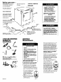
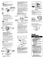
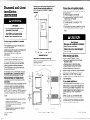
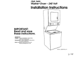
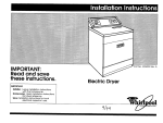
Part No. 9830492
IMPORTANT:
Read and save
these instructions.
IMPORTANT:
Installer: Leave Installation
Instructions
with the homeowner.
Homeowner: Keep Installation Instructions
for future reference.
Save Installation Instructions for local
electrical inspector’s use.
-I
Compact
240~Volt
Dryer
Before you start...
Check location where dryer will
Open dryer and remove
literature and parts
packages.
be installed. Proper installation is
your responsibility.
Make sure
you have everything
necessary
for correct installation,
Grounded electrical
Important: Observe all
governing codes and
ordinances.
supply
is required. See Electrical
requirements,
Panel A.
Four-inch metal exhaust
duct is required.
Check code requirements:
Some codes do not permit or
limit installation of clothes
dryers in garages, closets,
mobile homes, or sleeping
quarters. Contact your local
building inspector.
Electrical Shock Hazard
It is the customer’s responsibility:
9 To contact a qualified electrical
installer.
. To assure that the electrical
installation is adequate and in
conformance with National
Electrical Code, ANSI/NFPA 704atest
edition*, and all local codes and
ordinances.
Failure to do so could result in fire,
electrical shock or other personal
injury.
Fire Hazard
. Do Not store gasoline, paint thinners,
or other flammable materials near
dryer. Fumes from such materials
may result in fire or explosion.
Never install dryer up against
draperies or curtains or on carpet.
Keep any and all items from falling
or collecting behind the dryer.
Failure to follow these instructions
could result in a fire or explosion.
l
l
Protection from the weather:
Proper operation
of dryer cycles
requires temperatures
above 45”F,
or the dryer may not shut off when
automatic
cycles are used.
level floor: 1-inch maximum
slope
under entire dryer.
closet installation
instructions” on back cover.
Support: Floor must be
sturdy enough to support
dryer weight of 92 pounds.
Tools and materials
needed for
installation:
Fire Hazard
If you install the dryer in a garage,
carport, or areas near vehicles where
fumes from gasoline or other flammable
materials may be present, the vapors
may be heavier than air and remain near
floor. Place dryer a minimum of 18 inches
above floor. Check with your building
inspector regarding requirements for this
installation.
Failure to follow these instructions could
result in fire or explosion.
Electrical
Requirements
This appliance
is manufactured
with the
neutral terminal connected
to the cabinet
Electrical Shock Hazard
Electrical ground is required on this
appliance.
If cold water pipe is interrupted by
plastic, non-metallic gaskets or other
insulating materials, Do Not use for
grounding.
Do Not ground to a gas pipe.
Do Not modify the power supply cord
plug. If it does not fit the outlet, have a
proper outlet installed by a qualified
electrician.
Do Not have a fuse in the neutral or
grounding circuit. A fuse in the neutral
or grounding circuit could result in an
electrical shock.
Do Not use an extension cord with this
appliance.
Check with a qualified electrician if
you are in doubt as to whether the
appliance is properly grounded.
Failure to follow these instructions could
result in serious injury or death.
l
l
4. The appliance
may be connected
directly to the fused disconnect
or circuit
breaker box through flexible armored or
non-metallic
sheathed copper cable.
Allow two or three feet of slack in the line
between the wall and the appliance
so
that it can be moved if servicing is ever
necessary. A 3/4”, U.L.-listed strain relief
must be provided at each end of the
power supply cable (at the appliance
and
at the junction box). Wire sizes (COPPER
WIRE ONLY) and connections
must
conform with the rating of the appliance
(30 amperes).
l
l
knife
l
Parts supplied for
installation:
Remove parts from packages.
Check thal
all parts were included.
l
l
If codes permit and a separate grounding
wire is used, it is recommended that a
qualified electrician determine that the
grounding path is adequate.
1. A three-wire or four-wire, single-phase,
literature
Panel A
package
120/240-volt, 60-Hz, AC only, electrical
supply (or three-wire or four-wire,
120/2O&volt if specified on nameplate)
is
required on a separate 30-ampere
circuit,
fused on both sides of the line. Time-delay
fuse or circuit breaker is recommended.
2. This dryer is equipped
with a
3-wire
30-amp-rated,
flexible-type,
receptacle
(IOdOR)
power supply cord (pigtail).
Where local codes permit, it
must be plugged into a
mating, 30-amp receptacle
(NEMA Type 1O-30R). (See
Figure 1.)
3. IF THE POWER SUPPLY CORD IS
REMOVED, THE DRYER MUST BE
CONNECTED WITH lo-GAUGE
COPPER WIRE ONLY.
Figure 1
IMPORTANT: OBSERVEALL GOVERNING
CODES AND ORDINANCES.
5. For mobile home or other four-wire
installations, the 3-wire power supply cord
must be removed and the appliance
wiring must be revised. The appliance
cabinet must not be connected
to the
neutral terminal, but must be connected
to the grounding wire (green with yellow
stripes) of the power supply cord or cable.
(See Panel B for details.)
When a four-wire receptacle
of NEMA
Type 14-30R is used (See Figure 2), a
matching
120/240-volt
I-wire
minimum, 30-ampere,
ULrT:?$&r
listed dryer power supply cord
(pigtail) must be used. This
cord contains four No.-10
copper conductors
with ring
terminals or spade terminals
with upturned ends on dryer
end terminating
in a NEMA
Type 14-30P plug on supply
end. The fourth (grounding)
conductor
must be identified
by a green or green/yellow
Figure 2
cover and the neutral
conductor
by a white cover. Cord should
be Type SRD or SRDT, with a 3/4”, U.L.-listed
strain relief and be at least four feet long.
The power supply cord kit and strain relief
are not provided with the dryer.
Alternate electrical
connection
When local codes...
A
Permit use of a flexible type power
w
supply cord (pigtail) that comes equipped
with the dryer but
Do Not Permit connecting
the cabinetgrounding
conductor
to the neutral wire of
the power supply cord:
Connect
separate
center
neutral
(center
wire of
pigtail)
”
Ungrounded
silver-
neutral
Mobile home or other four-wire
installation
Figure 3
Requires a four-wire
cable.
1. Disconnect the power supply.
2. Remove terminal block cover.
3. Remove the grounding wire (green) from
the internal grounding connector
and
fasten under center, silver-colored
terminal block screw. See Figure 3.
4. Connect a separate copper grounding
wire (No.-10 minimum). See ‘To connect a
separate grounding wire,” Panel B for
detailed instructions.
5. Replace the terminal block cover.
external grounding
connector
_
B
n
eutral
wire of the
external gr
connector
center silvercolored
terminal block
screw
Grounded neutral
Figure 4
1. Disconnect the power supply.
2. Remove the power cord equipped
with
the dryer as instructed. See ‘To remove
the power supply cord,” Panel B.
3. Prepare wire ends. See “Direct wiring
connection,”
Panel B.
4. Install copper power supply cable through
3/4”, U.L.-listed strain relief. Tighten strain
relief to cabinet.
5. Connect the white (neutral) wire of the
flexible armored or non-metallic
sheathed
copper power supply cable to the center,
silver-colored
terminal screw of the
terminal block. Connect the other wires to
the outer terminals. See Figure 4.
6. Tighten strain relief clamp screws. Replace
the terminal block cover.
onnection
or
center wire or
j pigtail)
2. Remove the power supply cord equipped
with the dryer as instructed. See Panel B,
‘To remove the power supply cord.”
3. If using direct wiring, see “Direct wiring
connection,
Panel B.
4. Install copper, four-wire, power supply
cord or cable through a 3/4”, U.L.-listed
strain relief or conduit connector.
Tighten
strain relief to cabinet.
5. Remove the grounding wire (green) from
the internal grounding
connector
and
fasten under center, silver-colored
terminal block screw.
6. Connect the grounding wire (green) of
the copper 4-wire power supply cord to
the internal grounding
connector.
7. Connect the neutral (white wire of direct
wiring connection
or center wire of pigtail)
to the center, silver-colored
terminal screw
of the terminal block. Connect the other
wires to the outer terminals, See Figure 6.
8. Tighten strain relief clamp screws. Replace
the terminal block cover.
To connect
wire:
Use grounding wire and clamp assembly
(Part No. 685463) or No. 10 gauge minimum
copper grounding wire.
Tighten clamp
securely to pipe.
Bumps on ground strap
must contact pipe.
with the dryer
Permit copper power supply cable and
Do Not Permit connecting
the cabinetconductor
to the neutral
supply cable:
Connect separate copper grounding
from external grounding connector
approved
ground.
/
wire of
cold metal
water pipe
wire
to
aroundina
center
white
(neutralr
wire
1. Disconnect the power supply.
Panel B
silver-
’
clamp;
Figure 7
Connect grounding wire to a grounded
cold water pipe* with the clamp and then
to the external grounding connector on the
dryer. See Figure 7. Do Not ground to a gas
supply pipe or hot water pipe. Do Not
connect the power supply cord to electric
power supply until the appliance
is
permanently
grounded.
* Grounded
cold water pipe must have metal contrnuity
to electrical
ground and not be Interrupted
by plastic,
rubber or other electrical
insulating connectors
such as
hoses, fittings, washers or gaskets (including water
meter or pump) Any electrical
insulating connector
should be jumped as shown in Figure 7 with a length of
No.-4 wire securely clamped
to bare metal at both
ends.
Ungrounded neutral
Figure 5
w
1.
Figure 8
1. Disconnect the power supply.
2. Remove the terminal block cover from the
dryer.
3. Disconnect
the power supply cord from
the terminal block.
4. Use a screwdriver to slide the strain relief
clip away from the power supply cord.
(See Figure 8).
5. Pull downward
on the power supply cord
until it is removed from the dryer. (See
Figure 8).
To use nonmetallic sheathed
copper power
supply cable :
Figure 9
If non-metallic
sheathed
copper power supply cable
is used, it must be used with a 3/4”, U.L.-listed
strain relief to fit a one-inch hole size similar to
the one shown in Figure 9.
Direct wiring connection
1. Strip outer covering
back 3 inches from
the end exposing the 3 wires.
2. Strip the insulation back 1 inch from the
end of each wire. Form the bare wire into
a ‘U” shaped hook.
-1
P
Figure 10
a separate grounding
w Do Not Permit the use of the flexible
grounding
the power
Pa
COI
Exhaust
requirements
When local codes...
external
(white wire
1. Disconnect the power supply.
Do Not Permit the use of the flexible
supply cord equipped
with the dryer
supply cord equipped
Pull out power
supply cord.
harness grounding
wire (green)
-- j
Figi*
conductor
to the white (neutral)
power supply cable:
C
supply cord or
power supply c
grounding
wire(green/yellow)
Permit copper power supply cable and
Permit connecting
cabinet-grounding
power
and
power
To remove the power supply cord
center silver$ colored terminal
When local codes...
power
and
2. Remove the power supply cord equipped
with the dryer as instructed. See “To
remove the power supply cord,” Panel B.
3. Prepare wire ends. See “Direct wiring
connection.”
Panel B.
4. Install copper power supply cable through
3/4”, U.L.-listed strain relief. Tighten strain
relief to cabinet.
5. Remove the grounding wire (green) from
the Internal grounding
connector
and
fasten under center, silver-colored
terminal
block screw.
6. Connect the white (neutral) wire of the
flexible armored or non-metallic
sheathed
copper power supply cable to the center,
silver-colored
terminal screw of the
terminal block. Connect the other wires to
the outer terminals. See Figure 5.
7. Connect a separate copper grounding
wire (No.-10 minimum). See ‘To connect a
separate grounding wire,” Panel B, for
detailed instructions,
8. Tighten strain relief clamp screws. Replace
the terminal block cover.
Fire/Health Hazard
Do Not use non-metal, flexible duct.
9 Do Not use metal duct smaller than
four inches in diameter.
. Do Not use exhaust hoods with
magnetic latches.
9 Check that exhaust system is not
longer than specified. Exhaust systems
longer than specified will:
- Accumulate lint.
- Shorten the life of the dryer.
- Reduce performance, resulting in
longer drying times and increased
energy usage.
Failure to follow specifications may
result in a fire.
. Do Not exhaust dryer into a chimney,
furnace cold air duct, attic or crawl
space, or any other duct used for
venting.
9 Clean the exhaust system every other
year.
Do Not install flexible duct in enclosed
walls, ceilings or floors.
Accumulated lint could result in a fire or
cause moisture damage.
. Exhausting your dryer indoors is Not
recommended. The moisture and lint
indoors may cause:
- FIREHAZARD from lint collected in
dryer;
- Moisture damage to woodwork,
furniture, paint, wallpaper, carpet,
etc.
- Housecleaning problems and
possible health problems.
Failure to follow these instructions could
result in fire damage or personal injury.
l
l
Mobile home exhaust
requirements: The dryer must
Use duct tape to seal all joints.
Four-inch rigid metal pipe is
preferred. Plan installation to
use the fewest number of elbows
better
n
and turns
i==l
Metal flexible duct must be fully extended
and supported
when the dryer is in its final
position. DO NOT KINK OR CRUSH THE DUCT.
The metal flexible duct must be completely
open to allow adequate
exhaust air to flow.
Allow as much room as possible when using
elbows or making turns. Bend duct gradually
to avoid kinking. Remove excess flexible
duct to avoid sagging and
kinking that may result in
reduced air flow.
Exhaust Outlet is located at
the center of the bottom
dryer back.
The exhaust duct can be
routed up, down, left, right
or straight out the back of
the dryer. Detailed space
requirements
are provided
on the back cover of
Installation Instructions.
Maximum length of the exhaust system
depends upon the type of duct used,
number of elbows and the type of exhaust
hood. The maximum length for both rigid
and flexible duct is shown in chart.
l-
EXHA
I HOOD TY
have an outside exhaust. If the
dryer is exhausted through the
floor and the area under the
mobile home is enclosed, the
exhaust system must terminate
outside the enclosed area.
Extension beyond the
enclosure wili prevent lint and
moisture buildup under the mobile
6
n
Move the drver to its oermanent
location. Remove cardboard
‘or hardboard
from under dryer. Check levelness of dryer
by placing
level on top of the dryer, first side
to side, then front to back. If dryer is not
level, adjust the legs of the dryer up or down
until dryer is level.
area.
Remove the tape that holds the
1 n
drum to the cabinet. (Some dryer drums are
not taped for shipping.) Move the drum by
hand to make certain all tape has been
removed. Wipe the interior of the drum
thoroughly with a damp cloth before using
the dryer. Remove tape from lint screen.
Al FI.
33 Fr.
31 FT.
23 Fr
21 Fr
30 Fr.
29 FT.
2AFT.
23 FT.
16FI.
15 FT.
3
by the
with your dealer
exhaust length chart, check
or distributor for information.
Service check: The back pressure in any
exhaust system used must not exceed 0.3
inches of water column measured with an
inclined manometer
at the point that the
exhaust duct connects to the dryer.
Exhausting the dryer outside is
recommended.
A closet installation must be
exhausted
outside. Recessed installation
that is not exhausted
outside must use
Exhaust Deflector Part No. 603197 available
from your dealer. See “Recessed and closet
installation instructions” on back cover for
adequate
unobstructed
air opening
requirements.
If the dryer is installed in a confined area
such as a bedroom, bathroom, or closet, it
must be exhausted to the outside and
provision must be made for enough air for
combustion
and ventilation.
Check
governing
codes and ordinances.
Also refer
to the “Recessed and closet installation
instructions” on back cover.
An exhaust hood should cap
the exhaust duct to prevent
exhausted air from returning
into dryer. The outlet of the
hood must be at least 12”
from the ground or any
object that may be in the
path of the exhaust.
Four-inch outlet exhaust
hood is preferred. However,
1 n To exhaust the dryer, see Exhaust
requirements.
Connect exhaust duct to
exhaust hood. Use duct tape to seal all joints
in exhaust duct. Use caulking compound
to
seal exterior wall opening around exhaust
hood.
n Carefully push
8
timer knob on the
timer shaft at the front
of the dryer.
Stand in front of dryer. Firmlv grasp
the body of the dryer and gently lay ti right
side down on the cardboard
corners.
For exhaust systems not covered
7
&
n Take two of the cardboard
corners
from the carton and place them on the floor
to the right side of the dryer.
A3 Fr.
n Now stand the dryer up.
home.
Now start...
with dryer in laundry
5
re
2
NUMBER OF
90” TURNS
n
7
”
I
timer knob
9
n Check to see that all of the parts you
removed from the installation parts
packages
are now installed in the dryer. If
you still have an extra part, go back through
the steps to see what you skipped. Check to
make sure you have all the tools you started
with.
10
n Plug the
electrical
cord into
the grounded
outlet.
4
n Start to
screw the legs into
the holes bv hand.
Use a small’amount
of liquid detergent
to
lubricate the screw so it is easier to turn the
leg. Use an adjustable
wrench to finish
turning the legs until you have 1” of the leg
below the base.
11
n Read the Use and Care Guide to
fully understand
you new dryer. Start the
dryer. Start the dryer and allow it to
complete
a regular cycle. After five minutes,
open dryer door and check that dryer is
operating
properly.
To get the most efficient use from
your new dryer, read your Use
and Care Guide. Keep Installation
Instructions and Guide close to
the dryer for easy reference.
Floor Damage
Slide dryer onto cardboard or hardboard
before moving across floor.
Failure to do so may cause damage to
floor covering.
J
8.
6.
0
3
_
I
3L
a 2-l/2-inch
outlet exhaust hood may be
used. A 2-l/2-inch
outlet exhaust hood
creates greater back pressure than other
hood types.
For permanent installation, a stationary
exhaust system is required.
Mobile home installation
This appliance
is suitable for mobile home
installations. The installation of the dryer must
conform to the Manufactured
Home
Construction
and Safety Standard, Title 24
CFR, Part 3280 (formerly the Federal
Standard for Mobile Homes Construction
and Safety, Title 24, HUD Part 280, 1975) or
the latest edition.
Panel C
ide
Numbers
correspond to
steps.
Recessed and closet
installation
instructions
Recessed non-exhausted installation must
use only the rear exhaust position and
Exhaust Deflector Kit, Part No. 346001 is
required.
Fire Hazard
. It is recommended that the dryer be
exhausted to the outside.
If the dryer is installed in a closet, the
dryer MUST be exhausted outside.
Failure to do so may result in a fire.
If dryer does not operate properly...
If dryer will not operate, check the following
to be sure that:
A. Electrical supply is connected.
B. House fuse is intact and tight or circuit
breaker has not tripped..
C. Door is closed.
D. Controls are set in a running or “On”
position.
E. Start button has been pushed firmly or the
power control lever moved upward to
start.
dryer
l
The dryer may be installed in a recessed
area or closet.
The installation spacing is in inches and is
minimum allowable.
Additional
spacing should be considered
for
ease of installation, servicing and
compliance
with local codes and
ordinances.
If closet door is installed, the minimum
unobstructed
air openings in top and
bottom is required. Louvered doors with
equivalent
air openings are acceptable.
Closet installation must be exhausted.
Other installations must use the minimum
dimensions indicated.
uasher
Recessed
Floor Damage
Slide dryer onto cardboard or hardboard
before moving across floor.
Failure to do so may cause damage to
floor covering.
iron+ view
When moving your dryer...
Minimum installation spacing
all
closei
TO PREVENTLARGE AMOUNTS OF LINT AND
MOISTUREFROM ACCUMULATING AND TO
MAINTAIN DRYING EFFICIENCY AND TO
PREVENTEXPOSURETO POSSIBLEHEALTH
HAZARDS, THIS DRYERMUST BE EXHAUSTED
OUTDOORS.
Part No. 9830492
01992
l
If you need assistance...
Check your Use and Care Guide for a tollfree number to call or call the dealer from
whom you purchased
this appliance.
The
dealer is listed in the Yellow Pages of your
phone directory under ‘Appliances
Major.”
When you call, you will need the dryer
model number and serial number. Both
numbers are on the nameplate
located in
the door well behind dryer door.
This compact
dryer may be installed with the
compact
washer companion
appliance
using one of the Stack Stand Kits, Part No.
695570,3390175
(white) or 3390196 (almond).
The electric dryer may also use Wall Mount
Kit, Part No. 345994. Do Not use in mobile
home.
a Additional
clearances
for wall, door and floor
moldings may be required.
** Opening is minimum for closet door. Louvered
door with equivalent
air openings is
acceptable.
**’ Additional
space is needed when external
exhaust elbow IS used.
Shut off electric supply to dryer.
Disconnect
electrical cord and tape
securely to dryer.
l
Tape the drum to the front panel.
l
Tape the dryer door and lint screen.
l
Screw leveling legs all the way in.
Before having your electric dryer installed in
your new home, check with a licensed
electrician
to confirm that the supply
voltage matches the voltage specified on
that nameplate.
l
Note: If recessed installation is exhausted,
spacing can be 0”.
Closet installation must be exhausted.
Front View
Side View
Benton
Harbor,
Michigan
49022
Printed in Canada