1
192 CHANNEL DMX OPERATOR
USER MA NUAL
CAUT IO N I
Keep this device away from rain and moisture!
Unplug mains lead before opening the housing!
For your own safety, please read this user manual carefully before your initially start-up!
Every person in volved wllh Ihe installation. opera1ion and maintenance of this device has to
• be qualified
• followlhe instructions of th is manual
- consider this manual 10 be pari of the total product
- kellp this manual lor the entire service life oflhe product
- pass th i s manual on to avery further owner or user of the product
- include every supplementary update wilh Ihe original manual
Before your initi31 start-up, please make sure that Ihere is no damage caused during shipment. Should there be
eny, do not use the device and consult your supplier.
SAFETY INSTRUCTIONS
This device has left our premises in absolutely perfe ct condition. In ordor to maintain this condition and to en·
sure a safe operation, it is absolutely necessary for the user to follow the safety instructions and warning notes
written in this user manual.
Impor tant: Damages caused by the disregard or thiS user manual are not subject to warranty. The
dealer will not accept liability for any resulling defects or problems.
Always plug in the power unit least.
Keep away from heaters and other heating sources I
Keep away children and amateurs from the device! Never leave the device running unatlended!
If th e d evice has been e~posed to drastic temperature fluctuation (e.g. after transportat ion). do not switch it on
immediataly. The arising condensation water might damage your device. Leave the device switched off until it
has reached room temperature.
This device falls under protection·class III. It always has to be operated with an appropriate trans former. Check
the device, the power cord and transformer from l ime to lime. Make sure thet the transformer Is the correct type
as that slaled on the rear panel.
Always disconnect from the mains, when the device is not in use or before cleaning it
There are no serviceable parts inside the device . Maintenance and service operations ara only to ba carried
out by authorized dealers.
Plaase note that damages caused by manual modifications on the device or unauthorized operetion by unQualified persons are not subject to warranty.
OPERATING DETERMINATIONS
ThiS device is a DMX·controlier for controlling DMX-effects or spots in discotheQues. onstages etc. It is allowed
to be operated with a direct voltage olDC 9-12 V, minimum JOO mAand was designed for indoor use only.
00 not shake the device. Avoid brute force when installing or operating the device.
When choosing the installation-spot, plasse make sure that the device Is not e~posed to extreme heat, moisture
or dust. There should not be any cables lying around. You endanger your own and the safetyol others I
-1-
I
Operate the device only after having familiarized with its functions. 00 not permit operation by persons not qua lified for operatmg the device. Most damages are the result of unprofessional operationl
Please use the original packaging ilthe device
IS
to be transported
Please consider that unauthorized modlficetions on the device are forbidden due to safety reasons!
I!this device will be opera led in any way different to the one described in this manual, it may suffer damages and
the guarantee becomes void Furthermore. any other oparation may lead to dangers like short-circuit, burns.
electnc shock, etc.
MAIN FEATURES
Compact DMX controller
192 control channel for 12 projectors each up to 16 channels
6 chasers with up to 240 scenes can be programmed
30 banks 018 preset scenes, 240 scenes max.
Sliders reversible
Channels fe-assignable
Fog machine and strob e conlrol bullon
Grab any fixture on fly
Copy function for the scenes, programs and records
Blackout function
Beat aclivialion, lap sync and aula run
Sound conlrol via built-in microphone or Audio input socket
Polarity selector
MIDI compatible
19 inch mounting dimension (3 units)
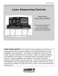
FRONT PANEL
,
..•.... ...
...,. .. •
2
7
9
13 t4 1516 20
. ·0. .. ,\.. ~ I.?:_-~"':~ ~iiii::= ~!;7
/
F~T7:'
,
,
,
,.
·
rn[ill£ITl@]@)!ID[![m:
•
.!..,~
::::.
. ". ..
o
,~
,.
6
5
11
"0
12
1718t921
REAR PANEL
(Q)
, Gro""c
25';""1('1
3S,g"0""1
MI 'IIN
"
~
,-@l
9
11~
[)C
Q
23
"
m
POWER SWITCH
DM10UT
25
26
- 2-
t
27
28
1. FIXTURES SELECT BUTTONS choose desired projector
2. FIXTURES INDICATOR LEOS
3. SCENE SelECT BUTTONS choose desired scene
4. CHANNEL FADERS fo adjusting OMX values. Ch 1-8 can be adjusted directly after pressing the respective
FIXTtJRES select button . Ch 9-16 can be adjusled after pressing the page select button
5. R & C I FADE BUTTON
6. FOG MACHINE BUTTON 10 activate tha fog machlna
7. PAGE AI PAGE B INOICATOR LED
8. STROBE BUTTON
9. DISPLAY WINDOW
10. PAGE SelECT BUTTON In manual mode , you can switch the faders from Ch 1-8 to Ch 9-16 by pressing
this button
11. SPEED FADER
12. FADE TIME FADER
13. BANK UP BUTTON
14. BANK DOWN BUTTON
15. PROGRAM BUTTON
16. MIDI I ADD BUTTON
17. AUTO I DEL BUTTON when you press this button , the Auto Trigger LED in bottom right corner of the Display
window will be lit. The controller is in Auto mode (operation with a programed bank)
18. MUSIC I BAN K COPY BUTTON when you press this button, the Music Trigger LE D in top right corner of the
Displaywindow will be lit . The controller is In Audio mode (operation with sound control)
19. TAP SYNC I DISPLAY BUTTON you can switch the display of the faderway from DMX-value (0-255) to
parcent (0-1 00).
20. CHASER BUTTONS
21 . BLACKOUT BUTTON to close the light output of all connected projectors via the schutter
22. MIDI input socket
23. DMX POLARITY selector
24 . DMX output socket
25. Power supply (DC 9-12V 300mA) locket
26. Strobe input socket
27 . Power switch
28 . Fog machine Input socket
29
31
30
Ste ITime
I
Music Trigger
Blackout
32 -
- - - 8 tep-f{)
Program
'-t-;:;;±±,-,-I-:o-:--c--t-t-'
33 34 35
36
Auto Trigger
37
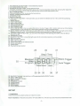
29 . BLACKOUT indicator cqn be lit on or off by pressirlQ the BLACKOUT button
30. STEP 'TiME display
31 . MUSIC TRIGGER indicator
32 . STEP Indicator
33. PROGRAM Indicator
34. CHASE display
35. SCENE display
36. BANK display
37 . AUTO TRIGGER Indicator
SETUP
1. lnst.".tlon
Install the device on a plane surface or install it in a fack.
Rack·l nstallatlon : This device Is built for 19" racks (483 mm). The rack you use should be a double-doof-rack
·3·
where you can open the front panel and the rear panel. The rack should be provided with a cooling fan . When
mounting the device into the rack, please make sure that there is enough space around the device so that the
hot air can be passed on . Steady overheating will damage your device . You can fix the controller with four
screws M6 in the rack .
Connect the connection cable of the power-un it with the DC IN-socket. Plug the power unit into your outlet.
2. Sound-control
The sound-control works via the built-in microphone .
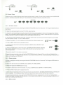
3. DMX 512 Connection with the projectors
Only use a stereo shielded cable and 3-pin XLR-plugs and connectors in order to connect the controller with the
fixture or one fixture with another.
The wires must not come into contact with each other, otherwise
the fixtures will not work at all, or will not work properly.
Occupation olthe XLR-connection:
You can adjust the XLR polarity via the DMX POLARITY selector.
Building a serial DMX-chain:
Connect the DMX-output 01 the device with the DMX-input 01 the nearest projector. Always connect one output
with the input of the next fixture until all fixtures are connected .
Caution: At the last fixture, the DMX-cable has to be terminated with a terminator. Solder a 1200him resistor
between Signal (- ) and Signal (+) Into a 3-pin XLR-p lug and plug It in the DMX-output olthe last lixture .
n
n
o
aononnoo
co
•
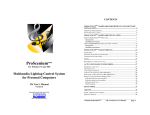
Projector addressing
Please note that the DMX Operator assigns the DMX-starting addresses every 16 steps .
You have to addres s every prolector to the respective starting address . Otherwise , the channel assignment will
not be correct.
All projectors with the same starting address work synchronically.
Projector
Projector 1
Starting
Address
1
Projector
Starting
Address
1
Projector 2
17
DIP Switch
DIP Switch
1. 5
ProJector 3
33
1. 6
Projector 4
49
1,5 . 6
Projector 5
65
1,7
Projector 6
61
1.5.7
Projector 7
97
1, 6, 7
Projector 8
113
1.5.6.7
Projector 9
129
1,6
Projector 10
145
1,5.6
Projector 11
161
1.6.6
Projector 12
177
1.5.6,6
-4-
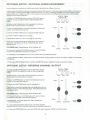
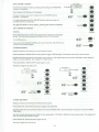
OPTIONA L SETUP: PHYSICAL FADER ASSIGNMENT
Use this featu re to combine or unify fixture conlrolattributes for different fixtures .
E.g tfyou are controlling 4 mo .... ing head spots, and 4 small scanners. The color, gebo. strobe effect , etc, may nol
line up ideally on the physical faders . Use th is function, you may re-asslgns the DMX channels of effect of color,
gobo. strobe, etc , to fader 1, 2 and 3. From now on , you may contro l the ditfernet l illtures with the same faders
location for the same attributes.
STEPiTlME
=
n,n2
IU
A. Press the PROGRAM button and the TAPSYNC button
togelheronce 10 access the mode of fader assignment
mode.
U
B. Select a FIXTURES bulton thai represents the fixture
whose faders you would like to re-asslgn .
C. Move the SPEED fader untillhe lEO display shows the
number of the controller channel .
O.lSEC
305
'rogf .... .
. .1Ii/Md.
D. Move the FADE TIME fader to select Ihe DMX channel .
E. Press Ihe MIDII ADO bulton 10 save.
F. Repeallhe sleps C, 0 , E to ra-assign all channels.
If you wanl to copy Ihe physica l assignment of one fixture
to another, follow the nut steps . Otherwise golo step J
directly 10 elCil.
FIXTURES Co py ' copy Fixt ur e .1 to Fixture
10MIN
'2
r .... ,..." .
SPEEO
Oolpl.,
FAOE TIME
G. Press and hold the FIXTURES button #1, the FIXTURES
button #2 and the MIDI I ADO bulton together.
H. Release the FIXTURES button #1 , then release the FIXTURES button tl2 .
I. lastly release the MIDI I ADO bulton. AlilEDs will blink, showing IheFIXTURES#1 has been copied toFIXTURES#2
sucessful1y.
J. Press and PROGRAM button and the TAPSY NC button togethe r twice to exit this mode .
OPTIONAL SETUP: REVERSE CHANNEL OUTPUT
STE P /TIM E
=n, nl u
A. Press Ihe PROGRAM button and the TAPSYNC bulton
together TWICE to access Ihe mode of fader assignment
mode.
B. Select aFIXTURES button Ihat represents the filClure
c~...
U
111 - ' ''']
s.:.... l.nII
whose faders you would like to reverse .
C. Move the SPEED fader unlit the lEO display shows the
number of the controller channel.
o lSEC
. . . ..
305
I IloIi/_.
D. Move Ihe FADE TIME fader until N changes 10 Y.
If you wanl to copy the reversed channel assignment of one
fix ture to another, follow the next steps . Otherwise gala step
H directly to exit.
FIXTURES C OPYi c opy Fixture '1 to Fixture . 2
E. Press and hold the FIXTURES button #1 , the FIXTURES
button #2 and the MIDI / ADO bulton together.
10MIN
F. Release the FIXTURES button #', then release the
FIXTURES button #2 .
0
SPfEO
FAOETIME
G. lastly release the MIDI I ADD bullon . AlilEDs will blink,
showing theFIXTVRES #1 has been copied to FrXTuREs#2 sucessfully.
H. Press and PROGRAM bulton lind the TAPSYNC button together ONCE to exit this mode .
- 5-
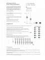
OPTIONAL SETUP:
FADE TIME ASSIGNMEN T
R- AI I ch ann els
Pa n / Ti lt only
p-
You can choose whether the board's fade time
during scene excution is implemented broadly
to all output channels or only to the PAN I TILT
movement channels . This is relevant because
sometimes you wil l want the gobos and the
colors to change Quickly while not affecting the
movement of the light.
t STEP/TIME
r:==:J
I R01:J 1
Ch...
Seen_
ee nk
A . Turn off t~ controller.
B Hold the BLACKOUT button and the TAPSYNC
button simultaneously.
O. 1SEC
305
C. Turn on the controller.
D. Press the TAPSYNC button to toggle between
the two modes . EitherA (All channels) or P (Pan I
Tilt only).
E. Press the BLACKOUT button and the
TAPSYNC button to save your setting .
All LEOs will blink to confirm your setting .
10MIN
OPERATION
SPEED
FADE TIME
After you connected the device lathe mains. the OMX Operator is ready for use .
1. Manual-mode: Call up proj ectors manually
tn the Manual-mode (Program-LED 011), you can call up the connected
projectors manually and control them via the CHANNEL FADERS . Please
note that adjusted settings cannot be memorized .
Select the desired projector via the Respect ive FIXTRRES se lect button .
Adjust the desired function via the channel faders .
P age Select- butto n :
Via the PAGE SELECT button (#10), you can adjust the channe l faders
from CH 1-8 to CH 9-16. When the LEDA is lit, you can program channel
1-8 . When the LED B is lit, you can program channel 9-16 .
•
..,. .7
.
.a
.
,. •
BIKkout
FIXTURES
..,. .'. 10..
••• ."
.
'"
••
,.
2. Pr ogrammIng
2.1. En tering / Exit t he pro g raming mode
Press and hold the PROGRAM-bulton for 3 seconds , until the Program-LED flashes in the display, at thelelt
bottom corner. This way you will enter the programing mode.
Press and hold the PROGRAM-button for 3 seconds again, until the Program-LED is off This way you will exit
the programing mode .
At this time, the BLACK-OUT LED will be lit, and the device is in BLACK-OUT mode . You can leave the BLACKI"\llTrnl'lnp hv nrR~!I; i na the BLACK -OUTbuttton .
8lackoUl@
Ta r~
~
•
I&'
•
81ackout
Program
2.2. Scene I Step
A secene (step)! s a stati c lighting state Secens can be stored in banks . On top of Ihe controller, there are B SCENE
buttons . A bank has Bscnens maximum The controller has 30 bank memones, 10lal240 scenes .
1&' -------SCE NES
2
3
•
•
2.2. 1, Create a scene
A . Enter the program mode by press ing and hold the PROGRAM bulton for 3 seconds. The Program-LEO flashes In
Ihe clisplay
B Select the desired projector vi a Ihe FIXTURES select buttons .
C . AdJust the desired settlngs(change the projector attributes such as gobos or colors) v ia the respective channel
faders . You may need 10 select channel9-16 by pressing the PAGE SELECT bullon . When the lE DA is lit, you can
program channelt-B. Whenlha LED B Is lit, you can programchanneI9-te .
D. To program another projector, press the FIXTURES select button you have just fin,shed programing , and select
the next projector via tha FIXTURES select buttons .
E . Repeal the steps B· D untit all projeclors of Ihe scene heve been programmed .
~Mld I/Add.
F. Press the MIDI/ ADD bulton to prepare to store
G . Choose a bank 10 store this scene by pressing the BANK buttons (BANK UP and
BANK DOWN).
H . Select 8 SC ENE button to slore th is scene . All LEOs will bllnlc 3 times, showing
the scene Is stored. In the display window it will show the bank and scene number
that is programmed .
••
Bank
.~
I. Repeat the steps B· H to create more scenes.
To leave the program mode, press and hold the PROGRAM button for 3 second .The controller w ill default to the
BLACK·OUT mode The black·out LED will be III. You can leave Ihe BLACK·OUT mode by pressi ng the BLACK-OUT
buttton until the black·out LED be orf.
2.2.2. Copy a scene
A. Enter the program mode by pressing and hold the PROGRAM bulton for 3 seconds. The Program-LED flashes in
the display.
B. Select the desire d bank via the BANK buttons (BANK UP I BANK DOWN) .
C. Press the respective SC ENE button to copy.
D. locale Ihe destination scene in the bank. You m.y use BANK buttons (BANK UP I BANK DOWN).
E. Press the MIDI I ADD button to prepare 10 store.
F. Select the desired SCENE button where you waniio copy Ihe scene to. All LEOs wilt blink 3 times, showIng the
scene I. copied. In the display window 11 will show the bank and scene number Ihal has been copied to.
To leave Ihe program mode . press and hold the PROGRAM button for 3 second . The controller will default 10 the
BLACK·OUT mode The black·out LEO will be lit . You can leave the BLACK-OUT mode by pressing the BLACK·OUT
bUllion until the black-out LED be off
2.2.3. Edit a scene
A. Enter the program mode by pressing and hold the PROGRAM button for 3 seconds. The Program-LED flashes in
the display.
B. Select the desired bank via the BANK buttons (BANK UP I BANK DOWN) .
C. Press the respective SCENE button to edit.
D. Adjust the desired seWngs(change the projector attributes such as gobos or colors) via the respective channel
faders . You may need to select channel 9-16 by pressing the PAGE SELECT button . When the LED A is lit. you can
program channeI1-B . When the LED B is lit. you can program channel 9-16 .
E. Press the MIDII ADD button to prepare to store .
F. Select the SCENE button you previously selected again . All LEOs will blink 3 times, showing theseenels edited.
In the display window it will show the bank and scene number that has been edited .
To leave the program mode . press and hold the PROGRAM button for 3 second . The controller will default to the
BLACK-OUT mode . The black-out LED will be lit. You can leave the BLACK-OUT mode by pressing the BLACK-OUT
buttlon until the black-out LED be off.
2.2.4. Delete a scene
A. Enter the program mode by pressing and hold the PROGRAM button for 3 seconds . The Program-LED flashes in
the display.
B. Select the desired bank via the BANK buttons (BANK UP I BANK DOWN) .
~
C. Press the respective SCENE button to delete .
Auto/Dele
D. Press and hold theAUTOI DEL button to prepare to delete.
F. Select the SCENE button you previously selected again . All LEOs will blink 3 times, showing thescene Is deleted. In the display window it will show the bank and scene number that has been deleted .
The result of deleting a scene is actually a value reset to 0 of the DM X- value of the scene selected . The physicallocation of the scene remains .
To leave the program mode. press and hold the PROGRAM button for 3 second .The controller will default to the
BLACK-OUT mode . The black-out LED will be lit. You can leave the BLACK-OUT mode by pressing the BLACK-OUT
buttton untilthe black-out LED be off.
2.2.5. Delele al/ scenes
Caution : When you select this function . all programmed scenes will be irrevocably lost!
A. Press and hold the PROGRAM button and the BANK DOWN button while disconnecting the device from the mains .
B. Connect th e device to the mains again .
All scenes has been deleted .
2.3. Bank / Program
A bank (program) is a sequence of different scenes that will
be called up one after another.
I~ .
With this DMX Operator. you can program up to 30 different
banks with up to B scenes each .
:0:
1':1
~
e·
eT
Bank
~
The bank number will be shown in the last two digits in the display window wh ile you press the BANK buttons (BANK
UP I BANK DOWN) .
2.3.1. Creale a bank
A. Enter the program mode by pressing and holding the PROGRAM button for 3 seconds . The Program-LED flashes
in the display.
B. Select the desired bank via the BANK buttons (BANK UP I BANK DOWN).
C. Select the desired projector via the FIXTURES select buttons . The respective LED will be lit.
D. Adjust the desired settings(change the projector attributes such as gobos or colors) via the respective channel
faders. You may need to select channel 9-16 by pressing the PAGE SELECT button . When the LEDA is lit, you can
program channeI1-B. When the LED B is lit. you can program channel 9-16.
-B-
I.
..
E. Press the FIXTURES select button you have just finished programing (so thallhe respective LEO if off).
F. To program another projector, repeat the steps C - E until all projectors of the scene have been programmed.
G . Press the MIDII ADO button to prepare to store.
H. Press the respechve SCENE button in order to save the first scene. All LEOs wfll blink 3 times, showing the
scene Is stored. In the display window it will show the bank and scene number that is programed.
I. Repeal the steps C - H to program the next scene until the maximum number of scenes - 8 - has been reached .
To leave the program mode. press and hold the PROGRAM bullon for 3 second.The controlier will default to the
BLACK-OUT mode. The black-out LED will be lit. You can leave the BLACK-OUT mode by pressing the BLACK-OUT
buttton until the black-out LED be off
2.3.2. Checking a bank
Enter programing mode by pressing and holding the PROGRAM button
Select the desired bank via the BANK buttons (BANK UP I BANK DOWN).
e ..
e ..
Check every scene individually by pressing the respective SCENE bulton.
2.3.3. Running a bank
Bank
Selecllhe desired bank via the BANK buttons (BANK UP I BANK DOWN).
Press the AUTO I Del button and the Auto Trigger LED is Illuminated in the display.
Adjust the program speed via the SPEED Fader and the repehl ,on rate via the
FADE TIME Fader.
As an alternative, you can adjust the program speed by tapping tha TAP SYNC I
DISPLAY button twice . The time interval between the two laps corresponds to the
program speed (up to 10 minutes).
~AU10/D.I .
~ TapSync .
~
Display
2.3 .•. Editing a bank
Should you notice that a scene does not correspond to your Imagination, or when programs have to be edited for 8
new stage, it is necessary to modify a scene manually
A. Enter the program mode by pressing and holding the PROGRAM button for 3 seconds. The Program-LED flashes
in the display.
B. Select the desired bank via the BANK buttons (BANK UP I BANK DOWN) .
C. Select the desired scene you want to edit via the SCENE button .
D. Select the desired projector you want to edit via the FIXTURES select buttons. he respective LED wil l be lit.
E. Adjust the desired selllngs(change the projector attributes such as gobos or colors) via the respective channel faders . You may need to select channel 9-16 by pressing the PAGE SELECT button . When the LED Ais lit, you can program channel 1-8. When the LED B is lit, you can program channelg-16.
F. Press the FIXTURES select button you have just finished editing (so that the respective LEO is oR).
G. To edit another projector. repeat the steps C - E until all projectors of the scene you want to edit have been edited.
G. Press the MIDI f ADD button to prepare to store you editing .
H. Press the respective SCENE button in order to save the edited scene. All LEOs will blink 3 ames, showing the
scene Is edited. In the display window it will show the bank and scene number that is edited.
I. Repeat the steps C· H to program the next scene until the program editing is finished.
To leave the program mode, press and hold the PROGRAM button for 3 second.The controller will default to the
BLACK-OUT mode. The black-out LED will be lit. You can leave the BLACK-OUT mode by pressing the BLACK-OUT
bultton untillhe black-out LED be off.
2.3.5. Copy a bank
A. Enter the program mode by pressing and holding the PROGRAM bullon fo r 3 seconds. The Program-LED flashes
In the display.
·9·
B. Select the desired bank you want to copy via the BANK buttons (BANK UP I BANK DOWN) .
C. Press the MIDII ADD button .
D. Select the desired bank where you wish to copy the bank to .
E. Press the MUSIC I BANK COPY button to cmplete your copy. All LEOs will blink 3 times, showing the bank Is
copied. In the display window it will show the bank and scene number that is programed .
To leave the program mode , press and hold the PROGRAM button for 3 second .The controller will default to the
BLACK-OUT mode . The black-out LED will be lit. You can leave the BLACK-OUT mode by pressing the BLACK-OUT
buttton until the black-out LED be off.
2,3,6, Delete a bank
A. Enter the program mode by pressing and holding the PROGRAM button for 3 seconds . The Program-LED flashes
in the display.
B. Select the desired bank you want to copy via the BANK buttons (BANK UP I BANK DOWN).
C. Press and hold the AUTO I DEL button .
D. Press the MUSIC I BANK COPY button to delete . All LEOs will blink 3 tlmes,showlng the bank Is deleted. In the
display window it will show the bank and scene number that is programed .
To leave the program mode, press and hold the PROGRAM button for 3 second.The controller will default to the
BLACK-OUT mode . The black-out LED will be lit . You can leave the BLACK-OUT mode by pressing the BLACK-OUT
bullton until the black-out LED be off.
2.4. Chaser
Achaser is a sequence of different programs that will be called up one after another.
With the DMX Operator, you can program up to 6
different chasers with up to 240 scenes each (30
banks of 8 scenes each) .
0
0
0
The chaser number will be shown in the first digit
of the LED display window when you press the respectiveCHASER button (Chaser 1 - Chaser 6).
••
••
••
1° lon° 1°0
I 10Uo I 0
Chaser 1
~
2.4.1. Insert a scene Into a chaser
Chaser 2
A. Enter the program mode by pressing and holding the PROGRAM button for
3 seconds. The Program-LED flashes in the display.
Chaser 3
B. Select the desired chaser via the CHASER buttons (Chaser 1 - Chaser 6).
Chaser 4
C. Select the desired bank via the BANK buttons (BANK UP I BANK DOWN).
D. Select the desired scene (already programed) that you want to insert to
via the SCENE button .
Chaser5
E. Press the MIDI I ADD button . All LEOs will blink 3 times, showing the scene
Is Inserted. In the display window it will show the bank and scene and chaser
number that is programed.
Chaser 6
F. Program the next scene until the bank is finished or the maximum number of scene - 8 - has been reached .
G. Program the next bank until the chaser is finished or the maximum number of bank - 30 - has been reached .
H. Press and hold the PROGRAM button in order to save the chaser.
To leave the program mode, press and hold the PROGRAM button for 3 second .The controller will default to the
BLACK-OUT mode . The black-out LED will be tit. You can leave the BLACK-OUT mode by pressing the BLACK-OUT
buttton until the black-out LED be off.
2.4.2. Copying a bank Into a chaser
As an alternative, you can copy a whole bank (with up to 8 scenes) into a chaser.
A. Enter the program mode by pressing and holding the PROGRAM button for 3
seconds . The Program-LED flashes in the display.
-10-
n->:s;::>
IRs3
MUSiC/ .
Bank Copy
B. Select Ihe desired chaser (that you want to copy the bank to) via the
CHASER buttons (Chaser 1 - Chaser 6).
C. Select the desired bank you want to copy via the BANK buttons (BANK UP I BANK DOWN).
D. Press the MUSIC I BANK COPY button and the MIDI I ADO bullon TOGETHER to copy. Alf LED. will "lfnk:J tIm ..,
showing the bank I. copIed to the ch ... r. tn the display window it will show the bank and scene and chaser number
that Is progr.med .
To leave the program mode, press and hold Iha PROGRAM button for 3 .econd .The controtterwill default to the
BLACK-OUT mode . The black-out LED will be lit. You clln leave the BLACK-OUT mode by pressing the BLACK-OUT
bullion unUI tha black-out LED be off.
2.4.3. Checking a chaser
Enter the program mode by pressing and holding Ihe PROGRAM button for 3 seconds . The Program-LED flashes In
the display.
Select Ihe desired chaser via the CHASER buttons (Chaser 1 - Cheser 6).
~TapsynCI .
~
Press the DISPLAY button In order to sw itch the display to step .
Display
Check every Icene individually by pressing the respective BANK buttons .
2.4.4. Running _ chuer
Press tha respective CHASER buttons (Chaser 1 - Chaser 6) end press the AUTO I DEL bullon .
You can adjust Ihe chaser speed by tapping the TAP SYNC I DISPLAY button tw ice . The time Interval between the 2
taps corresponds to Ihe chaser .peed (up to 10 minutes ).
Press Ihe MIDI I ADD button and select Ihe desired record via the SCANNER select buttons.
2.... 5. Edlllng a chaser
Insert a step
A. Enter the program mode by pressing and holding the PROGRAM button for 3 seconds .
STEPITIME
The Program-LED flashes in the display.
• 1"8"• I"n"·
leU ;
B. Select a desired chaser via the CHASER buttons
(Chaser 1 • Chuer 6).
Step; J
C. Press the TAP SYNC I DISPLAY button in order to Iwitch
the display to step .
D. Press the respective Bank-bullon in order to select the
scenewherelhe steps Is to be inserted .
~
E. Press the MIDII ADO button
Tap Sync I.
Display
F. Select the desired Icene via the BANK buttons and the respective SCENE button .
G. Press the MIDI I ADD button once more.
Delete a step
A. Enter the program mode by pressing and holding the PROGRAM button for 3 seconds .
The Program-LED flashes in the display.
B. Select a desired chaser via Ihe CHASER buttons (Chaser 1 - Chaser 8) .
C. Press the TAP SYNC I DISPLAY button In order to switch the LED display to steps .
D. Press the BANK UP or BANK DOWN button In order to select the scene whare the step Is to be deleted.
E. Press the AUTO I DELETE button to deletelhe step.
F. Press and hold the Program-button in orderto save the edited chaser.
-11 -
2.4.6. Delete a chaser
A. Enter the program mode by pressing and holding the PROGRAM
button for 3 seconds.
••
••
••
Chaser 1
The Program-LEE> flashes in the display.
Chaser 2
B. Select a chaser you want to delete via the CHASER button s
(Chaser 1 - Chaser 6) .
1&
program .
Chaser 3
C. Press and hold the AUTO I DELETE button and then press the
CHASER button you selected .
Chaser4
All LEDs wl/l blink for three times, showing the chaser Is deleted.
AutoIDel .
2.4.7. Delete all chasers
Chaser 5
Cauti on:
Chaser 6
When you select this function, all programmed chaser will irrevocably
be lost. The individual scenes and programs are still maintained .
e~
~
Turn off the device .
Press and hold the BANK DOWN button and the AUTO I DELETE button
and turn on the device again.
~
3. Sound-control
Bank
Auto/Del e
Select a Chaser by pressing one of the Chaser buttons .
Press the MUSIC I BANK COPY button (Music Trigger LED will blink) . The chaser will now run to the sound .
Please note that programs and records are only active in this mode when the controller receives a music-signal. If
there is no music present, the program or chaser stops .
Press the MUSIC I BANK COPY button again to exit.
The Music Trigger LED will be off.
~MUSiC
[=
J.D. JlITrigger
~
••
••
••
Chaser 2
Chaser 2
Chaser 3
Chaser 3
~Auto/Del .
Chaser4
MUSiC/ .
Chaser4
Chaser 5
Chaser 5
Bank-copy
••
••
••
Chaser 1
Chaser 1
Chaser 6
~ Tapsync,.
Chaser6
Display
4. Auto operation
Select a Chaser by pressing one of the Chaser buttons .
Press the AUTO I DELETE button (Auto Trigger LED will blink) .
You may adjust the time between steps by moving the SPEED fader and the duration of step by moving the FADE
TIME fader.
You can override the Speed and Fade Time by tapping the TAPSYNC I DISPLAY button three times. The chaser will
now run on the interval time of taps .
Press the AUTO I DELETE button again to exit.
The Auto Trigger LED will be off.
- 12 -
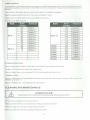
S. MIDI-op er ation
The controtlerwitl only respond to MIOI commands on the MIDI channel when it is set to fu ll stop_ All MIDI contrOl is
performed using Note on commands_ All other MIDI instructions are ignored To stop a chase, send the blackout on
the Note
Press the MIDI I ADO button and the third Bnd fourth digit in the display stertllashing
Select the respective MIDI-channel (1.16) to set via the BANK r'Jltons
Press and hold the MIDI I ADD button to store MIDI setup settings.
Overview on the MIDI·functlons
Bank
Bank 1
Bank 2
Notenumber
00
01
02
03
04
05
06
07
08
09
10
Function
Scene
Scene
Scene
Scene
Scene
Scene
Scene
Scene
Scene
Scene
Scene
Bank
1
2
3
4
5
6
7
8
1
2
3
Bank 15
Chase
Chase
Chase
Chase
Chase
Chase
Chase
...
Notenumber
112
113
114
115
116
117
118
119
120
121
122
123
124
125
126
Function
Scene 1
Scene 2
Scene 3
Scene 4
Scene 5
Scene 6
Scene 7
Scene 8
Chase 1
Chase 2
Chase 3
Chase 4
Chase 5
Chase 6
Blackout
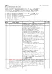
6. Fog m achin e co ntrol
Connect a fog machine (fogger) to the fogge r inpu t socket on the rear panel of the device.
The green LED shows the fog machine is ready to work
Press the Fogger·button when the green LED IS lit, the fog machine will start to work
7. Strob e con trol
Connect a flash strobe light to the strobe input socket on the rear panel of the device. The green LED on right of the
STROBE button will be lit
Press the STROBE button, the strobe light will start to work
CLEANING AND MAINTEN AN CE
DANGE R TO LIFEI
Disconnect from mains before starting maintenance operation!
We recommend a frequent cle9ning of the device
Please use a soft hnl-free and moistened cloth_ Never use alcohol or solvents!
Should you need any spare parts, please use genuine parts
Should you have further questions, please contact your dealer.
·13·
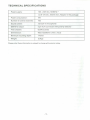
TECHNICAL SPECIFICATIONS
Power supply :
100 - 240V AC, 50/60Hz via 9-12V DC , 300mA min . Adaptor in the package
Power consumption:
4W
Number of control channels:
192
Sound control :
via built-in microphone
DMX 512 output:
3 pin XLR connector with polarity selector
Free chasers:
6x240 scenes
Dimmens ion:
482x132x80mm (19 in . X 3U)
Minimum mounting depth :
170mm
Weight:
2.5kgs
Please note: Every information is subject to change without prior notice .
-14-