1
OPERATOR'S MANUAL
&
INSTALLATION GUIDE
WESTERBEKE
15.0 BTD 60 - HERTZ
12.0 BTD 50 - HERTZ
MARINE DIESEL
GENERATOR SETS
SINGLE & THREE PHASE
Publication #36856
Edition Two
May 1995
j'-..Y" rWESTERBEKE
.
j
•
WESTERBEKE CORPORATION 0 MYLES. STANDISH INDUSTRIAL PARK
.
150 JOHN HANCOCK ROAD, TAUNTON, MA 02780-7319 U.S.A.
.
TEL: (508)823-7677 0 FAX: (508)884-9688 0 WEBSITE: WWW.WESTERBEKE.COM
SAFETY PRECAUTIONS
The following symbols appear in this manual to call attention
to and emphasize conditions potentially dangerous to the
operator.
•
Use Extreme Care When Handling Engine Fuel
(A constant danger of explosion or fire exists)
Do not fill fuel tank(s) while the engine is running.
Do not smoke or use an open flame near the engine or the
fuel tank.
IIWARNINGI
The above symbol is used in the manual to warn of possible
serious personal injury or loss of life.
•
Be sure all fuel supplies have a positive shutoff valve.
CAUTION
Be certain fuel line fittings are adequately tightened and
free of leaks.
The above symbol is used in the manual to caution personnel
of possible damage to equipment.
Make sure a fire extinguisher is installed nearby and is
properly maintained. Be familiar with its proper use. Extinguishers rated ABC by the NFPA are appropriate for all
applications encountered in this environment.
Read the manual carefully and thoroughly before attempting
to operate the equipment. Know when dangerous conditions
can exits and take necessary precautions to protect personnel
and equipment.
Fuels, exhaust gases, batteries, electrical equipment, and
moving and hot parts are potential hazards that could result in
serious personal injury or death. Follow recommended procedures carefully.
•
Lead acid batteries emit hydrogen, a highly-explosive gas,
which can be ignited by electrical arcing or by a lighted
cigarette, cigar, or pipe. Do not smoke or allow an open
flame near the battery being serviced. Shut off all electrical equipment in the vicinity to prevent electrical arcing
during servicing.
Prevent Electric Shock
Shut off electric power before accessing electrical equipment.
Use insulated mats whenever working on electrical equipment.
Make sure your clothing is dry, not damp (particularly
shoes), and keep your skin surfaces dry when handling
electrical equipment.
Remove wristwatch and jewelry when working on electrical equipment.
Do not connect utility shore power to vessel's AC circuits,
except through a ship-to-shore double-throw transfer
switch. Damage to vessel's AC generator may result if this
is not done.
Be extremely careful when working on electrical components. High voltage can cause injury or death.
•
Exhaust Gases Are Toxic
Ensure that the exhaust system is adequate to expel gases
discharged from the engine. Check exhaust system
regularly for leaks and make sure the exhaust manifolds
are securely attached and no warping exists.
Be sure the unit and its surroundings are well-ventilated.
Use Extreme Care When Servicing Batteries
Wear rubber gloves, a rubber apron, and eye protection
when servicing batteries.
PJways operate bilge blowers for at least five minutes before
starting a gasoline-fueled engine; ensure no gasoline fumes are
present before starting.
•
Do Not Alter or Modify the Fuel System
•
Avoid Moving Parts
Do not service the unit while the unit is running; if a situation arises in which it is absolutely necessary to make
operating adjustments, use extreme care to avoid moving
parts and hot exhaust system components.
Do not wear loose clothing or jewelry when servicing
equipment; avoid wearing loose jackets, shirts or sleeves,
rings, necklaces, or bracelets that might be caught in
moving parts.
Make sure all attaching hardware is properly tightened.
Keep protective shields and guards in their respective
place at all times.
Do not check fluid levels or drivebelt tension while the unit
is operating.
Do not work on the equi pment when mentally or physically incapacitated by fatigue.
IMPORTANT
PRODUCT SOFTWARE DISCLAIMER
Product software of all kinds, such as brochures, drawings, technical data, operator's and workshop manuals,
parts lists and parts price lists (and other related information), instructions and specifications provided from
sources other than Westerbeke, is not within Westerbeke's control and, accordingly, is provided to Westerbeke customers only as a courtesy and service. WESTERBEKE CANNOT BE RESPONSIBLE FOR THE CONTENT OF SUCH SOFTWARE, MAKES NO WARRANTIES OR REPRESENTATIONS WITH RESPECT
THERETO, INCLUDING THE ACCURACY, TIMELINESS OR COMPLETENESS THEREOF, AND WILL IN NO
EVENT BE LIABLE FOR ANY TYPE OF DAMAGES OR INJURY INCURRED IN CONNECTION WITH, OR
ARISING OUT OF, THE FURNISHING OR USE OF SUCH SOFTWARE.
For example, components and subassemblies incorporated into Westerbeke's products and supplied by
others (such as engine blocks, fuel systems and components, transmissions, electrical components, pumps
and other products) are generally supported by their manufacturers with their own software, and Westerbeke
must depend on such software for the design of Westerbeke's own product software. Such software,
however, may be outdated and no longer accurate. Routine changes made by Westerbeke's suppliers, of
which Westerbeke rarely has notice in advance, are frequently not reflected in the supplier's software until
after such changes take place.
Westerbeke customers should also keep in mind the time span between printings of Westerbeke product
software, and the unavoidable existence of earlier, non-current Westerbeke software editions in the field. Additionally, most Westerbeke products include customer-requested special features that frequently do not include complete documentation.
In summation, product software provided with Westerbeke products, whether from Westerbeke or other suppliers, must not and cannot be relied upon exclusively as the definitive authority on the respective product.
It not only makes good sense, but is imperative that appropriate representatives of Westerbeke or the supplier in question be consulted to determine the accuracy and currency of the product software being consulted by the customer.
FOREWORD
Thank you for selecting a Westerbeke marine product for your use. We at Westerbeke are pleased to have
you as a customer.
Read this manual carefully and observe all safety precautions included throughout. Operating procedures,
periodic preventive maintenance procedures, installation checks, system descriptions and minor adjustment procedures are included herein so you can operate your equipment safely and properly, maintain the
equipment at a high level of efficiency, and expect dependable performance and long service life in return.
Should your unit require special attention, contact your Westerbeke dealer for assistance. The Westerbeke
Service Organization is trained to provide the support necessary to ensure long-term dependable performance.
If, within 60 days of submitting the Warranty Registration Form for your unit, you have not received a Customer Identification Card (see below) registering your warranty, please contact the factory in writing with
Model information, including the unit's serial number and commission date.
from:
WESTERBEKE CORPORA liON
AVON INDUSTRIAL PARK
AVON, MA 02322
WESTERBEKE
AUON J"_USTRUIIL P.RK, iIIIIUON.
"'l1li
e2322 •
'I'ZL (617) 588-77••
TBLIX: 92-4444" FAX: '1&017) SS'-9323 .. C•• LJ:: WBSTeORP
CUSTOMER IDENTIFICATION
Mail To:
Adam Smith
85 Maple Street
Alden, IN 12234
Model BTD 15.0KW
Expires 7/7/88
Ser . • 1234(706
TABLE OF CONTENTS
Section .........................................................................Page
GENERAL ........................................................................... 2
BTD 15.0KW GENERAL SPECIFICATIONS ...................... 3
SYSTEM SPECiFiCATIONS ............................................... 4
INSTALLATION CHECKS ................................................... 7
OPERATION ..................................................................... 14
FUEL SYSTEM ................................................................. 18
ELECTRICAL SYSTEM ..................................................... 21
DC CONTROL CIRCUIT WIRING DIAGRAM ...........22 & 23
COOLING SySTEM .......................................................... 25
LUBRICATION SYSTEM .................................................. 31
BT GENERATOR .............................................................. 33
GENERAL INFORMATION AND CARE
OF THE GENERATOR ..................................................... 39
ENGINE CONTROL PANEL. ............................................ 41
ENGINE TROUBLESHOOTING ....................................... 43
MAINTENANCE & ADJUSTMENTS ................................. 48
LAY-UP & RECOMMISSIONING ..................................... 56
TABLE OF STANDARD HARDWARE
TIGHTENING TORQUES ................................................. 59
SOUND GUARD INSTALLATION
INSTRUCTIONS ............................................................... 60
TORQUE SPECIFICATIONS ............................................ 61
INDEX ............................................................................... 62
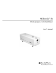
BTD 15.0 KW Generator
Water Injected
Exhaust Elbow
Fresh Water Fill Cap
Lube Oil Fill Cap
Control Panel ~
I.D. Plate
DC Charging
Alternator
Heat Exchanger
-----:.;:~
Lube Oil Filter
Lube Oil Drain Hose
Oil Pressure Switch
Zinc Anode
Lube Oil Dipstick
Oil Pressure Sender
15KW BTD
1
GENERAL
Introduction
This manual contains the equipment operating procedures as well as additional information needed to help
the operator keep the marine equipment in proper working order. Study and follow the instructions carefully. A planned maintenance program is included in this manual; adhering to the program will result in better
equipment performance and longer equipment life. Proper diagnosis of a problem is the most important step
to satisfactory repair; consequently, a troubleshooting table is included.
Understanding the Diesel Engine
The diesel engine closely resembles the gasoline engine, since the mechanism is essentially the same. The
cylinders are arranged above a closed crankcase; the crankshaft is of the same general type as that of a
gasoline engine; and the diesel engine has the same type of valves, camshaft, pistons, connecting rods and
lubricating system.
Therefore, to a great extent, a diesel engine requires the same preventive maintenance as a gasoline engine.
The most important factors are proper ventilation and proper maintenance of the fuel, lubricating and cooling systems. Replacement of fuel and lubricating filter elements at the time periods specified is a must, and
frequent checking for contamination (that is, water, sediment, etc.) in the fuel system is also essential. Another
important factor is the use of the same brand of high detergent diesel lubricating oil designed specifically for
diesel engines.
The diesel engine does differ from the gasoline engine, however, in its method of handling and firing of fuel.
The carburetor and ignition systems are done away with and in their place is a single component - the fuel
injection pump - which performs the function of both.
Ordering Parts
When contacting your Westerbeke dealer, parts distributor, or the factory about your Westerbeke unit, always provide the generator's model number, the engine's serial number and the generator's serial number
as they appear on the scarlet and gold nameplate located on the generator end. You must provide us with
this information so we may properly identify your unit.
Note that component locations in the manual are referenced from the front of the engine which is the pulley/drive belt end. (The flywheel/generator or transmission end is the rear end.) Left and right sides are determined by the engine; imagine straddling the engine and facing in the same direction as the front of the engine:
the left side is at your left, the right side at your right.
Westerbeke engines and generator sets are thoroughly checked and given a final run under various load
conditions before leaving the factory. This is done to ensure dependable operation, long service, and a satisfied owner.
Care at the factory during assembly, and thorough testing, have resulted in a Westerbeke diesel enginedriven generator capable of many thousands of hours of dependable service. However, the manufacturer
cannot control the treatment the unit receives in the field. That part is up to the owner/operator.
2
BTC 15.0 KW MARINE DIESEL GENERATOR SET
GENERAL SPECIFICATIONS
Engine Type
Diesel, 4-cycle, 4-cylinder, fresh water-cooled
Vertical, in-line overhead valve mechanism
(30 hp at 1800 rpms maximum)
Governor
Mechanical, centrifugal weight type
Combustion Chamber
Swirl chamber type
Bore & Stroke
3.307 x 3.701 inches (84 x 94 mm)
Piston Displacement
128 cubic inches (2.1 liters)
Firing Order
1-3-4-2
Direction of Rotation
Clockwise, when viewed from the front
Maximum Torque
79.6 Ib-ft (11 kg-m) at 1900 rpm
Compression Ratio
21 :1
Compression Pressure
355.5 psi (25 kg/cm2) at 150 - 200 rpm
Valve Timing
Intake Opens 30° BTDC
Intake Closes 50° ABDC
Exhaust Opens 74° BBDC
Exhaust Closes 30° ATDC
Valve Seat Angle
Intake 30°
Exhaust 30°
Valve Clearance
(engine cold)
Intake 0.0098 inches (0.25 mm)
Exhaust 0.0098 inches (0.25 mm)
Engine Speed
1800 rpm 60 Hertz
1500 rpm 50 Hertz
Dimensions
Height: 25.06 inches (637 mm)
Width: 18.13 inches (461 mm)
Length: 38.00 inches (945 mm)
Weight
683 Ibs (309.8 kgs)
Fuel Consumption
1.8 gph (6.81 Iph) at full rated
output (approximate)
Inclination
Continuous 15°
Temporary 20° (not to exceed 20 min.)
3
SYSTEM SPECIFICATIONS
FUEL SYSTEM
General
Open flow, totally self-bleeding
Fuel
No.2 Diesel oil (cetane rating of 45 or higher)
Fuel Injection Pump
CAY DPA Injection pump
Fuel Injection Timing
230 BTDC ± 0.50 (static timing)
Nozzle
Throttle type
Injectors
Bosch type
Lift Pump
12-Volt; lift capacity 6 ft (1.8 m)
Fuel Filter (on engine)
Spin-on replaceable cartridge
Air Cleaner
Metal screen type - cleanable
Air Flow (engine combustion)
67 cfm (1.89 cmm)
COOLING SYSTEM
General
Fresh water-cooled block
thermostatically-controlled
with heat exchanger
Operating Temperature
170 -1900 F (77 - 880 C)
Fresh Water Pump
Centrifugal type, metal impeller, belt-driven
Sea Water Pump
Positive displacement, rubber impeller, gear-driven
Sea Water Flow, at 1800 rpm
(measured before discharging
into exhaust elbow)
5.6 gallons per minute (21.2 Ipm)
System Capacity
10 qts (9.5 liters) approximate
LUBRICATION SYSTEM
General
Pressure type by Trochoid pump
gear-driven with external pressure relief valve
Oil Filter
Full flow, paper element, spin-on type #35828
Sump Capacity (includes filter)
7 qts (6.6 liters)
4
Operating Oil Pressure (engine hot)
35 - 45 psi (2.8 - 3.5 kg/cm2)
Oil Grade
API specification CF OR CG-4
ELECTRICAL SYSTEM
Starting Battery
12-Volt,(-) negative ground
Battery Capacity(C. C.A.)
300 - 400 cold cranking Amps
DC Charging Alternator
12-Volt DC, 50 Amp
Regulator
Internal regulator built into alternator
Starting Aid
Glow plug, sheathed type
Starter
12-Volt, 1.6KW, reduction type solenoid mounted
DC No-Load Current
90 Amp. (max.) at 11.5 Volts
DC Cranking Current
225 - 250 Amps (engine cold)
AC GENERATOR
General
Brushiess, four-pole, revolving field. Pre-lubricated, singlebearing design.
Reconnectable, single-phase transformer
regulation (optional solid-state voltage regulation).
Voltage 120 or 120/240 Volts - 60 Hertz
220 Volts - 50 Hertz
Voltage regulation: ± 5% no load to full load
Frequency rotation: ± 3 Hertz (5%) no load to full load
Rating - Single Phase
60 Hertz (1800 rpm)
15KW
50 Hertz (1500 rpm)
12KW
120 Volts
120/240 Volts
220 Volts
5
125 Amps
125/62.5 Amps
60 Amps
General
Brushless, six pole, revolving field. Sealed lubricated single bearing
design. 12 Lead reconnectable for low voltage WYE, high voltage
Delta. Solid State voltage regulator with protection circuitry.
Rating - Three Phase
15KW - 60 Hertz
12KW - 50 Hertz
Voltage - 3 Phase (60 Hertz)
Low voltage WYE 208 volts
High voltage WYE 480 volts
DELTA
240 volts
Voltage - 3 Phase (50 Hertz)
High voltage WYE
DELTA
Amperage - 3 Phase (60 Hertz)
Low voltage WYE 99 Amps
High voltage WYE 43 Amps
86 Amps
DELTA
Amperage - 3 Phase (50 Hertz)
High voltage WYE
DELTA
Generator Cooling
Air Requirements, (60 Hertz), at 1800 RPM
380 volts
220 volts
43 Amps
75 Amps
225 - 250 din (6.37 - 7.08 cmm)
NOTE: Increase air supply 15% for 50 Hertz operation (1500 rpm)
Engine Combustion Air
Requirements, (60 Hertz), at 1800 RPM
67
dm (1.89 cmm)
TUNE-UP SPECIFICATIONS
Injector Pressure
1707 psi (120 kglcm2 + 10kglcm2 - 0 kglcm2 )
Engine Timing
19° BTDC ± .5°
GENERATOR COMPARTMENT
Ambient Temperature
104° F(40°C) Maximum
NOTE: Forced ventilation should be provided as needed to maintain generator compartment ambient
temperature 1040 F.
6
INSTALLATION CHECKS
General
Because the crafts in which Westerbeke engines and generators are installed vary in design, installation procedures will vary according to your craft's specific design. It is not the intent of this section to advise
boatyards or installers on procedures already well-developed and well-understood. However, it is important
that the owner/operator realize there are details of the installation which require periodic checks to ensure
the best operating conditions for the equipment and safe operating conditions for the personnel on board.
Proper location and installation of the generator set in the vessel are of prime importance.
Factors in the installation that must be considered are ventilation, so as to cool the generator and to provide
air for engine combustion; exhaust system, to properly discharge raw cooling water, to quiet the exhaust
and to expel the exhaust gas; cooling water supply; fuel supply; and electrical connections.
Factors in the location that must be considered are proper support and access for servicing and repairs.
There are four 1/2-inch bolt holes in each generator mounting rail to properly secure the generator to its
mounting platform.
7
Location
The location should be such that it is dry, above low-lying vapor areas, and away from being splashed by
bilge water or water from above. It should be properly ventilated and accessible for minor servicing and
repairs. Access for major repairs should be given consideration as well. The location must be properly ventilated to provide the fresh cooling air for the generator end and for engine combustion. Hot generator discharge air must be removed from the generator area. The platform on which the generator and its mounting
rails are located should be strong enough to support the generator unit during all angles of vessel operation.
Exhaust System
The exhaust system provides an outlet line to vent engine exhaust gases out of and away from the vessel.
The system also discharges sea water which has passed through the engine's sea water circuit by mixing it
with hot exhaust gases. This mixing helps to cool the exhaust gases and exhaust elbows and pipe. The exhaust system and the sea water supply to the exhaust must be configured to prevent the siphoning of sea
water into the exhaust through the sea water cooling circuit and to prevent the entry of sea water into the exhaust through the circuit's thru-hull discharge port. If not prevented, sea water entering through the discharge port can fill the exhaust system's muffler and enter the engine's cylinders. This will prevent proper
starting and possibly cause damage to internal engine components.
SeaWater
Fump
Generator Above Water Line
The sea water supply hose to the exhaust system's water injection elbow should be routed Oooped) at least
12 inches above the vessel's water line. An anti-siphon break should be installed at the top of this loop when
the generator set is installed at or below the water line (see page 9). The top of the loop should be placed
high enough above the vessel's water line so as to remain above the water line when the vessel is underway,
no matter what the angle of heel or roll may be.
The sea water supply thru-hull seacock fittings must be of the flush-hull type. High-speed scoop type fittings
should not be used, as they tend to encourage siphoning.
8
Generator BeloN Water Line
The exhaust discharge from the water lift muffler should be routed well above the water line then downward
to the thru-hull discharge. This routing will prevent sea water from entering if the thru-hull discharge fitting
becomes submerged when the vessel heels or rolls while underway, or is subjected to following sea conditions. Refer to the figures for recommended exhaust system installations.
Exhaust Back-pressure
Exhaust back-pressure should be checked prior to
putting a generator into service. (Refer to the illustration.) Excessive back-pressure will affect the engine's ~
performance and the generator's power output.
~
To measure the engine's back-pressure, either a mercury manometer or a water column must be acquired.
A boatyard or marine mechanic should have a
manometer. A water column can be made by taking
a clear plastic tube and taping one end to a yardstick
and fitting the other end with a 1/4 inch NPT (National Pipe Tap) fitting. Fill the tube half-full with water. If
your generator set does not have a tapped hole in its
exhaust manifold, one must be drilled and tapped for
a 1/4-inch NPT fitting.
Measure baCk-pressure at the exhaust elbow when
the generator is under a full load. Back-pressure, as
measured by a manometer or water column, should
not be over the following specifications:
9
-Insulation
~.
. .. .
~/4
Exhaust
NPT
Elbow
48
3S
38
Exhaust
2S
28
\
2 inches of mercury
27 inches of water in a water column
15.6 ounces PSI
1.0 PSI
NOTE: Other pressure gauges may be available to test for exhaust back-pressure.
Oil Drain
An oil sump drain hose is installed on the engine with the discharge end secured by a bracket at the front of
the engine. Oil may be drained from this hose by removing the cap and the discharge end of the hose from
the support bracket and lowering the hose into a container. The hose cap fitting is 1/4 inch-NPT (National
Pipe Tap) and can be extended, or have a pump added, for easier removal of the old oil, if desired.
Cooling System
The generator's engine is fresh water cooled by an engine-mounted heat exchanger. Sea water is used as
the heat exchange's cooling medium. Sea water is pumped into the exchanger by a sea water pump and is
then injected into the exhaust discharge, carrying with it the heat removed from the engine's fresh water cooling system.
Sea water should be supplied to the sea water pump through a flush-type hull fitting using a wire-reinforced
hose between the thru-hull fitting and the sea water pump. This sea water should be directed through a
visual-type sea water strainer and then delivered to the pump. Hoses routed from the thru-hull fitting to the
strainer and to the sea water pump should be wire-reinforced to prevent the hose from collapsing during the
generator's operation (suction from the pump may collapse a non-reinforced hose). Sea water strainers
should be mounted at or below the water line to make sure the sea water line remains primed.
CAUTION
Do not use a scoop-type thru-hull fitting as a means of supplying sea water to the generator.
Water pressure against this type fitting, while the vessel is under way, can push sea water past
the sea water pump's impeller into the generator's exhaust system, filling it and the engine as
well. Flush-type, clear, thru-hull fittings are recommended and should be located on the hull
so as to be below the waterline during all angles of boat operation.
The use of common-type street elbows is not recommended for plumbing the sea water circuit. These generally have very restrictive inside diameters. Machined fittings are preferred.
Automatic Shutdown
High Exhaust Temperature Shutdown Switch (normally closed)
An exhaust temperature switch is located on the exhaust elbow. This switch will open and shut the fuel
solenoid OFF (which turns OFF the engine) should the switch's sensor indicate an excessive exhaust
temperature (an inadequate supply of sea water coolant causes high exhaust temperatures). This switch
opens at 260 - 2700 F (127 -1320 C). This switch resets at approximately 2250 F (10]0 C).
10
High Water Temperature Shutdown Switch (normally closed)
A high water temperature switch is located on the thermostat housing. This switch will open and shut the
fuel solenoids OFF (which turns OFF the engine) should the fresh water coolant's operating temperature
reach approximately 2050 F (960 C). This switch resets at 1950 F (10-r C).
Low Oil Pressure Shutdown Switch (normally open)
A low oil pressure shutdown switch is located off the engine's oil gallery. This switch's sensor monitors the
engine's oil pressure. Should the engine's oil pressure fall to 10 -15 psi, the switch will open shutting OFF
the fuel solenoid (which turns OFF the engine).
Although diesel engine exhaust gases are not as toxic as exhaust fumes from gasoline engines, carbon monoxide is present in diesel exhaust fumes. Carbon monoxide is a dangerous
gas that can cause unconsciousness and is potentially lethal. Some of the symptoms or signs
of carbon monoxide inhalation or poisoning are listed below.
o Dizziness
o Intense headache
o Weakness and sleepiness
o Vomiting
o Muscular twitching
o Throbbing in temples
If you experience any of the above symptoms, get out into fresh air immediately.
The best protection against carbon monoxide poisoning is a daily inspection of the complete exhaust system. Check for leaks around manifolds, gaskets, and welds. Make sure exhaust lines are not heating surrounding areas excessively. If excessive heat is present, correct the situation immediately. If you notice a
change in the sound or appearance of the exhaust system, shut down the unit immediately and have the
system inspected and repaired at once by a qualified mechanic.
Make sure there are no unnecessary objects suspended from any portion of the exhaust lines. Excessive
weight could cause deflection or distortion of the lines, resulting in damage or leaks. Inspect insulated portions of the exhaust system to ensure there is no deterioration of the insulation.
Intake System
Make sure the intake system (sea water cooling system) is in proper order. Check that the hull inlet, seacock
and strainer are unobstructed. Seacocks and strainers should be at least one size greater than the inlet
thread of the sea water pump. The strainer should be of the type that may be withdrawn for cleaning while
the vessel is at sea and should be mounted below the water line to ensure self-priming. Inspect the sea water
lines to ensure there are no collapsed sections, which would restrict water flow. Make sure there are no air
leaks at any of the connections.
11
Fuel System
The generator must have its own fuel supply; in other words, it must have its own pickup tube and primary
filter/water separator. DO NOT tee off another engine's fuel supply. The fuel system should be installed in
such a manner as to allow the engine-mounted fuel lift pump to maintain a positive inlet pressure to the injection pump under all operating conditions. The minimum size of the fuel supply line and fuel return line is
1/4 inch, inside diameter, and there should be a primary fuel filter installed between the fuel tank and the fuel
lift pump. A secondary fuel filter has been installed on the engine between the fuel lift pump and the injection pump; this filter has a replaceable filter element. Make sure that the fuel supply and return lines are
securely anchored to prevent chafing and that all fittings are sufficiently tightened to prevent leaking. Also
make sure your fuel system has a positive shut-off valve; know its location and how it operates.
Note: Ensure that the fuel pickup tubes in the fuel tank supplying the generator are clear of
any gauze or screen type strainers. These can easily clog and cause fuel starvation to the
generator's engine.
DO NOT use mechanical type check valves in lieu of a manual shut off valve.
Be sure there is a fire extinguisher installed near the unit and that it is properly maintained. Be familiar with
its use. An extinguisher with the NFPA rating of ABC is appropriate for all applications in this environment.
Electrical System
The electrical system should be checked to ensure that all wiring harnesses are properly tied down with
clamps or plastic ties and that all wiring harnesses are spaced at intervals close enough to prevent chafing
from vibration. Check to ensure that all engine harness connections are tight and that they are made to the
appropriate terminals.
Generator (AC Output)
Make sure that the AC output connections within the generator's distribution box are tight and in accordance
with the specific AC Load Connections diagram found later in this manual. (See the "BT GENERATOR" section of this manual, page 33.)
IIWARNINGII
Do not smoke or allow an open flame near batteries. Lead acid batteries emit hydrogen, a
highly-explosive gas.
Batteries
Make sure the positive ( + ) battery connection is connected to the battery connection of the starting solenoid.
The negative (-) battery connection should be connected to the system ground (engine block).
12
When servicing the battery or checking electrolyte level, wear rubber gloves, a rubber apron,
and eye protection. Battery acid may splash on the skin or into the eyes inadvertently when
removing electrolyte caps.
Check the battery's electrolyte level and specific gravity to ensure maximum engine starting efficiency. Make
sure the battery's terminals are clean and tight.
Ventilation
The ventilation requirements of the generator sets include the following: combustion air is required for the
engine cylinders; cooling air is required for the generator end; and ventilating air is required to clear the bilges below the generator, as well as the compartment in which the generator is located, of potentially toxic
and flammable diesel fumes. Refer to the "SYSTEM SPECIFICATIONS" section of this manual for the airflow
requirements of the generator set, page 5.
13
OPERATION
This section of the manual provides the operator with preparation, initial starting, break-in, starting (cold or
warm), and stopping procedures. Follow the procedures as presented, for the conditions indicated, and
your Westerbeke generator set will give you reliable performance and long service life.
Preparation for Starting
Take the steps described below in starting your engine for the first time or after a prolonged shutdown or
lay-up.
Fill your engine with oil up to or near the upper limit on the dipstick (the installation angle may have an effect
on the dipstick reading). Select a readily available lubricating oil with an API specification of CC or CD and
an SAE number suitable for the temperature in your operating area (see page 31). For the quantity of oil
needed in your generator's engine, refer to the "SYSTEM SPECIFICATION" section of this manual, page 4.
Each unit is supplied with a coolant recovery kit (part #24977) as standard equipment, to which the following applies:
a. Remove the pressure cap from the engine's exhaust manifold and slowly fill the engine's cooling system with a mixture of water and antifreeze suitable for your temperature zone. (See the "COOLING SYSTEM" section of this manual, page 26.) Replace the pressure cap on the manifold.
b. Make sure the plastic recovery tank is properly mounted near the unit (with the bracket provided) in a
location where it can be monitored and filled easily (see page 26). The recovery tank should be mounted
at manifold level or above.
c. Coolant should be added to the plastic recovery tank after the engine has been filled and started. After
its operating temperature has been reached, ensure that all air is expelled out of the engine's manifold
and the engine's cooling system. With the manifold filled and the pressure cap installed, fill the plastic
recovery tank half full. Monitor this recovery tank daily and add coolant as needed.
Fill the fuel tank with a good grade of No. 2 diesel fuel and prime the fuel system up to the engine. The
engine's fuel system is totally self-bleeding. Depress the PREHEAT switch for 15 to 30 seconds and monitor
the return fuel flow. When the returning fuel is free of air, the engine's fuel system is bled and the engine is
ready to start.
NOTE: When the PREHEAT switch is depressed, the glow plugs in the cylinder head are energized; use the PREHEAT switch intermittently to prevent overheating the glow plugs.
Activating the PREHEAT switch energizes the fuel run solenoid, drawing the throttle arm into
the preset run position. Ensure that the arm moves rapidly and smoothly.
Ensure that the Installation Checks have been made in accordance with those specified in the "INSTALLATION CHECKS" section of this manual (refer to page 7) and that there is no AC load on the generator.
14
Starting Procedure
0
o
PREHEAT
e
.~'.
START
@
.
"."'-
'-."
...'.
STOP
~
'~
...
"'.'
ELAPSED TIME
ImllUDI!I 0 II
Hours
GENERATOR
o
0
Standard Instrument Panel,
Switches and Gauges
NOTE: When the generator is stopped after use, the water temperature and oil pressure
gauges may stay at their running readings.
When the generator is next used, depressing the PREHEAT switch will cause the water
temperature and oil pressure gauge indicators to return to zero (deflect to the left of the gauge).
The DC voltmeter will register system Voltage. The electric on-engine fuel pump, glow plugs,
and fuel run solenoid are also energized.
Depress and hold the PREHEAT switch. Preheat according to the following chart:
Atmospheric Temperature
Preheating Time
+410 F (+50 C) or higher
+410 F (+50 C) to +230 F (_50 C)
+230 F (_50 C) or lower
Approx. 10 sec.
Approx. 20 sec.
Approx. 30 sec.
1 minute
Limit of continuous use
15
Proper glow plug function is indicated by a voltmeter drop when
the PREHEAT switch is depressed. This drop will be slight but
discernible. If no voltage drop is noted, it may indicate defective glow plugs or a faulty preheat circuit (check for loose connections).
While holding the PREHEAT switch depressed, depress the
START switch. The starter motor will run, thereby cranking the
engine. As soon as the engine runs, release the START switch,
but continue holding the PREHEAT switch depressed for 2 or 3
seconds. Release the PREHEAT switch when the oil pressure
reaches approximately 20 psi. This bypasses the Low Oil Pressure shutdown until the engine's oil pressure rises to its normal
running pressure. Now release the PREHEAT switch.
Should the engine not start when the START switch is
(Proper Glow Plug Indication)
depressed for 10 to 12 seconds, release both switches and wait 30 seconds; repeat the procedure above.
Never run the starter motor for more than 30 seconds at a time.
CAUTION
Prolonged cranking intervals without the engine starting can result in filling the exhaust
system attached to the engine with sea water coolant. This may happen because the
sea water pump is pumping sea water through the sea water cooling system during
cranking. This sea water can enter the engine'S cylinders via the exhaust manifold once
the exhaust system fills. Prevent this from happening by closing the sea water supply
thru-hull shutoff, drain the exhaust muffler, and correct the cause for the excessive engine cranking needed to obtain a start. Engine damage resulting from this type of sea
water entry is not a warrantable issue; the owner/operator should keep this in mind.
Once the engine starts, check instruments for proper oil pressure and battery charging Voltage. Never attempt to engage the starter while the engine is running. Apply a light load to the generator and allow the
engine's operating temperature to come up to 140 -150° F (60 - 66" C) before applying any heavy loads.
NOTE: Some unstable running may occur in a cold engine, but this condition should smooth
out as the operating temperature is reached (170 - 190° F) and when a load is applied to the
generator.
Stopping Procedure
Remove the AC electrical load from the generator and allow the generator to run for 3 to 5 minutes to stabilize its operating temperatures. Depress the STOP switch and hold it until the generator is completely
stopped. Now release the STOP switch.
Break-In Precautions
Because the generator set operates at 1800 rpm to produce 60 Hertz, or at 1500 rpm to produce 50 Hertz,
control of the generator's engine break-in is governed by the current drawn from the generator.
Do not attempt to break-in your generator set by running it without a load.
16
Upon starting the generator set, check for proper operation and then encourage a fast warm-up. For the first
10 hours of the generator's operation, run the generator set between 20 and 60 percent of full load.
After the first 10 hours of the generator's operation, the load may be increased to the rated full-load output.
Periodically vary the load.
Avoid overload at all times. An overload is signalled by a smoky exhaust, with reduced output voltage and
frequency. Monitor the current being drawn from the generator and keep it within the generator's rating.
Be aware of motor starting loads and the high current draw required for starting motors (see page 39 for an
"Amps for Starting" chart).
Starting Under Normal Conditions
Follow the procedure below for routine starting of the generator:
Check the engine's lubricating oil level prior to each day's use. Add oil as needed and maintain the oil level
at the high mark on the dipstick.
Check the coolant level in the plastic recovery tank.
NOTE: Excessive loss of coolant from the plastic recovery tank indicates a cooling system
leak. Check the entire cooling system; pressurize the system to locate the leak. In cases of
excessive coolant loss, the system must be refilled as outlined under the "Preparation for Starting" section of this manual, page 14.
Visually examine the unit; look for any abnormalities and correct them as needed.
Checkto ensure that there is sufficient fuel in the tank and examine the filter/separator bowls for contaminants.
Clean and drain the bowls as needed.
Start the generator following the procedure given under "Starting Procedure," page 15, and allow the engine's
operating temperature to reach 140 - 1500 F (60 - 660 C) before placing the generator under a heavy load.
Starting Under Cold Conditions
Under extremely cold temperatures, the following conditions can occur. Follow the instructions listed below
when operating your generator set in cold weather.
LUBRICATING OIL TURNS VISCOUS - Make certain that the lubricating oil used conforms with the ratings
for the prevailing atmospheric temperature. Refer to the "LUBRICATION SYSTEM" section of this manual,
page 31, for an atmospheric/oil viscosity specification table.
VOLTAGE ACROSS BATTERY TERMINALS DROPS - Make certain that the battery is fully charged to minimize voltage drop across the battery terminals.
THE TEMPERATURE OF THE INTAKE AIR IS LOW AND THE COMPRESSION TEMPERATURE DOES NOT
RISE ENOUGH -Allowthe glow plugs to operate sufficiently to aid in starting during the preheat period whenever the temperature of the intake air is low and when the compression temperature does not rise enough.
Refer to the preheat chart found in the "Starting Procedure" section of this manual, page 15.
17
FUEL SYSTEM
Diesel Fuel
Use No.2 diesel fuel with a cetane rating of 45. Never use kerosene or home heating oil.
In cold weather particularly, water vapor is produced by condensation when air is present in the fuel tank.
Keep fuel tank(s} full and completely free of dirt and water.
Fuel Filters
A primary fuel filter of the water
entrapment type must be installed
between the fuel tank and the engine. Such a filter, shown here, is
available from your local Westerbeke representative or your boatbuilder. This filter, adapted for the
boatbuilder's use, comes complete
with fittings for either hose or metal
tubing. Mount it in an accessible
place, inspect it often and drain off
water accumulation frequently.
If a water trap type filter is not installed between the fuel tank and the
engine-mounted fuel system, any
water in the fuel system will tend to
lay in the bottom of the electric lift
pump. Internal metal parts of the lift
pump will rust. Particles will pass on
to filters and eventually to the injection pump and injectors with damaging results and the possibility of
expensive repairs. Remember, water
damage to the engine's fuel system
is not covered under the Westerbeke warranty.
Although most boatbuilders supply a water trap/filter, some do not. Westerbeke offers a sedimenter/water
trap/filter as an optional extra at moderate cost. The filter is supplied with fittings for either hose or metal'
tubing fuel lines.
Generator models covered by this manual have two replaceable fuel filters in the engine-mounted fuel system. One is in the base of the electric fuel pump and the other in the filter assembly located just after the discharge side of the electric fuel pump.
The self-bleeding feature of the fuel system allows for easy servicing of the filters. Simply remove and replace
the filter elements. (Take care to catch any fuel when removing these filter elements.) Energize the PREHEAT
switch and allow the electric fuel pump to operate for 20 - 30 seconds to prime and bleed air from the system. (No fittings should be opened.) Then proceed to start the engine as you normally would. If the engine
fails to start, stop and wait a few moments, and then repeat the bleed procedure as indicated above.
18
Notes on Fuel System
The illustration that follows is an exploded view of a typical fuel system for 4-cylinder diesel-engine generators. The figure also illustrates the self-bleeding and priming system used by Westerbeke.
The Westerbeke self-bleeding fuel system is semiautomatic in operation. While it is unlikely that the operator
will be forced to service the system at sea, the possibility does exist. Therefore, it is recommended that banjo
washers, injector seat washers, electric lift pump filter and gasket, fuel filter and gasket be carried on board
at all times. Select the parts for your engine from the Parts List and purchase spares from your local Westerbeke Dealer or Distributor. For example, a fuel system hardware kit that contains sealing washers for on-engine fuel system components should be purchased.
If a leak should develop at a fuel banjo or sealing washer location and cannot be corrected by a simple
tightening of the fitting, replace the washers with one of those in the kit.
Replacing Filter Elements
After the first 50 hours of operation, replace the filter element located in the base of the electric fuel pump.
Remove the fuel pump's base using an open end wrench. Take care in catching the filter element and fuel
within the pump. Install a new element and sealing washer for the base. Ensure that the magnet is located
in the center of the base, and then reinstall the locking base onto the securing pins at the base of the pump.
This same service is required of the secondary fuel filter. This filter is a spin-on type. Simply unscrew the filter and replace it with a new cartridge. Take care in catching any fuel that may be spilt while removing the
cartridge.
MANUAL PRIMER
FUEL
IN-COMING
FILTER
ELEMENT
LI FT PUMP
SPIN-ON FUEL FILTER
After the first 50-hour change, the change period may be increased to 200 hours or once per season. Good
quality fuel filter/water separators installed along the fuel supply line between the fuel tank and the generator's engine, and which are serviced regularly, will increase the service life of the on-engine filters.
19
Fuel Injection Pump
The fuel injection pump is one of the most important components of the diesel engine and therefore calls for
the utmost caution in handling. Furthermore, the fuel injection pump has been thoroughly bench-tested and
should not be tampered with.
Running speed (Hertz) and timing adjustment are the only adjustments the servicing dealer can perform on
the injection pump. Other types of adjustments or repairs must be performed by a qualified injection service
shop.
ELECTRIC LIFT PUMP
INCOMING FUEL
INJECTOR PUMP
Typical Fuel System
To obtain long and satisfactory service from the injection pump, always use fuel which is free from impurities
and maintain a good filtration and water separation system between the fuel tank and generator engine. Service this system regularly; the injection pump it saves may be your own.
20
ELECTRICAL SYSTEM
Engine 12-Volt DC Control Circuit
The engine that drives the generator end has a 12-Volt DC electrical control circuit, as shown on the wiring
diagrams which follow on pages 22 and 23. Refer to these diagrams when troubleshooting or servicing
electrical components on the engine.
CAUTION
To avoid damaging the battery's charging circuit, never shut off the engine's battery switch
while the engine is running.
However, shut off the engine's battery switch to avoid electrical shorts when working on the
engine's electrical circuit.
Battery Specification
The minimum recommended capacity of the battery used in the engine's 12-Volt DC control circuit is 90 125 Ampere-Hours (minimum) for the generator set covered by this manual.
CAUTION
When quick-charging the battery with an external charger, be sure to disconnect the battery
cables from the battery. Leaving the charging circuit connected while quick-charging will
damage the alternator's diodes.
Alternator
CAUTION
When testing the alternator circuit (charging circuit), do not use a high-voltage tester such as
a megger; damaged diodes could result.
When operating the generator, do not disconnect the positive battery terminal from the B terminal on the alternator, nor disconnect the negative battery terminal from the ground.
When cleaning the engine/generator with a steam cleaner, be careful to keep steam away from
the alternator.
21
DC Control Circuit Wiring Diagram #36411
page 1 or 2
fJ
~
~'FTPUMP
~~===':'4:P:U::R~
__________________________'~,o~o~e~N____TB~:~9
.... '4 PUR
_~
"14 PuR
-
\
WATE~
)
0
Rg
AL TERNATOR
L)
~TE~'P sw.
-".
V.
WATER TEMP
,~R
FUEL
SOLENOID
'I~
(~-;"
~I'
GLOWPLUGS
(~"
OIL PRESSuRE SW,
(~"
·,0 CRN
01 L PRESSuRE
r-t=7-lf
SEl~~~-2
I
b(
1t'2REO
0
I
I GROUND'
I TO BLOCK
~
SENDER
~Ll RED
CIRCUIT
~
BREAKER~
STARTER
Q
CIRCUIT
BREAKERU
BATTERY-12V
~
~
EXHAUST TEMP
S\'JITCH
·IG sRN
EMERGENCY
STOP
SWITCH
'-)4 PUR/wHT
*12YEL/RED
~
--:;~
T 8-\
o
a:
r---
~~
"4REO
r---;~ l~G~~~~ :"H~~t ~~'*------'
30
L-----t---+------,/0~
""'-1--
'----+-+--+-i0 50
r--~t::=
I
COONECTING A
REMOTE PANEL
!
~€><I:::-I"--Jt--j---~
~ f-r'~'4~B~R~N____________+ ____+-~
"4PUR
·10 REO
·r'O:..:;W-"HT.:...+-__---'
Z
~~ ~ ~
z
~
o
I
I
~
w
'"
"
~L PRESS-:;;
~
8 )(
~
.- .-
.:~
0
~
0
,.-
I
?REHEAT
SWITCH
I
I
I
I
L
~
"'10 SLK
'--____-t'.,,'4'-'0"'"""'--,
I'-________
t-""'4-"'E,\ I I
;.
e30t:------+-----t---~
I'-f::::=:::l
~
START
SW ITCH
STep
SWITCH
-
I
ISTANDARD
[INSTRUMENT
I PANEL
I
I
_ _ _ _ _ -.1
'.
22
DC Control Circuit Wiring Diagram #36411
page 2 of2
PREHEAT
SOLENOI
t>
j.------~'~'~~::::===l
B
II
:
: ): C.8.
, t"0A
---.::~
C.fl,
fB2-3
10 "
rSJ~t'~
r"'""~"
; j
G
c-L
STOP SW.
PREHEAT
liFT PUMP
S"'.
P
,, ,
: STOP SW.
,
,
1
~
o p 5w.
E,T, 5w.
STARTING
W_T. SW.
FUEL SOU.NOIO
ANU STOI"PING INSTRUCTIO'JS
START:I.ALWAYS PUSH PRE-HEAT SWITCH FIPST. HOLD
2.WHILE
CONTINUING
FOt:: I:' TO E.O
SECCND<:::. A~ REQUIRED.
TO PUSH PRE. HEAT SWITCH, PUSH START SWitCH.
3,WHEN GENERATOR STARTS, RELEASE START SWITCH ONLY.
4. WHEN OIL PRESSURE REACH ES
APP~lOx
I M ATLY 20 P.S.I., RELEASE THE PRE-HEAT SW ITCH.
(THE PRE-HEi\T SWITCH OVERRIDES "HE LOW OIL PRESSUE SHUTDOWN CIRCUIT.)
STOP,
PUSH AND HOLD THE STOP SWITCH UNTIL THE GENERATOR STOPS COMPLETELY.
I. THIS PRODUCT IS PROTECTED BY A MANUAL RE':·ET CIRCUIT BREAKER LOCATED NEAR THE STARTER
AND AS CLOSE TO THE SOuRCE OF CURRE"I AS POSSIBLE. EXCESSivE
CURRENT DRAW
ANYWHERE
IN THE INSTRl fvlENT PANEL WIRING OR ENGINE WILL CAUSE THE BREAKER TO TRH~ I'J THIS EVENT
MOST GENERATORS WILL SHUT
SUPPLY.
DOw~
BECAUSE THE OPENED BREAKER DISCONNECTS THE FUEL
THEREFORE THE BUILDER/OWNER MUST BE SURE THAT THE 1;'I./SH"l.U~lENT PANEL WIRiNG
ANO E'JGINE ARE INSTALLED TO Pi\EVE\JT CONTACT BETWEE'\I ELECTRICAL DEVICES ANO SALT WATER.
2.AN ON-OFF SWITCH
i=ROM THE BATTEf..<'(
ENGINE
SHOUl\) BE INSTALLED IN THIS CIRCUIT TO DISCON'\IECT THE '3TARTER
:N AN E(.1ERGENCY AND WHEN LEAVING THE BOAT.TWELVE VOLT DIESEL
STARTERS TYPICALLY QRAW .::'00 TO 300 A:v1PS WHE:-.J
INDIVIDUAL
CONTI,..UOUS
A SWITCH
CRANKINr~
RATING
CRANKI:'IIG. THE
DURATION OF
CYCLES SHOULD NOT EXCEE.D 30 SECC'\\lDS. A SWITCH WITH
OF 175 M . .1PS I\T 12VDC WILL NORMALLY SERvE
r-'iUST \lEV(r-.( BE uSED TO"MAy-e"Tf1E
23
STAR:TE~
CIRCUIT.
A
THIS FUNCTION, BUT
The charging system consists of an alternator with an internal voltage regulator, an engine-mounted circuit
breaker, and a battery and connecting wires.
Because of the use of IC's (integrated circuits), the electronic voltage regulator is very compact and is built
into the rear bracket of the alternator.
Charging Voltage Test
If you suspect that the alternator is not producing enough voltage to charge the engine's battery, perform
the following voltage test.
AMPMETER
r-------......-'®""{ A
e
L
R
Interconnections for Charging Voltage Test
1. Using a voltmeter, connect the voltmeter's red wire clip to the B output terminal on the alternator. Refer to
the schematic shown above.
2. Connect the other voltmeter wire clip to a ground on the engine.
3. Start the generator and record the reading given by the voltmeter.
The voltage reading for a properly operating alternator should be between 13.5 to 14.5 volts. If your alternator is over or under charging, have it replaced or rebuilt by a reliable service shop. Before removing the
alternator for repair or replacement, ensure that 12-Volts excitation is present at the R terminal should the
above test show only battery voltage at the B output terminal.
24
COOLING SYSTEM
Description
Westerbeke marine diesel engines are designed and equipped for fresh water cooling. Heat produced in
the engine by combustion and friction is transferred to the fresh water which circulates throughout the engine. This circulating fresh water cools the engine block and its internal moving parts. The heat is transferred
externally from the fresh water to sea water by means of a heat exchanger, similar in function to an automotive radiator. Sea water flows through the tubes of the heat exchanger while fresh water flows around the
tubes; engine heat transferred to fresh water is conducted through the tube walls to the sea water which is
pumped into the exhaust system and discharged overboard. In basic terms, the engine is cooled by fresh
water, the fresh water is cooled by sea water, and the sea water carries the transferred heat over the side
through the exhaust system. The fresh water and sea water circuits are independent of each other. Using
only fresh water within the engine allows the cooling water passages to stay clean and free from harmful
deposits. The two independent circuits and their components are discussed in the following paragraphs.
Fresh Water Circuit
NOTE: Refer to paragraphs a and b in this section on the recommended antifreeze and water
mixture to be used as the fresh water coolant, and for information on filling the fresh water
system.
Fresh water is pumped through the engine by a belt-driven circulating pump, absorbing heat from the engine. The fresh water coolant circulates through the engine's block absorbing heat, then passes through
the thermostat into the exhaust manifold, then to the heat exchanger where it is cooled, and then is returned
to the engine block through the suction side of the fresh water circulating pump. When the engine is started
cold, external fresh water flow is prevented by the closed thermostat (although some fresh water flow is
bypassed around the thermostat to prevent the exhaust manifold from overheating). As the engine warms
up, the thermostat gradually opens, allowing the engine's fresh water coolant to flow unrestricted to the external portion of the cooling system.
a. Fresh Water Coolant (Antifreeze) Mixture.
It is recommended that a freshwater and antifreeze mixture be used year-round. Water, when it freezes, expands sufficiently to split the heat exchanger and crack the engine block. A water/antifreeze mixture of
proper concentration will prevent freezing (see page 26 for an antifreeze/water mixture chart).
Use soft water with few impurities, such as tap water (potable water) or rainwater. Never use hard or foul
water. Use of hard water or water containing impurities will lead to the collection of scale in the engine and
heat exchanger which will reduce the COOling system's efficiency.
Antifreeze of poor quality or without rust inhibitors will cause corrosion within the cooling system. Always
use antifreeze which is compatible with aluminum cooling system components and is made by a reliable
manufacturer. Never mix different brands of antifreeze.
Make sure that the cooling system of the engine is well cleaned before adding antifreeze.
Recommended antifreeze for year round use is ZEREX or PRESTONE with rust inhibitors.
In order to control the concentration of the mixture, mix the antifreeze and fresh water thoroughly before adding it to the cooling system.
25
ANTIFREEZE ADDITION DATA
Antifreeze
Concentration
%
13
23
Freezing
Temperature
eC)
°F
23
(-5)
14
(-10)
30
35
45
50
5
-4
-22
-40
(-15) (-20) (-30) (-40)
60
-58
(-58)
NOTE: It is advisable that the antifreeze concentration be selected on the basis of a temperature which is about 10° F (5° C) lower than the actual atmospheric temperature expected.
b. Filling the Fresh Water System
A coolant recovery tank kit is supplied with each Westerbeke diesel generator. The purpose of this recovery
tank is to allow for engine coolant expansion and contraction, during engine operation, without the loss of
coolant and without introducing air into the cooling system.
This coolant recovery tank should be installed at, or above, engine manifold level, in a location where it can
be easily monitored and where coolant can be easily added if needed (see the figure below). A stainless
steel mounting bracket is supplied with each kit along with a 30-inch length of clear plastic hose and clamps
to connect the hose between the engine's manifold fitting to the hose spud on the base of the recovery tank.
COOLANT RECOVERY TANK
PRESSURE CAP
COOLANT PASSAGE
Coolant Recovery Tank, Recommended Installation
Coolant from the engine, when heated during the engine's operation, will expand, lift the spring-loaded
manifold pressure cap, and enter the recovery tank via the hose connecting the recovery tank to the manifold.
When the engine is shut down and cools, a small check valve in the pressure cap is opened by the contraction of the engine's coolant, allowing some coolant in the recovery tank to be drawn back into the engine's
cooling system, free of air and without loss.
26
Fill the fresh water system as follows:
1. Remove the pressure cap from the manifold.
2. Pour a clean, fresh water coolant mixture into the manifold and allow enough time for the coolant to fill
the fresh water cooling system.
3. Replace the pressure cap on the manifold.
4. Remove the plastic cap from the coolant recovery tank and fill the tank with coolant halfway between the
ADD mark and the MAX mark. Replace the cap.
5. Start and run the engine long enough for the engine to warm up so that the thermostat will open, allowing the coolant to flow through the engine block and to the rest of the fresh water coolant system.
6. Add coolant to the recovery tank, as required, to top off the fresh water coolant system.
Thermostat
Generally, thermostats are of two types. One is simply a choking device which opens and closes as the
engine's temperature rises and falls. The second type has a bypass mechanism. Usually this is a disc on
the bottom of the thermostat which moves downward to close off an internal bypass passage within the
head. Since 1980, each type of thermostat has a hole punched through it. The hole is a bypass to prevent
the exhaust manifold from overheating during the engine's warm-up. Replacement thermostats must have
this design characteristic.
Sea Water Circuit
The sea water flow is created by a gear-driven, positive displacement, neoprene impeller pump. The pump
draws sea water directly from the ocean through the sea cock and sea water strainer and passes the water
to the heat exchanger's sea water inlet.
The sea water passes through the heat
exchanger's tubes, from which heat from
the fresh water system is absorbed, and
then is discharged from the cooling system overboard through the water-injected wet exhaust system.
A zinc anode, or pencil, is located in the
sea water cooling circuit within the heat
exchanger. The purpose of the zinc
anode is to sacrifice itself to electrolysis
action taking place in the sea water cooling circuit, thereby reducing the effects of
electrolysis on other components of the
system. The condition of the zinc anode
should be checked monthly and the
anode cleaned or replaced, as required.
Spare anodes should be carried on
board.
~
~
New
Anode
Rep~ace
C~ean
Rep~ace
Zinc Anode Conditions
27
or
Replace
Sea Water Pump
The sea water pump is a self-priming, gear-driven rotary pump with a non-ferrous housing and a neoprene
impeller. The impeller has flexible vanes which wipe against a curved cam plate within the impeller housing,
producing the pumping action. On no account should this pump be run dry. There should always be a spare
impeller and impeller cover gasket on board (an impeller kit).
Alternator (DC) and Water Pump Drive Belt Tension
Never attempt to adjust the drive belt's tension while the engine is in operation.
CAUTION
Excessive alternator and water pump drive belt tension can cause rapid wear of the belt and
reduce the service life of the fresh water pump and alternator shaft bearings. Excessive slack
or the presence of oil on the belt can cause belt slipping, resulting in high operating temperatures, as we" as insufficient alternator output.
The alternator and water pump drive belt is properly adjusted if the belt can be deflected no less than 3/8
inch and no more than 1/2 inch (10 mm, 12 mm) as the belt is depressed with the thumb at the midpoint between the two pulleys on the longest span of the belt. (See figure below.) A spare drive belt should be carried on board.
Alternator and Water Pump Belt Tension
28
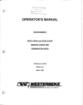
The following illustration shows the location of the zinc anode in the BTD 1S.0KW's heat exchanger unit.
ZINC AHODE
Heat Exchanger Unit of the BTD 1S.0KW Generator Set
29
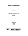
Illustrated below is a typical Westerbeke engine's cooling system. Both fresh water and sea water flow through
their independent cooling circuits.
TO HOT WATER TAN!(
OVEflHEAT ALARM
PUMP
II[OMII6 SEA VATER
Typical Cooling System
30
LUBRICATION SYSTEM
Engine Oil
FOR ENGINE LUBRICATION, USE LUBRICATING OIL DESIGNATED FOR DIESEL SERVICE.
THESE OILS ARE CLASSIFIED ACCORDING TO THE API SPECIFICATIONS INTO SERVICE
GRADES CC, CD CF AND CG-4. THE USE OF THE IDGHEST GRADE AVAILABLE IS
RECOMMENDED. THE OIL YOU SELECT SHOULD BE USED ON A REGULAR BASIS WHEN
POSSmLE.
Engine Oil Viscosity (SAE Number)
Use oil having a viscosity best suited to the atmospheric temperature. Use of an all-season oil SAE 10W-30
with minimum viscosity change under different temperatures is suggested.
Atmospheric Temperature
Viscosity
68° F (20° C) or higher
41° F (5° C) - 68° F (20° C)
41° F (5° C) - or lower
SAE 30 or 10W-30
SAE 20 or 10W-30
SAE 10W-30
NOTE: Do not use engine lube oil with an SAE number greater than 30 in generator engines.
Oil Pressure
The engine's oil pressure is indicated by the oil pressure gauge.
During normal operation, the engine's oil pressure will range between 35 and 55 psi (engine hot).
NOTE: A newly started, cold engine can have an oil pressure reading upwards of 60 to 80 psi.
A warmed engine can have an oil pressure reading as low as 35 psi. These readings may also
vary depending upon the load that is placed on the generator.
Your generator set is fitted with an oil pressure sensor. Should your engine's oil pressure drop below a safe
operating pressure, the sensor will shut the engine OFF to prevent any internal damage to your generator's
engine from occurring.
Engine Oil Change (to include filter)
1. Draining the Oil Sump
Discharge the old oil through the sump drain hose (attached at the front of the engine) while the engine is
still warm. Drain the old oil completely, replace the hose in its bracket and replace the end cap securely.
Always observe the old oil as it is removed. A yellow/gray emulsion indicates the presence of water in the
oil. Although this condition is rare, it does require prompt attention to prevent serious damage. Call a competent mechanic should water be present in the oil. Sea water present in the oil can be the result of a fault
in the exhaust system attached to the engine and/or a siphoning through the sea water cooling circuit into
the exhaust, filling it up into the engine (refer to the installation illustrations on pages 8 and 9).
31
2. Replacement of the Oil Filter
When removing the used oil filter, cover the filter
with a plastic bag containing a few cloth rags or
paper towels. This will allow both the filter element and spilled oil to be collected cleanly
without spilling oil on the engine or in the bilge.
(Oil or any other fluid on the engine reduces the
engine's cooling ability. Please keep your generator's engine clean.)
The replaceable cartridge-type oil filter requires
no cleaning inside.
When installing the oil filter element, apply a thin
coat of clean engine oil to the rubber gasket on
the oil filter, screw the filter onto the threaded oil
filter stub, and then tighten the filter firmly by
hand.
A
.~~
~
Oil Filter and Oil Drain System
NOTE: Generic filters are not recommended, as the material standards or diameters of important items on generic parts might be entirely different from genuine parts.
NOTE: Immediately after an oil filter change and oil fill, run the engine to ensure that the oil
pressure is normal and that there are no oil leaks around the new oil filter.
3. Filling the Oil Sump
Add fresh oil through the oil filler cap on the valve cover. After refilling the oil, run the engine for a few moments while checking the engine's oil pressure. Ensure there is no leakage around the new oil filter or from
the oil drain system, and then stop the engine. Then check the quantity of oil with the dipstick. Fill to, but
not over, the high mark on the dipstick, should the engine require additional oil.
32
BT GENERATOR
This generator is a four-pole, brushless, self-excited generator which requires only the driving force of the
engine to produce AC output. The copper and laminated iron in the exciter stator are responsible for the
self-exciting feature of this generator. The magnetic field produced causes an AC voltage to be induced into
the related exciter rotor windings during rotation. Diodes located in the exciter rotor rectify this voltage to
DC and supply it to the windings of the rotating field. This creates an electromagnetic field which rotates
through the windings of the main stator, inducing an AC voltage which is supplied to a load. A transformer
is connected in parallel to the AC output of the main stator. An AC voltage is produced in the auxiliary windings of the transformer and main stator and is, in tum, supplied to a full-wave bridge rectifier. The rectifier
produces a DC voltage to further excite the exciter stator windings, enabling the generator to produce a
rated AC output.
An optional solid-state voltage regulator is available to work in tandem with the transformer regulator to
produce a more stable AC output (see the top of page 34).
No-Load Voltage Adjustment
Voltage adjustment is made with the compound transformer governing generator regulation.
1. The selector switch must be in the CaMP position.
2. Operate the generator and apply a moderate load momentarily; then remove the load. Note the voltage
output from the generator's 120-Volt leg(s) (110 Volts at 50 Hertz). The no-load voltage should be between 121 - 123 Volts at 61.5 - 62 Hertz (111 - 113 Volts at 51.5 - 52 Hertz).
NOTE: The no-load voltage should be adjusted to the voltage produced by the generator
when: the generator is started, a momentary load is applied to excite the transformer, and
then removed. The voltage produced by the generator after this momentary load is removed
is the no-load voltage.
3. To raise or lower the voltage, non-conductive shims of varying thickness are inserted or removed from
under the laminated steel bar that is situated on top of the compound transformer. The material used for
shimming should not soften at temperatures in the 1760 F (800 C) range. A small reduction in no-load voltage (1 to 3 Volts) sometimes can be accomplished by gently tapping the top of the laminated steel bar to
reduce the air gap between the existing shims and the transformer core.
See the next page for an illustration of the generator's AC distribution box.
33
YellowfWhite
Optional AVR
BlackIWhite
Generator AC Distribution Box
BTD 15.0KW Generator Set
CAUTION
Under no circumstances attempt to increase the no-load voltage by increasing the gap between the laminated steel bar and the transformer core without the use of shims. Magnetic
forces created within the transformer during the generator's operation may close the air gap
and reduce the no-load voltage output.
4. To remove the laminated steel bar, remove the two upper securing bolts from the compound transformer
and lift the bar from the transformer. The addition of shim thickness will raise the no-load voltage and,
conversely, the removal of shim thickness will lower the no-load voltage.
Varying shim thickness by.001 inch (0.025 mm) will change the no-load voltage by 4 to 6 Volts.
34
r--------,
--------1
C
r-
1[=
r-
+
-
-
I
I
I
I
1- _ _ _ _ _ _ _ _ _ _ _ _ _
I
2
!
- - ---
c
~
Green
Red
Black
YIYeliow
F
Red
/f<'
I ,
/
:
0
I
I
e
m
I
I
I
..J
--+-!- :
•
I
2
3==7'r==
~~~~I--
-rI
1010101171101
-
i
'l+~
-7
~
-8
A
L
7 '---_ _---.J
I
I
I
_J
Red
*-
/- L - -
Green
Green
Black
Black
I \ Yellow
I
E L
3
2
Yellow/Red
Black
AC
T B
_6
I
I
I
I
I
I
I
-s
I
I
I
I 1
I
3
Green
•
I
I
I
I
-.J
G
+'----
I
I
'---11-'-!~i
I 4 I
I
-{>I-
I
Black
+
Yellow
-
~t
'---:l
Blue
PLUG
Blue
IAVR.,
CI>
CI>
'" 10'"
10
60 cyc.
SOcyc.
BTD 15.0KW Generator's Internal Wiring Diagram
A. EXCITER STATOR WINDINGS
1. Exciter Stator Windings
2. Exciter Stator Windings
D.COMPOUNDTRANSFORMER
1. Compound Transformer Windings
2. Compound Transformer Windings
3. Compound Transformer Auxiliary
Windings
B. EXCITER ROTOR
1. Auxiliary Windings (a - b - c)
2. Diodes (6)
3. Rotating Field Windings
4. Pozi Resistor
F. SELECTOR SWITCH
1. Compound
2. Electronic and Compound
C. MAIN STATOR
1. Main Stator Windings
2; Main Stator Windings
3. Main Stator Auxiliary Windings
G. BRIDGE RECTIFIER
(Optional A.V.R - Automatic Voltage Regulator)
8
~ K
Optional Voltage Regulator
An optional solid-state voltage regulator (board #34410) is available for use with the BT series generators.
When installed, and the regulation switch is moved to the ELEC position, the regulator works together with
the standard compound transformer regulator to regulate the generator's voltage output. In the ELEC mode,
the regulator provides excitation to the group 1 exciter windings, and the transformer provides excitation to
the group 2 exciter windings.
Installation
1. The regulator is mounted using existing tapped holes in the generator's case. Use two (2) M4 x 0.7-mm
screws, each 15 mm long, with lock washers to mount the regulator board.
2. Connect the 6-prong generator plug to the receptacle on the regulator board.
NOTE: The plug is keyed to engage the regulator receptacle in one direction. Check this and
insert it correctly.
3. Before moving the selector switch to ELEC, ensure that the no-load voltage produced by the generator is
properly adjusted, with the selector in COMP position, by following the procedures for "No-Load Voltage
Adjustment," page 33.
4. With the generator's no-load voltage properly adjusted, move the selector switch into the ELEC position.
Adjust the regulator board potentiometer to set no-load voltage at 120 Volts, 61.5 - 62 Hertz (110 Volts,
51.5 - 52 Hertz). The generator's voltage output should be within ±5 percent from no-load to full-load.
Generator Frequency
Frequency is a direct result of engine/generator speed:
1800 RPM - 60 Hertz
1500 RPM - 50 Hertz
To change the generator's frequency, refer to the "MAINTENANCE AND ADJUSTMENTS" section of this
manual, page 48.
Load Connections
The generator's data plate gives the voltage, current and frequency rating of the generator. An AC wiring
decal is affixed to the inside of the louvered cover on the generator end. A diagram of the various AC voltage connections is provided on the decal. The information on the decal is similar to the figure shown on the
following page.
The generator is a single-phase, reconnectable 120 Volts AC two-wire or 120/240 Volts AC three-wire, at 60
Hertz; or 110 Volts AC two-wire, 110/220 Volts AC three-wire, or 220 Volts AC two-wire, at 50 Hertz. Refer to
the "SYSTEM SPECIFICATIONS" section of this manual for ratings, page 5.
36
NOTE: We recommend that the installer provide AC ampmeters (optional) so that the operator
can observe the load being taken off each leg of the generator.
A circuit breaker should be installed between the generator and the AC load. This circuit breaker should be
rated for the generator's AC output and be able to react quickly to overloads, subject to motor starting considerations.
120V 60Hz
1281240V 60Hz
II
Os
7 (5
03
8
110V 50Hz
1101220V 50Hz
sO
220V 50Hz
sO
II
02
sO
Os
70)
II
AC Voltage Connections (6 Stud Terminal Block)
15.0KW Generator Set
NOTE: The frame ground wire must be moved when changing from 110 Volts, 50 Hertz to
220 Volts, 50 Hertz.
For making connections to the AC terminal block, use 1/4 inch terminal ends that will accept multi-strand
wire sized for the number of conductors in the bundle, the rating of the conductor's insulation, and amperage
that will be drawn through the conductor(s). (Refer to the generator's scarlet and gold data plate for generator amperage ratings.)
37
Shore Power Connections
If the installer connects shore power to the vessel's AC circuit, this must be done by means of the SHORE
POWER/OFF/SHIPS GEN, center position-off transfer switch as shown below. Use of this switch prevents
simultaneous connection of shore power to generator output.
CAUTION
Damage to the generator can result if utility shore power and generator output are connected
at the same time. This type of generator damage is not covered under the warranty; it is the
installer's responsibility to ensure that all AC connections are correct.
Generator
HOTE:
~
t T<---_----,
I
I
/""--.. .
~\.... ---,
r-----\Q)
I
I
I
....../
L------r-<D
,
iz
I
I
I
I
I
I
I
I
I
I
I
SHIP-TO-SHORE SWITCH
[3 POLE]
PH 32888
[48 AMPS/POLE]
I
L_L2
PH
32an
[BB AMPS/POLE]
PH 32818
1125 AMPS/POLE]
Ship'S
LOAD
NOTE: DIAGRAM SHOWS CONNECTIONS FOR A TWOWIRE. 12B-VOLT SYSTEM FROM THE GENERATOR,
WITH THREE-WIRE, 12B-UOLT
BOIlT SYSTEM .
Generator
IN
PH 32133
[288 AMPS/POLE]
Gl~
t
/
....
. .!,
~
~'!
ii
Z
"
.......
\
..J
!!\t
'-
~r
4....
~
:"...
Ship·l0-Sh0re Sw~ch (3 Pole)
l ....
.~
PH
(48
L2
- ....,
~
32BBB
AMPS/POLE)
PH
32890
(Blil AMPS/POLE)
.....
J[i
~\_-t--,N~eutr~al'--.N
-_....
J
(WHT)
/
.::;:Grou~nd::---4_ _ _--Illt.
(GRN)
PH
Ship'Slcad
Note
NO 24(].Vol1
equipment
PM 32133
(28B
Shore Power Switch Connection Diagrams
38
328111
(.125 AMPS/POLE)
AMPS/POLE)
GENERAL INFORMATION AND CARE OF THE GENERATOR
Use of Electric Motors
The power required to start an electric motor is considerably more than is required to keep it running after
it is started. Some motors require much more current to start than others. Split-phase (AC) motors require
more current to start, under similar circumstances, than other types. They are commonly used on easystarting loads, such as washing machines, or where loads are applied after the motor is started, such as
small power tools. Because they require 5 to 7 times as much current to start as to run, their use should be
avoided, whenever possible, if the electric motor is to be driven by a small generator. Capacitor and repulsion-induction motors require from 2 to 4 times as much current to start as to run. The current required to
start any motor varies with the load connected to it. An electric motor connected to an air compressor, for
example, will require more current than a motor to which no load is connected.
In general, the current required to start 115-Volt motors connected to medium starting loads will be approXimately as follows:
MOTOR
SIZE
(HP)
AMPS FOR
RUNNING
(Amperes)
1/6
1/4
1/3
1/2
3/4
1
3.2
4.6
5.2
7.2
10.2
13
AMPS FOR
STARTING
(Amperes)
6.4 to 22.4*
9.2 to 32.2*
10.4 to 72.8*
14.4 to 29.2
20.4 to 40.8
26 t052
* Note that in the above table the maximum "Amps for Starting" is more for some small motors
than for larger ones. The reason for this is that the hardest starting types (split-phase) are not
made in larger sizes.
Because the heavy surge of current needed for starting motors is required for only an instant, the generator
will not be damaged if it can bring the motor up to speed in a few seconds. If difficulty is experienced in
starting motors, turn off all other electrical loads and, if possible, reduce the load on the electric motor.
Required Operating Speed
Although individual units may vary slightly, the normal voltage and frequency of typical 60-(50-) Hertz enginedriven generators described in this manual are approximately as follows: run first with no load applied, then
at half the generator's capacity, and finally loaded to its full capacity as indicated on the generator's data
plate.
See the rpm/Hertz/frequency chart on the next page.
39
4-Pole
Speed
(rpm)
None
Half
Load
Applied
Full
Frequency
(Hertz)
Generator
120V(110)
Plants
Voltage
240V (220)
Plants
1830
(1530)
62
(52)
122
(112)
244
(224)
1800
(1500)
60
(50)
120
(110)
240
(220)
1755
(1455)
59
(49)
110
(100)
220
(200)
The output voltage should be checked periodically to ensure proper operation of the generating plant and
the appliances it supplies.
If an AC voltmeter or ampmeter is not installed to monitor voltage and load, check it with a portable meter
and amp-probe.
Preventive Maintenance (Generator)
Maintenance on the generator is minimal.
1. Keep the generator clean, dry and well-ventilated.
2. Ensure that all connections are clean and tight and that cables carrying AC voltage are properly supported
and protected against chafing.
3. The rear armature bearing is lubricated and sealed; therefore, no maintenance is required. If the bearing
becomes rough or noisy, replace it.
Generator Troubleshooting
A complete and illustrated text on troubleshooting the BTD series of generators is furnished in the Technical
Manual which is available through your local dealer.
40
ENGINE CONTROL PANEL
General
Standard Instrument Panel
This manually-controlled series of
Westerbeke marine diesel generators is equipped with toggle
switches on the engine's control
panel and, optionally, at remote
panels. The following instructions
and methods of correcting minor
problems apply only to such toggle switch controls.
o
PREHEAT
o
~
~
START
4
~
All three switches are momentary
contact type and serve the following functions:
STOP
A
~
1. PREHEAT: The PREHEAT tog-
gle switch is a double-pole,
QiNERATOR
single-throw switch. The switch
serves two purposes: preheating the engine for easy starting
and defeating or bypassing the
engine's protective oil pressure
sensor. The defeat function
turns on the fuel solenoid, instrument power, alternator excitation and provides power to the START switch.
o
o
2. SIABI: The STARTtoggle switch is a double-pole, single-throw switch. The switch, when activated, energizes the starter solenoid for starting the engine. This switch will not operate electrically unless the
PREHEAT switch is depressed and held at the same time.
3..sIQE.: The STOP toggle switch is a single-pole, single-throw, normally-closed switch. This switch
provides power to the fuel solenoid, instrument cluster and alternator excitation, after the oil pressure
switch has closed upon starting. Opening of this switch opens the power circuit to the fuel solenoid, thus
stopping the flow of fuel to the engine and stopping the engine.
4. In addition to the three switches above, the Standard Instrument Panel used with Westerbeke diesel generator sets includes two gauges, which indicate water temperature in degrees Fahrenheit (WATER 0 F)
and oil pressure in pounds per square inch (OIL PSI), and two meters, which indicate DC control circuit
voltage (VOLTS) and generator running time (ELAPSED TIME) in HOURS and 1/10 hours. The Water
Temperature and Oil Pressure gauges, and the DC Voltmeter are illuminated; the ELAPSED TIME meter
is not.
41
Engine Operation
To start the engine, perform the following steps:
I. Preheat - Depress the PREHEAT switch. The voltmeter, panel lights, gauges and meters and fuel solenoid
will be activated. The PREHEAT switch should be depressed in accordance with the chart in the "OPERATION" section under "Starting Procedure," page 15.
2. Start - While still depressing the PREHEAT switch, depress the START switch. This will engage the start
solenoid. Panel power and the fuel solenoid will be activated. Upon engine firing, release the START
switch. Do not release the PREHEAT switch until the oil pressure reaches 15 psi. Then as long as the high
water temperature, low oil pressure and exhaust temperature protective circuits do not activate, the set
will remain energized and continue to run.
3. Stop - Depress the STOP switch to stop the engine. This opens the power feed to the fuel solenoid, stopping the fuel flow to the engine. The STOP switch must be held depressed until the generator stops rotating.
Remote Operation
For remote operation of the generator system, the same three switches are used. The PREHEAT and
START switches are connected in parallel with the local panel's switches and serve the same functions as
in the local panel. The STOP switch is in series with the local panel's STOP switch, and serves the same
functions as in the local panel. The generator may be stopped from local or remote positions.
REMOTE CONTROL PANEL (REAR VIEW)
,-------------------------------------------------'
,
,
"
: 55 A SURGE
, 22 A START
, 3 A RUM
,
i
"
:
:
!..---
I
I
:
!,
!
:
0
'
STOP
SWITCH
"
i,
i:
®
,
:---,..-------------r-------------------RED/WHITE
TO T82-1
"
r---
110 BLACK
:
I
!
I
___________
I
I
l_
~-~L----------.P.!'!!p.g-
TO T82-2
,
I
PREHEAT
SW ITCH
i,
!
I
I:!
i
!
i,
TO lBl-6ND
I
I
,
m::::[J-!!ll!-
TOT81-1
i,
I
I,
I!
,
RED
r--------------------------------------------------~-------------------~
,:
,
55 A SURGE
22 A START
___________ ~~-A-~U!-----------R.!~-114 RED
TO T81-2
','
114 RED
'
i
=~~_=_~=~~_=_~=~~_=_~=~~_=_~=~~~_~=~~~_~ ~~_=_~~=~~~J ~5_ ~ oS!~~T
--.
P.N. 24943
42
, 48 A SURGE
- - - - - - - _!H11E_ TO T81- 4
ENGINE TROUBLESHOOTING
Introduction
The tables which follow indicate troubleshooting procedures based upon certain problem indicators, the
probable causes of the problems, and the recommendations to overcome these problems.
Note that the engine's control system (electrical system) is protected by a 20-Ampere manual reset circuit
breaker located on the rear lifting eye bracket. The preheat solenoid is close by, as is the emergency STOP
switch, which may be mounted on the same bracket or on the back of the standard instrument panel, depending upon the model.
43
ENGINE TROUBLESHOOTING
Problem
Probable Cause
Verification/Remedy
PREHEAT switch is depressed: no panel indications, fuel solenoid, electric fuel
pump and preheat solenoid not energized.
Battery switch
not on.
Check switch and/or
battery connections.
5TART switch is depressed: no starter
engagement.
START switch is depressed: panel indications OK; start
solenoid OK; fuel
solenoid not functioning.
20-Amp circuit
breaker tripped.
Reset breaker; if
breaker trips again,
check preheat solenoid circuit and run
circuit for shorts
to ground.
Connection to
solenoid faulty.
Check connection.
Faulty START switch.
Check switch with
ohmmeter.
Faulty solenoid.
Check that 12 Volts is
present at solenoid
connection.
Loose battery
connection.
Check battery
connection.
Low batteries.
Check battery charge
state.
Poor connections to
fuel solenoid.
Check connections.
Defective fuel solenoid.
1. Check mechanical
positioning of fuel
solenoid for plunger
bottoming.
2. Manually check
movement of fuel
solenoid plunger
and throttle arm.
3. Check for voltage
drop at solenoid
during PREHEAT.
Check wire size
from remote panels.
44
problem
probable Cause
Verification/Remedy
No ignition: cranks,
but does not start;
fuel solenoid energized.
Faulty fueling system.
1. Check for fuel
to generator engine.
2. Check for air in
fuel system. Allow
system to self-bleed.
3. Fuel lift pump
faulty.
4. Filters clogged.
(Replace filters
and allow system to
self-bleed by depressing only the
PREHEAT switch.)
Failure to stop.
Fuel solenoid
return spring.
Stop engine by manually moving the
throttle lever to shut
off. That failing,
shut off fuel and air.
Check fuel solenoid
linkage and repair for
free movement.
STOP switch failure.
Stop engine by depressing emergency STOP
switch on engine or
manually moving throttle to shut off. Test
switch with ohmmeter.
Fuel injection pump
failure.
Depress emergency
STOP switch on engine.
Stop engine by opening
the high pressure injector lines at the
injectors and stop air
intake.
Low oil pressure or
overheated.
Check oil level; check
fresh and sea water
cooling.
Low oil pressure
switch opens.
Check for satisfactory
operation with switch
bypassed. Check with
ohmmeter.
Engine stops.
45
probable Cause
Verification/Remedy
High water temperature switch opens at
too Iowa temperature.
Check for satisfactory
operation with switch
bypassed. Check with
an ohmmeter.
20-Amp circuit breaker
tripping.
Same as above.
High exhaust temperature switch opens at
too Iowa temperature.
Same as above.
Emergency STOP switch
or STOP switch in
panel defective,
opening fuel run solenoid circuit.
Check operation of
switch with an
ohmmeter.
Switches and/or
wiring.
Inspect all wiring
for loose connections
and short circuits.
Inspect switches for
proper operation.
Battery not charging.
Alternator drive.
Check drive belt tension. Be sure alternator turns freely.
Check for loose connections. Check output
with voltmeter. Ensure
12 Volts present at
regulator terminal.
Battery runs down.
Oil pressure switch.
Observe if gauges and
panel lights are activated when engine
is not running. Test
the oil pressure
switch.
problem
Engine Stops (continued).
46
Problem
Probable Cause
VerificationlRemedy
High resistance leak
to ground.
Check wiring. Insert
sensitive (0-.25 Amp)
meter in battery lines.
(Do not start engine.)
Remove connections and
replace after short is
located.
Low resistance leak.
Check all wires for
temperature rise to
locate fault.
Alternator.
Disconnect alternator
at output, after a
good battery charging.
If leakage stops, remove alternator and
bench test. Repair or
replace.
Battery runs down (continued).
47
MAINTENANCE AND ADJUSTMENTS
Introduction
This section contains a scheduled preventive maintenance program and several adjustment procedures the
owner/operator can perform without the benefit of sophisticated and expensive tools and instruments.
Preventive Maintenance (Engine)
Perform the preventive maintenance in accordance with the schedules listed in the following paragraphs.
Adherence to these schedules will ensure the equipment is maintained in the best possible condition and
that it will perform to expectations. Those items marked by an asterisk (*) are recommended to be performed
by an authorized dealer or distributor.
Daily (before each use)
1. Check the oil sump's level. Maintain the oil level at or near upper level mark on dipstick.
2. Check coolant level in plastic recovery tank. Maintain at or above the level marked ADD.
3. Visually inspect the unit; check for loose belts, chafed or broken wires, loose brackets and fittings,
damaged hoses, loose clamps, and other equipment not properly secured.
4. Check the fuel supply. Fill with a good grade of No.2 diesel fuel, if required.
5. Check the primary filter/water separator. Drain and service as required. (A primary filter/water separator
is optional, but strongly recommended.)
6. Check the engine's gauges for proper oil pressure, operating temperature, and starting battery charging voltage once the engine is operating.
7. Check the generator's output meters (when installed) for proper AC voltage and output frequency.
Monthly
Check the condition of the zinc anode in the heat exchanger sea water circuit. Clean or replace the anode,
as required. Keep the area inside the heat exchanger clean of zinc anode debris.
Servicing After Initial 50 Hours of Operation
1. Change the engine's lube oil and oil filter.
2. Replace the fuel filter elements in the electric fuel lift pump and in the engine-mounted filter assembly.
*3. Torque the cylinder head hold-down bolts.
*4. Adjust valve clearances.
48
5. Adjust the alternator and water pump drive belt tension, if required.
6. Adjust the engine's no-load speed, if required (Hertz). Please note that this adjustment is not a warrantable
adjustment during or after the unit's break-in.
Servicing After Every 100 Hours of Operation
1. Change the engine's lube oil and oil filter.
2. Adjust the alternator and water pump drive belt tension, if required.
3. Check siphon break operation (when installed).
Servicing After Every 250 Hours of Operation
Replace the fuel filter elements in the electric fuel lift pump and in the engine-mounted filter assembly.
Servicing After Every 500 Hours of Operation
*1. Torque the cylinder head hold down bolts.
*2. Adjust the valve clearances.
3. Drain, flush, and refill the fresh water cooling system.
*4. Check the condition of the starter motor drive pinion; lubricate pinion.
5. Check for proper operation of preheat circuit and glow plugs.
*6. Check the generator for proper operation. Also check the generator's AC output connections for security make
sure that these connections are not chafing.
7. Check the outside of the engine. Make sure that any oil on the engine's surface is cleaned. Any dirt or oil on the
engine inhibits the engine's ability to remain cooL Please keep th engine clean.
8. Check the condition of the DC battery charging alternator making sure that all the connections are clean and
secure and that the alternator's voltage output is correct.
9. Check the condition of the sea water pump making sure that the pump's impeller is serviceable. Check the
internal wear of the pump, and replace worn components as needed.
10. Check water injected exhaust elbow for carbon andlor corrosion build-up on inside passages. Clean/replace as
needed.
11. Inspect sea water pump drive. Remove the pump and check drive tank and pump shaft. Replace as needed.
49
Servicing After Every 800 Hours of Operation
*1. Remove and check fuel injectors
Injector spray pressure:
1706 psi + 142 psi
(120 kglcm2 + 10 kglcm2)
Eliminate undesirable injection conditions including after dripping.
~~~
.. ~~+;
. . .~lIi'lliiiN"""_.--~o1i\
*2. Check compression pressure. Remove
each glow plug and check each
cylinder's compression pressure. The
engine's cranking speed is at 250 rpm.
GOOD
BTD15.0KW
Minimum
Standard
440 psi
(31 kglcm 2)
355.5 psi
(25 kg/cm2)
Maximum difference between cylinders: 35.5 psi (2.5 kg/cm2)
*3. Check the battery-charging alternator for proper operation.
*4. Check the tightness of bolts, nuts, and clamps.
Servicing After Every 1000 Hours of Operation
1. Remove, clean, and pressure test the primary heat exchanger. (A local automotive radiator shop should
be able to clean and test the heat exchanger.)
NOTE: Operating in silty and/or tropical waters may require that a heat exchanger cleaning
be performed more often than every 1000 hours.
*2. Check the injection pump's timing.
Preventive Maintenance (Generator)
Maintenance on the generator end is minimal:
1. Keep the generator clean, dry, and well-ventilated.
2. Ensure that all connections are clean and tight, and that cables carrying AC voltage are properly supported and protected against chafing.
*3. The rear armature bearing is lubricated and sealed; no maintenance is required. However, if the bearing becomes noisy or rough-sounding, have it replaced.
50
Adjustments (Engine)
Valve Clearance Adjustment
Pull the air breather hose off of the rocker cover; loosen and remove the rocker cover bolts.
- Exhaust Side -
o
oo
14
o
o
8
10 11
12
o
0
4
o
0
@
1
2
0
5
o
@J
15
13
o
q
3
- Intake Side Cylinder Head Bolt Tightening Sequence
1. Tighten the cylinder head bolts in the sequence shown above. The engine should be cold. Loosen each
bolt 1/8 to 1/4 turn when tightening in the sequence shown. Note that bolt # 4 and 5 are located under
the intake manifold where it is attached to the head.
Head Bolt Tightening Torque
Exhaust Side - 12.0 kg-m (86 Ib-ft)
Intake Side
- 10.5 kg-m (76Ib-ft)
2. Tighten each rocker shaft bracket bolt to 11 Ib-ft (1.5 kg-m).
3. Adjust the valves' clearances with the engine cold after the cylinder head bolts have been re-torqued as
described in step #1.
A. Slowly rotate the crankshaft in its normal direction of rotation to bring the piston of the number 1 cylinder
(as viewed from the front of the engine) to Top dead Center (TOC) of its compression stroke. Observe
that when this is done, the valves of the number 4 cylinder are in a position of overlap; that is, both valves are closed.
51
B. In this position, adjust the valve's clearance in the conventional manner of the intake and exhaust valve
of the number 1 cylinder, the intake valve of the number 2 cylinder, and the exhaust valve of the number 3 cylinder.
C. Rotate the crankshaft in the normal direction of rotation one full turn (360°) and stop.
D. In this position, adjust the valve clearances of the intake and exhaust valve of the number 4 cylinder,
the exhaust valve of the number 2 cylinder, and the intake valve of the number 3 cylinder.
Exhaust valves
Inlet valves
Valve Clearance (engine cold)
.010 inches (0.25 mm)
52
Injection Pump Timing BTD 15.0KW
Incorrect fuel injection timing will result in hard engine starting and poor engine performance. Adjust the injection timing as follows:
1. Locate the timing pointer on the front gear
cover. This pointer is located at about the
10:00 o'clock position when viewing the
front crankshaft pulley.
Timing pointer
Front pulley
2. The front crankshaft pulley has timing marks
embossed on its circumference from 0° TDC
(Top Dead Center) to 40° BTDC (Before Top
Dead Center) in five-degree increments. Locate the 20° and 25° marks and place a
visible mark halfway between the two points
to represent 23°.
3. Rotate the engine by hand to position the
number 1 piston on its compression stroke.
Continue rotating the engine to align the 23°
mark on the crankshaft with the timing
pointer and stop.
4. On the side of the injection pump body is an
oval cover plate mounted to the pump body
by two screws that are wired together. Cut
the connecting lock wire and remove the
screws and cover plate, including the gasket.
(Note: Some fuel will be lost from inside
the pump when this cover is removed.
Be prepared to catch it in a container.)
53
5. Inside the opening in the injection pump is a
circlip and the rotor body of the pump. The
rotor body has a scribe mark on it with the
letter II E II stamped above it. The scribed
mark should align with the top, flat surface of
the circlip. If the mark does not align, loosen
the injection pump's securing nuts and gently rotate the injection pump's body up or
down to align the scribe mark with the circlip
flat. The pump is now statically timed to the
engine. Secure the pump to its mounting
flange, replace the pump's side cover and
gasket, and lock-wire the side cover's attaching bolts.
(Note: Do not over-tighten the side
cover's attaching bolts.)
Reattach the fuel supply and return lines running to and from the injection pump. Connect the high-pressure injector lines between the injection pump
and the injectors. Do not cross or mix up these lines.
Engine No-Load Speed Adjustment BTD 15.0KW
The no-load engine speed adjustment is set, wired, and
sealed at the factory.
This adjustment is accomplished by positioning the
throttle lever, located on the top of the fuel injection
pump, so that the engine's speed is at 61.5 - 62.0 Hertz
when contact with the #2 adjustment screw takes
place.
This adjustment screw can be repositioned by loosening the locknut and screwing it in to move the throttle
level to a slower speed, or .out to allow the throttle to
move to a faster speed. Once set, the # 2 locknut
should be tightened. Next, lock-wire the # 2 locknut
on the # 2 adjustment screw. The internal pump's
governor system should maintain the engine's rpm to
within 3 Hertz from no-load up to the generator's full
rated output.
54
Adjustments (Generator)
Once the diesel generator set has been placed in operation, there is no adjustment required by the AC generator. The only adjustment that would be required is the speed adjustment made to the linkage between
the fuel solenoid and the throttle arm in the event of a change of operating frequency between 50 and 60
Hertz. This adjustment is given below.
CAUTION
When starting the generator, it is recommended that all AC loads, especially large motors, be
switched OFF until the engine has come up to speed and, in cold climates, starts to warm up.
This precaution will prevent damage caused by the unanticipated operation of AC machinery
and will prevent a cold engine from stalling.
Generator Frequency Adjustment
Frequency is a direct result of engine/generator speed, as indicated by the following:
When the generator is run at 1800 rpm, the AC voltage output frequency is 60 Hertz. When the generator
is run at 1500 rpm, the AC voltage output frequency is 50 Hertz.
Therefore, to change the generator's frequency, the generator's speed must be changed. To accomplish
the frequency change, perform the following:
Connect the AC output leads to the AC terminal block in accordance with the AC Voltage Connections diagram which appears in the "ST GENERATOR" section of this manual, page 37.
55
LAY-UP AND RECOMMISSIONING
General
Many owners rely on their boatyards to prepare their craft, including engines and generators, for lay-up during
the off-season or for long periods of inactivity. Others prefer to accomplish lay-up preparation themselves.
The procedures which follow will allow you to perform your own lay-up and recommissioning, or to use as
a check list if others do the procedures.
These procedures should afford your engine protection during a lay-up and also help familiarize you with the
maintenance needs of your engine.
If you have any questions regarding lay-up procedures, call your local servicing dealer; he will be more than
willing to provide assistance.
Fresh Water Cooling System
A 50-50 solution of antifreeze and fresh water is recommended for use in the fresh water cooling system at
all times. This solution may require a higher concentration of antifreeze, depending on the area's winter
climate. Check the solution to ensure that the antifreeze protection is adequate.
Should more antifreeze be needed, drain an appropriate amount from the engine block and add a more concentrated mixture. Operate the engine to ensure a complete circulation and mixture of the antifreeze concentration throughout the cooling system. Now recheck the antifreeze solution's strength.
Lubrication System
With the engine warm, drain all the lubricating oil from the oil sump. Remove and replace the oil filter. (place
some paper towels and a plastic bag around the filter to catch the oil during its removal.)
When installing the new oil filter, be sure to apply a small amount of oil on the rubber sealing gasket at the
base of the filter. Fill the sump with the correct amount of oil for your engine model. (Refer to the"SYSTEM
SPECIFICATIONS" section of this manual, page 4.) Use an oil with an API specification of CC or CD. Run
the engine and check for proper oil pressure and ensure that there are no leaks.
CAUTION
Do not leave the engine's old lubricating oil in the sump over the lay-up period. Lubricating
oil and combustion deposits combine to produce harmful chemicals which can reduce the life
of your engine's internal parts.
56
Fuel System
Top off your fuel tanks with No.2 diesel fuel. Fuel additives should be added at this time to control algae
and condition the fuel. Care should be taken that the additives used are compatible with the primary filter/water separator used in the system. Change the element in your primary fuel filter/water separator, if the
fuel system contains one, and clean the separator sediment bowl.
Change the fuel filter elements on the engine and bleed the fuel system, as needed. Start the engine and
allow it to run for 5 - 10 minutes to ensure that no air is left in the fuel system. Check for any leaks that may
have been created in the fuel system during this servicing, correcting them as needed.
Sea Water Circuit
Close the thru-hull seacock. Remove the sea water intake hose from the seacock. Place the end of this
hose into a 5-gallon bucket of clean fresh water. Before starting the engine, check the zinc anode found in
the primary heat exchanger on the engine and clean or replace it as required. Clean the sea strainer, if one
is installed in the inside of the hull.
Start the engine and allow the sea water pump to draw fresh water through the system. When the bucket
is empty, stop the engine and refill the bucket with an antifreeze solution slightly stronger than needed for
winter freeze protection in your area.
Start the engine and allow all of this mixture to be drawn through the sea water system. Once the bucket
is empty, stop the engine. This antifreeze mixture should protect the sea water circuit from freezing during
the winter lay-up, as well as providing corrosion protection.
Remove the impeller from your sea water pump (some antifreeze mixture will accompany it, so catch it in a
bucket). Examine the impeller. Acquire a replacement, if needed, and a cover gasket. Do not replace the
impeller (into the pump) until recommissioning, but replace the cover and gasket.
Intake Manifold and Through-Hull Exhaust
Place a clean cloth, lightly soaked in lubricating oil, in the opening of the intake manifold to block the opening. Do not shove the cloth out of sight. (If it is not visible at recommissioning, and an attempt is made to
start the engine, you may need the assistance of a servicing dealer.) Make a note to remove the cloth prior
to start-up. The through-hull exhaust part can be blocked in the same manner.
Starter Motor
Lubrication and cleaning of the starter drive pinion is advisable, if access to the starter permits its easy
removal. Ensure that the battery connections are shut off before attempting to remove the starter. Take care
in properly replacing any electrical connections removed from the starter.
Cylinder Lubrication
It is not necessary to remove the fuel injectors from the cylinder head to squirt light lubricating oil into the
cylinders for the few months of normal lay-up. However, if you antiCipate a longer lay-up period (12 months
or more), we recommended that this procedure be performed. The light oil in the cylinders will prevent the
pistons rings from sticking to the cylinder walls. Ensure that you have replacements for the injector and
return line sealing washers.
57
Spares
Lay-up time provides a good opportunity to inspect the equipment to see if external items such as drive belts
or coolant hoses need replacement. Check your basic spares kit and order items not on hand, or replace
those items used during the lay-up, such as filters and zinc anodes.
Batteries
If batteries are to be left on board during the lay-up period, ensure that they are fully charged, and will remain
that way, to prevent them from freezing. If there exists any doubt that the batteries will not remain fully
charged, or that they will be subjected to severe environmental conditions, remove the batteries and store
them in a warmer, more compatible environment.
Recommissioning
The recommissioning of your Westerbeke unit after a seasonal lay-up generally follows the same procedures
as those presented in the "Preparation for Starting" section, page 14, regarding preparation for starting and
normal starts. However, some of the lay-up procedures will need to be counteracted before starting the engine.
1. Remove the oil-soaked cloths from the intake manifold and from the through-hull exhaust port.
2. Remove the sea water pump cover and gasket. Discard the gasket. Install the sea water pump impeller
removed during lay-up (or a replacement, if required). Install the sea water pump cover with a new cover
gasket.
Wear rubber gloves, a rubber apron, and eye protection when servicing batteries.
Lead acid batteries emit hydrogen, a highly-explosive gas, which can be ignited by electrical
arcing or a lighted cigarette, cigar, or pipe. Do not smoke or allow an open flame near the battery being serviced. Shut off all electrical equipment in the vicinity to prevent electrical arcing
during servicing.
3. Reinstall the batteries that were removed during the lay-up, and reconnect the battery cables, making sure
the terminals are clean and that the connections are tight. Check to ensure that the batteries are fullycharged.
4. Check the condition of the zinc anode in the sea water circuit and clean or replace the anode as needed.
Note that it is not necessary to flush the antifreeze/fresh water solution from the sea water coolant system.
When the unit is put into operation, the system will self-flush in a short period of time with no adverse affects.
5. Start the unit in accordance with procedures in the "Preparation for Starting" section of this manual, page
14.
58
TABLE OF STANDARD HARDWARE TIGHTENING TORQUES
Unless stated otherwise for a specific assembly, use the following torque values when tightening standard hardware.
Pitch
Ib-ft
kg-m
Graden
6mm bolt head/nut
8mm bolt head/nut
10mm bolt head/nut
10mm bolt head/nut
12mm bolt head/nut
12mm bolt head/nut
12mm bolt head/nut
13mm bolt head/nut
14mm bolt head/nut
14mm bolt head/nut
16mm bolt head/nut
16mm bolt head/nut
1
1.25
1.25
1.5
1.25 (ISO)
1.5
1.75
1.5
1.5
2
1.5
2
2.9 - 5.1
7.2 - 11.6
13.7 - 22.4
13.0 - 21.7
25.3 - 39.8
25.3 - 39.8
21.7 - 36.2
32.5 - 50.6
36.2 - 57.9
34.0 - 55.7
54.2 - 79.6
51.4 - 76.7
0.4 - 0.7
1.0 - 1.6
1.9 - 3.1
1.8 - 3.0
3.5 - 5.5
3.5 - 5.5
3.0 - 5.0
4.5 - 7.0
5.0 - 8.0
4.7 - 7.7
7.5-11.0
7.1 -10.6
1
1.25
1.25
1.5
1.25 (ISO)
1.5
1.75
4.3 10.8 21.7 19.5 36.2 36.2 34.7 -
0.6 1.5 3.0 2.7 5.0 5.0 4.8 -
Grade6I
6mm bolt head/nut
8mm bolt head/nut
10mm bolt head/nut
10mm bolt head/nut
12mm bolt head/nut
12mm bolt head/nut
12mm bolt head/nut
6.5
15.9
32.5
30.4
57.9
50.6
49.2
0.9
2.2
4.5
4.2
8.0
7.0
6.8
Grade 7T, aI aDd a a
6mm bolt head/nut
8mm bolt head/nut
10mm bolt head/nut
10mm bolt head/nut
12mm bolt head/nut
12mm bolt head/nut
12mm bolt head/nut
13mm bolt head/nut
14mm bolt head/nut
14mm bolt head/nut
16mm bolt head/nut
16mm bolt head/nut
1
1.25
1.25
1.5
1.25 (ISO)
1.5
1.75
1.5
1.5
2
1.5
2
5.8 - 8.7
14.5 - 21.7
28.9 - 39.8
26.8 - 37.6
54.2 - 75.9
50.6 - 65.1
43.4 - 61.5
57.9 - 86.8
72.3 -108.5
68.7 -101.3
108.5 - 166.4
101.3 -159.1
0.8 - 1.2
2.0 - 3.0
4.0 - 5.5
3.7 - 5.2
7.5 -10.5
7.0 - 9.0
6.0 - 8.5
8.0 -12.0
10.0 -15.0
9.5 -14.0
15.0 - 23.0
14.0 - 22.0
11
13
20
23
1.2 - 1.5
1.5 - 1.8
2.5 - 2.8
2.9 - 3.2
3.7 - 4.6
4.1 - 4.8
6.1 - 6.8
6.9 - 7.6
9.4 -10.1
10.1 -11.1
Grade 5 caJ;lScrew
1/4 UNC
1/4 UNF
5/16 UNC
5/16 UNF
3/8 UNC
3/8 UNF
7/16 UNC
7/16 UNF
1/2 UNC
1/2 UNF
9
11
18
21
28
30
-
33
35
44- 49
50 - 55
68 - 73
73 - 80
59
SOUND GUARD INSTALLATION INSTRUCTIONS
For a copy of the Sound Guard installation instructions required for your generator set, please contact your
local Westerbeke dealer. A four page installation brochure is available which covers all current Sound Guard
model assembly/installations.
SOUND ABSORBENT . .
INSULATION WITH
MYLAR FACING
ALUMINUM HANDLES
An easy to assemble
sound enclosure to fit
ALUM.INUM EXTRUSION FRAME WITH
OlE CAST CORNERS FOR ACCURACY
all Westerbeke generators.
60
TORQUE SPECIFICATIONS
Cylinder head bolt
l..b:ft
Kg::m.
Exhaust side
83.2 -90.5
11.5 -12.5
Intake side
72.4 -79.6
10.0 -11.0
(See the "Cylinder Head Bolt Tightening Sequence" diagram on page 51.)
Crankshaft pulley nut
285.7 -292.9
39.5 - 40.5
Main bearing cap bolt
57.9 -65.2
8.0 -9.0
Connecting rod bearing caps
36.2 -43.4
5.0 - 6.0
Rocker shaft bracket
7.2 -14.5
1.0 - 2.0
Front plate bolts
5.1 -10.8
0.7 -1.5
Timing gear cover
5.1 -10.8
0.7 -1.5
Camshaft thrust plate
10.8 -16.6
1.5 - 2.3
Idle thrust plate
21.7 - 28.9
3.0 - 4.0
Backplate to block
21.7 - 25.3
3.0 - 3.5
2.9
0.4
57.9 -65.2
8.0 - 9.0
Rear oil seal
Flywheel bolts
Oil pan bolts
5.1
0.7
Banjo bolt - oil drain hose
68.7 -75.9
9.5 -10.5
Injector retaining nut
32.5 -39.8
4.5 -5.5
Injection pump delivery valve holder
18.1 - 25.3
2.5 -3.5
61
INDEX
A
Adjustments, Engine ...............................................................................................................51
Injection Pump Timing ..................................................................................................53
No-Load Speed .................................. ~ .......................................................................... 54
No-Load Voltage ...........................................................................................................33
Valve Clearance ............................................................................................................51
Adjustment, Generator............................................................................................................55
Frequency .....................................................................................................................55
Alternator .................................................................................................................................21
Alternator and Water Pump Drive Belt Tension .....................................................................28
ANTIFREEZE ADDITION DATA (Chart) ..................................................................................26
B
Batteries
Electrical System Installation Checks .......................................................................... 12
Lay-up and Recommissioning ...................................................................................... 56
Battery Specification ...............................................................................................................21
Break-in Precautions ...............................................................................................................16
BT GENERATOR ....................................................................................................................33
BT Generator's Internal Wiring Diagram, BTD 15.0KW (Figure) ........................................... 35
c
Care of the Generator .............................................................................................................39
Charging Voltage Test (Alternator) ......................................................................................... 24
Circuit
Engine 12-Volt DC Control ...........................................................................................21
Fresh Water ...................................................................................................................25
Sea Water ......................................................................................................................27
Wiring Diagram, DC Control #36411 (Figure) .................................................... 22 & 23
Connection Diagram, Shore Power Switch (Figure) ............................................................. 38
Connections
AC Voltage (Figure) ......................................................................................................37
Load ...............................................................................................................................36
Shore Power ..................................................................................................................38
Control Circuit .........................................................................................................................21
Engine 12-Volt DC .........................................................................................................21
Wiring Diagram #36411 (Figure) ........................................................................ 22 & 23
Coolant (Antifreeze) Mixture, Fresh Water ............................................................................. 25
COOLING SYSTEM ................................................................................................................25
Description ....................................................................................................................25
Fresh Water (Lay-up/Recommissioning) ..................................................................... 56
Cylinder Lubrication ................................................................................................................57
62
D
Diagram # 36411, DC Control Circuit ............................................................................22 &23
Diesel Engine, Understanding the ............................................................................................ 2
Diesel Fuel ............................................................................................................................... 18
Draining the Oil Sump ............................................................................................................ 31
Drive Belt Tension, Alternator and Water Pump .................................................................... 28
E
ELECTRICAL SYSTEM .......................................................................................................... 21
Electric Motors, Use of ........................................................................................................... 39
Engine Adjustments .................................................;.............................................................. 51
Injection Pump Timing .................................................................................................. 53
No-Load Speed ............................................................................................................. 54
No-Load Voltage ........................................................................................................... 33
Valve Clearance ............................................................................................................ 51
ENGINE CONTROL PANEL ................................................................................................... 41
Engine 12-Volt DC Control Circuit.......................................................................................... 21
Engine Oil
Change .......................................................................................................................... 31
Viscosity (SAE Number) ..................................................:............................................ 31
Engine Operation .................................................................................................................... 42
Engine Preventive Maintenance ............................................................................................. 48
ENGINE TROUBLESHOOTING (Table) ................................................................................. 44
Exhaust System Installation Check .......................................................................................... 8
F
Filling the Fresh Water System ............................................................................................... 26
Filling the Oil Sump ................................................................................................................. 32
Filter
Elements, Replacing ..................................................................................................... 19
Oil, Replacing ................................................................................................................ 32
Frequency Adjustment, Generator......................................................................................... 55
Frequency, Generator ............................................................................................................ 36
Fresh Water Circuit ................................................................................................................. 25
Coolant (Antifreeze) Mixture ........................................................................................ 25
Cooling System (Lay-up) .............................................................................................. 56
System, Filling the ........................................................................................................ 26
Fuel
Diesel ............................................................................................................................. 18
Filters ............................................................................................................................. 18
Injection System ........................................................................................................... 19
FUEL SYSTEM ........................................................................................................................ 18
Fuel System
Installation Check ......................................................................................................... 12
Lay-Up and Recommissioning ..................................................................................... 56
Notes on ........................................................................................................................ 19
G
63
GENERAL ..................................................................................................................................2
General Specifications ..............................................................................................................3
Generator
AC Output. .....................................................................................................................12
Adjustments ..................................................................................................................55
Frequency .....................................................................................................................36
Frequency Adjustment. .................................................................................................55
General Information ......................................................................................................39
Preventive Maintenance................................................................................................40
Specifications ..................................................................................................................5
Troubleshooting ............................................................................................................40
GENERATOR, BT ....................................................................................................................33
Injection System, Fuel .................................................................................................... 19 & 20
Injection Pump Timing ............................................................................................................53
INSTALLATION CHECKS..........................................................................................................7
Instrument Panel, Standard (Figure) ......................................................................................41
Intake Manifold ........................................................................................................................57
Intake System ..........................................................................................................................11
Internal Wiring Diagram, BT Generator (Figure) ....................................................................35
L
LAY-UP AND RECOMMISSIONING .......................................................................................56
Load Connections ...................................................................................................................36
Lubrication, Cylinder (during lay-up) ......................................................................................57
LUBRICATION SYSTEM .........................................................................................................31
Lubrication System (during lay-up) ........................................................................................56
M
MAINTENANCE AND ADJUSTMENTS ..................................................................................48
Maintenance, Preventive .........................................................................................................48
Engine............................................................................................................................48
Generator ......................................................................................................................40
Motors, Electric, Use of...........................................................................................................39
Motor, Starter ..........................................................................................................................57
N
No-Load Speed Adjustment ...................................................................................................54
No-Load Voltage Adjustment .................................................................................................33
Notes on the Fuel System.......................................................................................................19
64
o
Oil Change, Engine ................................................................................................................. 31
Oil, Engine ............................................................................................................................... 31
Oil Filter Replacement ............................................................................................................ 32
Oil Pressure ............................................................................................................................. 31
Oil Sump
Drain .............................................................................................................................. 31
Fill .................................................................................................................................. 32
Oil Viscosity (SAE Number), Engine ...................................................................................... 31
Operating Speed, Required .................................................................................................... 39
Operation
Engine ........................................................................................................................... 42
Remote .......................................................................................................................... 42
OPERATION ............................................................................................................................ 14
Optional Voltage Regulator .................................................................................................... 36
Ordering Parts ........................................................................................................................... 2
P
Parts, Ordering .......................................................................................................................... 2
Power Connections, Shore .................................................................................................... 38
Precautions, Break-in ............................................................................................................. 16
Preparation for Starting .......................................................................................................... 14
Pressure, Oil ............................................................................................................................ 31
Preventive Maintenance ......................................................................................................... 48
Engine ........................................................................................................................... 48
Generator ...................................................................................................................... 40
Procedure
Starting .......................................................................................................................... 15
Stopping ........................................................................................................................ 16
Pump, Sea Water .................................................................................................................... 28
R
Recommissioning ................................................................................................................... 56
Regulator, Voltage, Optional .................................................................................................. 36
Remote Operation .................................................................................................................. 42
Replacement of Oil Filter ........................................................................................................ 32
Replacing Filter Elements ....................................................................................................... 19
Required Operating Speed ..................................................................................................... 39
S
SAE Number (Engine Oil Viscosity) ....................................................................................... 31
SAFETY PRECAUTIONS ..............................................................................Inside Front Cover
Sea Water Circuit
Description .................................................................................................................... 27
Lay-up Procedure ......................................................................................................... 56
Sea Water Pump ..................................................................................................................... 28
Shore Power Connections ..................................................................................................... 38
65
Shore Power Switch Connection Diagram (Figure) ..............................................................38
Spares......................................................................................................................................58
Specification, Battery (Electrical System) ..............................................................................21
SPECIFICATION, TORQUE ....................................................................................................61
SPECIFICATIONS, SySTEM .....................................................................................................4
Speed, Operating, Required ...................................................................................................39
Standard Instrument Panel (Figure) .......................................................................................41
Starter Motor (gear check during lay-up) ...............................................................................57
Starting
Preparation for ..............................................................................................................14
Procedure ......................................................................................................................15
Under Cold Conditions ................................................................................................. 17
Under Normal Conditions ............................................................................................. 17
Stopping Procedure ................................................................................................................16
Sump, Oil
Draining .........................................................................................................................31
Filling .............................................................................................................................32
Switch Connection Diagram, Shore Power (Figure) .............................................................38
T
TABLE OF STANDARD HARDWARE TIGHTENING TORQUES ........................................... 59
TORQUES SPECiFiCATION ...................................................................................................61
Test
Voltage, Charging (Alternator) ......................................................................................24
Tension, Drive Belt, Alternator and Water Pump ...................................................................28
Thermostat ..............................................................................................................................27
Through-Hull Exhaust .............................................................................................................57
Timing, Injection Pump ...........................................................................................................53
TROUBLESHOOTING .............................................................................................................43
Troubleshooting, Engine (Table) ............................................................................................44
Troubleshooting, Generator ...................................................................................................40
u
Understanding the Diesel Engine .............................................................................................2
Use of Electric Motors.............................................................................................................39
v
Valve Clearance Adjustment. ..................................................................................................51
Ventilation ................................................................................................................................13
Viscosity, Engine Oil (SAE Number) ......................................................................................31
Voltage Adjustment, No-Load ................................................................................................33
Voltage Regulator, Optional....................................................................................................36
Voltage Test, Charging (Alternator) ........................................................................................24
66
w
Water Pump/Alternator Drive Belt Tension ............................................................................ 28
Wiring Diagram #36411, DC Control Circuit (Figure) ...................................................22 & 23
Wiring Diagram, Internal, BT Generator (Figure) ................................................................... 35
67