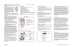
1
DIY Wireless Home Security
System Installation Guide
DIYSECURITY.CO.ZA
Contents
Introduction
Part 1: Planning .................................................................................................................................................. 3
Part 2: Control Panel Installation ........................................................................................................................ 3
Part 3: Control Panel Programming.................................................................................................................... 3
Part 4: Sensor Installation .................................................................................................................................. 3
Part 5: Test It ...................................................................................................................................................... 3
System Planning Diagram
Layout Diagram Example ................................................................................................................................... 4
Mounting Guidelines
Mounting Locations ............................................................................................................................................ 4
Magellan 6160 Console Radio Connection ........................................................................................................ 5
Pmd85 Outdoor 45Kg Pet Detector Installation Guide ....................................................................................... 6
Pmd75 45Kg Pet Detector Installation Guide ..................................................................................................... 7
Pmd1 18Kg Pet Detector Guide ......................................................................................................................... 8
Door Contact Installation Guide.......................................................................................................................... 9
DC Power Connect ........................................................................................................................................... 10
Wireless Limitations
Problems and Limitations ..................................................................................................................................11
Multipath Interference ........................................................................................................................................11
Electrical Interference ....................................................................................................................................... 12
Intermodulation ................................................................................................................................................. 13
RF Reflection and Attenuation .......................................................................................................................... 13
Refraction ......................................................................................................................................................... 14
Contact Details ............................................................................................................................................... 15
DIYSECURITY.CO.ZA
Introduction
Part 1: Planning
The first thing you’re going to want to do is figure out where you want to put the control panel. Typically, it’s
easiest for everybody to place it by the door you use most frequently you can always add extra keypads to your
Magellan system. You also need it to be near an electrical outlet (don’t choose one that’s switch-controlled). Don’t
pick a space where it’s easily viewed from the door or windows (you don’t want would-be burglars to be able to
scope out your system ahead of time). Please see System Planning Diagram and refer to Mounting Guide
Lines.pdf
Next, figure out where the best place is to put your security and fire sensors (ref. PMD85 Out Door 45kg Pet
Detector Installation Guide.pdf, PMD75 45kg Pet Detector Installation Guide.pdf PMD1 18kg Pet Detector
Guide.pdf). Also choose a location for the inside alarm siren if applicable. Don’t put it in an obvious location
(where the burglar could find and destroy it quickly), but don’t put it somewhere where the sound will be muffled
wither (i.e. closet, in upholstery).
Consider the most likely areas for a burglar to gain access eg. External doors, windows and gates etc. Using
magnetic door contacts, indoor infrared detectors and outdoor detectors, design a system that suites your
requirements. Range should be taken into account when using wireless systems see wireless limitations.pdf,
wireless range extenders can be added to the system.
Part 2: Control Panel Installation
Position the control panel at the height where it’s easy to access the keypad and read the display. Despite the
name “wireless home security system” there will indeed be a wire involved in connecting the control panel to the
outlet (ref. 6160 DC Power connect). To avoid tampering, you should run this wire through the wall (drill holes
behind the control panel and below the outlet, then connect the two). Magellan 6160 systems come with a
backup battery in case the plug is unplugged or the power goes out.
Installation could be a little more complicated if you are installing a monitored home security system. This will
involve also connecting a phone line. Depending on your experience, you may need to have the alarm company
technician help you with this stage. Consult the instructions that come with the system to complete installation of
the control panel. If a radio monitoring device is required this is obtainable from your monitoring company and
additional equipment may be required (see Magellan 6160 Console Radio Connection.pdf)
DIYSECURITY.CO.ZA
Part 3: Control Panel Programming
Magellan 6160 if purchased in a kit form, will be pre-programmed before delivery. You will be required to fill in the
system programming form and fax or email it back before we will be able to program. You can also program the
system easily at home by following the prompt on the key pad or by using the manual supplied. You’ll use the
control panel’s keypad to program the features of the alarm system. You are required to program your own
system code
Part 4: Sensor Installation
At this point, it’s time to install the alarm system’s sensors. You will have door sensors, window sensors and
infrared detectors to install (depending on the system). Door and window sensors will consist of a magnet and a
transmitter. The transmitter gets attached to the edge of the window frame or door while the magnet should be
attached to the window/door.
Most of our systems come with PIRS (Passive Infrared Motion Sensors), you can also buy smoke detectors,
broken-glass sensors, and other features. While these features are not typically difficult to install (a few screws,
some plastic hammer in anchors), it is important to place them carefully in order to achieve the best results.
Therefore, you should read the instructions that come with the Magellan 6160 system carefully.
We do supply glue with the kits in order to mount the detectors although it is recommended that the detectors and
sensors are attached with screws.
Part 5: Test It
The last step is to test your newly installed wireless home security system. Your Magellan 6160 comes with a
“test” mode (see manual supplied). Make sure to test all of the sensors and all of the functions of the security
system. If everything works, you’re done. You’ll want to test your system once a month or so to make sure
everything is in working order.
3
www.diysecurity.co.za
System Planning Diagram
Layout Diagram Example
Mounting Guidelines
DIYSECURITY.CO.ZA
Mounting Locations
•
•
•
•
•
Mounting locations affect the overall performance of the wireless system
In order to ensure the best possible signal reception, the following list of criteria should be respected whenever
possible
Select an installation site that is free of obstacles that reflect and absorb RF signals (RF reflection and attenuation),
and avoid installation near or in the path of strong RF fields (interference)
• One of the most basic obstacles is the ground and its relation to the receiver.
• The ground works as an RF noise generator, and also mirrors RF signals and sometimes even absorbs them
• Avoid mounting the receiver in the basement as the range of the receiver is reduced when mounted below
ground level
• If it is absolutely necessary that the receiver be mounted in the basement, ensure that it is mounted as high
and as close to the underside of the first floor as possible.
Select a site that is not susceptible to drastic temperature changes
• Mounting the receiver or transmitter in an area with drastic temperature changes can cause condensation and
moisture to collect in the receiver or transmitter
• Common problem areas include:
• Heater air duct
• Exterior doors
• Refrigerators and freezers
• Garage
Mount the wireless receiver as high and as central as possible to the proposed placement of the transmitters
• Ideally, the perfect antenna spreads its signal like a perfectly round circle. However, because of the transmitter’s physical construction (i.e. PCB, battery) it is more like a figure 8.
4
www.diysecurity.co.za
Figure 1
•
•
• The “dead spot”, or area where the RF signal is weak or non-existent, varies from one transmitter to the next
• Mounting the receiver as central as possible to the transmitters will help in avoiding the “dead spots”
Do not mount the transmitters too close to each other. Do not mount the transmitters too far or too close to the
receiver.
When RF devices are too close, strong RF signals can cause the devices to malfunction (Intermodulation)
• When a transmitter is mounted too far from the receiver, the RF signal is too weak to communicate effectively
or at all.
• As a general rule, when installing transmitters ensure that there is at least 30cm (1ft) between each transmitter,
and at least 1.5m (5ft) between each transmitter and the receiver
• The maximum distance that a transmitter can be from the receiver is dependant on the transmitter’s transmission range
DIYSECURITY.CO.ZA
Magellan 6160 Console Radio Connection
5
www.diysecurity.co.za
PMD85 Outdoor 45Kg Pet Detector Installation Guide
DIYSECURITY.CO.ZA
6
www.diysecurity.co.za
Figure / Figura / Figure 1
0*30'6(5,(6
B
7239,(:
R
Step
A
P
IW
P
IW
P
IW
P
IW
DIP
OFF
Switch 2 ON
6,'(9,(:
MGPMD85-TI05
Figure / Figura / Figure 2
PCB Setup / Configuración de la PCI / Configuration de la carte de circuits imprimés
The MG-PMD85 series features the following beam patterns:
Beam Pattern
MG-PMD85W
Pet Array beam pattern (see figure 3)
MG-PMD85L1
Horizontal Curtain beam pattern (see figure 4)
MG-PMD85L2
Vertical Curtain beam pattern (see figure 5)
- Detect LED
- LED de detección
- DEL de détection
B
B - Battery connector
- Conector de batería
- Connecteur de piles
A
C
Installation
After selecting the detector’s location, drill or punch out holes for the mounting screws
as shown in Figure 1.
Avoid placing the detector within proximity of sources of interference such as direct
sunlight, reflective surfaces and moving cars. Do not mount the detector near or on
metal, such as aluminum siding, as this may affect signal transmission.
The MG-PMD85 can also be mounted using the Paradox Swivel Mount Bracket
(469). The swivel mount may allow for easier mounting. If using the swivel
mount, it is recommended that you seal the space where the swivel mount is
connected to the back cover with some silicon or with a rubber gasket to ensure
that moisture does not enter the detector.
After you have installed the detector, ensure that the adjustable height markings on the
upper right of the PCB’s cover inside the unit match the installation height (see Figure
2). Any PCB adjustments should be followed by a walk-test to verify detector
coverage.
E
- Sensors / Sensores /
Capteurs
G
F
E
2.1m
C (7ft/pi)
D
- Anti-tamper switch
- Interruptor
antisabotaje
- Interrupteur de
sécurité
Ensure that the unit’s front and back cover are tightly joined together without
any spacing (around the rim of the unit) before tightening the screw, otherwise
the weatherproof casing may be compromised and moisture may enter the
unit.
Powering the Detector
1. Disconnect the battery cable from the battery connector of the PCB.
2. Remove the battery holder from the back cover and remove the old batteries.
3. Press and release the tamper switch to ensure that the unit has powered down.
Follow the steps outlined in “Powering the Detector” above.
Depending on the sensitivity setting, an alarm
condition can be generated between 0.25 sec.
(highest) and 2 sec. (lowest) after the actual
movement.
Viewing Sensitivity Settings
Remove the cover to view how many times the LED
flashes, then adjust the setting accordingly. The LED
flashes a consecutive amount of times to show the
setting. Thus if the sensitivity is set to 6, the LED
flashes 6 times.
3
Sensitivity
Figure / Figura / Figure 4
MG-PMD85L1 Horizontal Curtain Beam Pattern / Estructura de Tipo Cortina
Horizontal MG-PMD85L1 / Diagramme de lentilles Rideau horizontal MG-PMD85L1
7239,(:
Trimpot Turn clockwise
=Increase sensitivity
Turn counterclockwise =Decrease sensitivity
The sensitivity trimpot is fragile. Do not
overtorque.
U= default settings
DIP switches 3 and 4 are reserved for future use.
P
IW
Avoid bending, cutting
or altering the antenna
as this may affect signal
transmission.
An
gl
e
MG5000, MG5500, MG6030, MG-6060, MG-6130,
MG-6160 1759MG, MGRTX3, MG-RCV3
MG-PMD85W 90°
Sensor type:
Dual Element Infrared (x2)
Sensor geometry: Rectangular
MG-PMD85L1
85°
Operating temp: -35°C to +50°C (-31°F to
(Horizontal)
+122°F)
MG-PMD85L2
Power:
3 x “AA” alkaline batteries
5.64°
(Vertical)
RF frequency:
433* or 868**MHz
Lens:
2nd generation Fresnel lens,
LODIFF®, segments
Transmitter range: 35m (115ft) with MG-6160 / MG-6130
70m (230ft) with MG5000 / MG5500 / MG-RTX3
typical in a residential environment
Tamper switch:
Yes
Detection speed‡: 0.2m to 3.5m/s (0.6ft to 11.5ft/s)
Battery life†:
4 years
*
P
IW
- Sensitivity trimpot
- Potenciómetro
- Potentiomètre de
sensibilité
- Antenna / Antena /
Antenne
Technical Specifications
Compatibility:
P
IW
G
Evitar doblar, cortar o
alterar la antena pues
esto puede afectar la
Height Tab / Lengüeta de Altura /
transmisión de la señal.
Onglet de hauteur
Éviter de courber,
Align PCB height with the height tab of couper ou altérer
the back cover (see above).
l’antenne, car cela peut
nuire à l’émission des
Alinear la altura de la PCI con la
signaux.
lengüeta de altura de la cubierta
trasera (ver arriba).
Aligner la hauteur de la carte de
circuits imprimés avec l’onglet de
hauteur du couvercle arrière (voir cidessus).
Do not touch the sensor surface as this could result in a detector malfunction.
If necessary, clean the sensor surface using a soft cloth with pure alcohol.
Replacing the Batteries
- DIP switches
- Interruptores DIP
- Commutateurs DIP
P
IW
P
IW
D
DIYSECURITY.CO.ZA
1. Insert three “AA” batteries into the battery holder while verifying polarity (see
Figure 2).
2. Insert the battery holder into the back cover and affix the battery cable to the battery
connector on the PCB.
After connecting the battery cable, a power-up sequence will begin (lasting
between 10 to 30 seconds). During this time, the red LED will flash and the
detector will not detect an open zone or tamper.
F
P
IW
P
IW
P
IW
P
IW
6,'(9,(:
P
IW
P
IW
Figure / Figura / Figure 5
11m x 11m 2.1m
(35ft x 35ft) (7ft)
40kg
(90lbs)
11m x 11m 1.1m
(35ft x 35ft) (3.6ft)
Multi/large
pet
13m (43ft)
x 2 beams
N/A
2.1m
(7ft)
FCC ID: KDYMGPMD85 Canada: 2438A-MGPMD85
The MG-PMD85W complies with part 15 of the FCC rules. Operation is subject to the following two conditions: (1) This device
may not cause harmful interference, and (2) This device must accept any interference received, including interference that
may cause undesired operation.
** 868MHz (only) is not UL approved.
† Tested at 25°C. Battery life expectancy will vary according to the amount of traffic (movement) the detector has processed and
the temperature outdoors. A higher check-in time interval and higher traffic will lower battery life. In colder temperatures, the
capacity of alkaline batteries is reduced.
‡ The UL approved detection speed is 0.76m/s (2.5ft/s).
Walk-testing
To put the detector into Walk-test Mode, open and close the cover. At 20°C (68°F), at
the highest sensitivity setting and in Single Edge Processing mode, you should not be
able to cross more than one complete zone (consisting of 2 beams, left and right
sensor detecting elements) in the coverage area with any kind of movement; slow/fast
walking or running.
At the lowest sensitivity setting, the amount of movement required to generate an
alarm is doubled. The approximate width of a full beam at 11m (35ft) from the detector
is 1.8m (6ft). To walk-test, move across the detection path, not toward the detector.
After a power up, the detector will automatically enter Walk-Test mode for three
minutes.
Signal Strength Test
MG-PMD85L2 Vertical Curtain Beam Pattern/ Estructura de Tipo Cortina Vertical MGPMD85L2 / Diagramme de lentilles Rideau vertical MG-PMD85L2
7239,(:
In
H sta
ei ll
gh at
t ion
Pe
Im t
m
un
ity
Detector
A
C
ov
er
ag
e
Beam Patterns
=Dual edge
=Single edge U
The MG-PMD85 features adjustable sensitivity. Adjust
from 1 (lowest sensitivity) to 10 (highest sensitivity)U.
P
IW
English
= LED deactivated
= LED activated U
Single edge processing should be used in normal
environments with minimal sources of interference.
Dual Edge Processing provides better false alarm
rejection if the detector is placed near sources of
interference that can adversely affect it.
2
Signal
Processing
Mode
D -PCB screw
-Vis de la carte de circuits imprimés
-Tornillo de la PCI
B
Details
LED Feedback
On for 4 seconds:
Motion has been detected
Flash every 8 seconds: Low battery trouble (checked
every 12 hours)
Rapid Flash:
Sending signal to receiver
OFF
DIP
Switch 1 ON
C -Swivel mount bracket
-Soporte de montaje giratorio
-Support pivotant
A
DIP
1
LED Setting
B -Flat surface mount
-Montaje superficie plana
-Support pivotant
D
B
paradox.com
A -Corner mount
-Montaje en esquina
-Montage en coin
C
Instructions
Instrucciones
Printed in Canada - 06/2007
MG-PMD85W Pet Array Beam Pattern / Estructura de Tipo Paso de Mascotas MGPMD85W / Diagramme de lentilles Couloir pour animaux MG-PMD85W
B
A
A
Outdoor Digital Dual-Optic HighPerformance PIR V1.01
Detector Settings
Figure / Figura / Figure 3
Installation / Instalación / Installation
In order to verify the receiver’s reception of the motion detector’s signal, perform a
signal strength test before finalizing the installation of the MG-PMD85. Prior to
performing the test, make sure that the batteries have been inserted into the battery
holder to power the detector. Also verify that the motion detector has been assigned to
a zone. For more information on signal strength tests and zone programming, refer to
the appropriate receiver’s Reference & Installation Manual. If the transmission is
weak, just moving the detector by a few inches can greatly improve the reception. If
the signal is still weak, it is recommended that the detector be moved to another
location.
Alive Software
P
IW
P
IW
6,'(9,(:
P
IW
P
IW
P
IW
If the motion detector transmits two alarm signals (LED on for 4 seconds) within a five
minute period, the detector will fall into Energy Save mode where the detector will not
transmit any alarm signals for approximately 3 minutes. Due to the motion detector’s
Alive software, the red LED continues to flash to indicate a detection even when in
Energy Save mode. Once the three-minute Energy Save mode ends, the detector will
return to normal operation.
If the detector’s cover is removed and then replaced while in Energy Save
mode, the first detection will trigger an alarm signal.
© 2007 Paradox Security Systems Ltd. All rights reserved. Specifications may change without prior notice.
One or more of the following US patents may apply: 7046142, 6215399, 6111256, 6104319, 5920259,
5886632, 5721542, 5287111, 5119069, 5077549 and RE39406 and other pending patents may apply.
Canadian and international patents may also apply. LODIFF® lens: patent #4,787,722 (U.S.).
Digigard is a trademark or registered trademark of Paradox Security Systems Ltd. or its affiliates in Canada,
the United States and/or other countries.
LODIFF® is a registered trademark of Fresnel Technologies Inc.
Warranty: For complete warranty information on this product please refer to the Limited Warranty Statement
found on the website www.paradox.com/terms. Your use of the Paradox product signifies your acceptance
of all warranty terms and conditions.
PMD75 45Kg Pet Detector Installation Guide
DIYSECURITY.CO.ZA
7
www.diysecurity.co.za
MGPMD75-TI00
Digital Wireless Motion Detector
with Pet Immunity (MG-PMD75)
V2.0
With an OMN-RCV3 V2.0 or higher, the receiver automatically detects the check-in
time set in each of its assigned transmitters. As a result, the transmitters can have
different check-in times. With a previous version of the OMN-RCV3, the transmitter
check-in time needs to match the setting in the module.
may be used in conjunction with products not manufactured by Seller, Seller cannot guarantee the performance of the security system and shall not be
responsible for circumstances resulting from the product’s inability to operate. Seller obligation and liability under this warranty is expressly limited to repairing or
replacing, at Seller's option, any product not meeting the specifications. Returns must include proof of purchase and be within the warranty period. In no event
shall the Seller be liable to the buyer or any other person for any loss or damages whether direct or indirect or consequential or incidental, including without
limitation, any damages for lost profits stolen goods, or claims by any other party, caused by defective goods or otherwise arising from the improper, incorrect or
otherwise faulty installation or use of the merchandise sold.
With an OMN-RCV3 V2.0 or higher, if the check-in time setting is changed, power
down and then power up the receiver in order for the change to be recognized.
Notwithstanding the preceding paragraph, the Seller’s maximum liability will be strictly limited to the purchase price of the
defective product. Your use of this product signifies your acceptance of this warranty.
Powering the Detector
Replacing Batteries
1. Disconnect the battery connector from the PCB. Remove the battery holder and
remove the old batteries.
2. Press and release the anti-tamper switch to ensure that the unit has powered down.
3. Follow the steps outlined in “Powering the Detector”.
English
At the recommended height of 2.1m (7ft) ±10%, the MG-PMD75 motion detectors
provide full coverage from 1.5m (5ft) to 11m (35ft). The installation height is measured
from the center of the detector (Figure 1). All measurements shown in figures are
expressed in meters and (feet).
Avoid placing the detector within proximity of the following sources of interference:
reflective surfaces, direct air flow from vents, fans, windows, sources of steam/oil
vapor, infrared light sources and objects causing temperature changes such as
heaters, refrigerators and ovens.
Avoid bending, cutting or altering the antenna or mounting the detector near or on
metal as this may affect signal transmission.
Do not touch the sensor surface as this could result in a detector malfunction. If
necessary, clean the sensor surface using a soft cloth with pure alcohol.
The MG-PMD75 is designed for optimal performance at a height of 2.1m (7ft), but can
be installed lower or higher. After you have installed the detector, ensure that the
adjustable height markings on the right side of the PCB matches the tab inside the
back cover (see “H” in Figure 1). For example, if the detector is installed at a height of
2.1m (7ft), the PCB should then be adjusted to 2.1m (7ft) (Figure 1). Align the desired
marking (height) with the back cover’s plastic tab. If another installation height is called
for, readjust the PCB accordingly. Any PCB adjustments should be followed by a walktest of the protected area. Walk-testing verifies that the required coverage is in place.
LED Setting (J5)
2.1m
(7ft / pi.)
In High Shield mode, the amount of movement required to generate an alarm is doubled.
The approximate width of a full beam at 11m (35ft) from the detector is 1.8m (6ft). When
walk-testing, always move across the detection path and not toward the detector.
Walk-test mode is also activated for 3 minutes once the motion detector is powered
on.
In order to verify the receiver's reception of the motion detector’s signal, perform a
signal strength test before finalizing the installation of the motion detector. Prior to
performing the test, make sure the batteries have been inserted into the battery holder
to power the detector. Also verify that the motion detector has been assigned to a
zone. For more information on signal strength tests and zone programming, refer to
the appropriate receiver’s Reference and Installation Manual. If the transmission is
weak, relocating the transmitter by a few inches can greatly improve the reception.
Alive Software
If the motion detector transmits 2 alarm signals (LED on for 4 sec.) within a 5-minute
period, the detector falls into Energy Save mode where it won’t transmit any alarm
signals for approximately 3 minutes. Due to the motion detector’s Alive Software, the red
LED continues to flash to indicate a detection even when in Energy Save mode. Once
the 3-minute Energy Save mode ends, the motion detector returns to normal operation.
In Normal Shield mode, the detector is set for normal environments. In High Shield
mode, the detector is set for high-risk environments (potential interferences) and
therefore provides greatly increased false alarm immunity. However, response time
and detector speed may be slower. Refer to Table 1.
Single or Dual Edge Processing (J3)
This setting determines the DSP (Digital Signal Processing) operational mode of the
detector. Single Edge Processing mode should be used in normal environments with
minimal sources of interference. Dual Edge Processing mode provides better false
alarm rejection in the case where the detector is placed near sources of interference
that can adversely affect the motion detector. Refer to Table 1.
This jumper determines what model of wireless receiver the motion detector will be
communicating with, Omnia or Magellan. Refer to Table 1.
Check-in Supervision Timer (J1)
Jumper J1 sets the time interval in which the detector communicates a check-in signal
when used with Omnia or Spectra 1759EX (see Operating Mode). Refer to Table 1.
If the detector is used with Magellan (see Operating Mode), J1 is disabled and the
detector will regularly transmit a check-in signal to Magellan. The check-in supervision
time is set in the Magellan console.
3.1m
(10ft / pi.)
RF Frequency
Lens
Power
Transmitter Range
Anti-Tamper Switch
433* or 868**MHz
2nd generation Fresnel lens, LODIFF®, segments
3 X “AAA” alkaline batteries
35m (115ft) typical in a residential environment
yes
Lowest check-in setting: 3 years
Highest check-in setting: 1.5 years
Battery Life†
*
FCC ID: KDYOMNPMD75 Canada: 2438A-OMNPMD75
The MG-PMD75 complies with part 15 of the FCC rules. Operation is subject to the following two conditions: (1) This device may not cause harmful
interference, and (2) This device must accept any interference received, including interference that may cause undesired operation.
**
868MHz (only)
†
Battery life expectancy will vary according to the check-in time interval and the amount of traffic (movement) the detector has processed. A higher check-in
time interval and higher traffic will lower battery life.
compliant to all EU and EFTA countries except Greece according to RTT&E directives.
© 2002-2004 Paradox Security Systems Ltd. Specifications may change without prior notice.
Changes or modifications on equipment not expressly approved by Paradox Security Systems could void the user’s authority to operate the equipment. Omnia,
Spectra, Magellan and Shield are trademarks or registered trademarks of Paradox Security Systems Lts and its affiliates in Canada, the United Staes and other
countries. All rights reserved. One or more of the following US patents may apply: 6215399, 6111256, 5751803, 5721542, 5287111, 5119069, 5077549, 5920259,
5886632. Canadian and international patents may also apply. LODIFF® lens: patent #4,787,722 (U.S.). LODIFF® is a registered trademark of Fresnel
Technologies Inc.
Warranty
Paradox Security Systems Ltd. (“Seller”) warrants its products to be free from defects in materials and workmanship under normal use for a period of one year.
Except as specifically stated herein, all express or implied warranties whatsoever, statutory or otherwise, including without limitation, any implied warranty of
merchantability and fitness for a particular purpose, are expressly excluded. Because Seller does not install or connect the products and because the products
F
J3 J2 J1
B
- anti-tamper switch
- interrupteur de sécurité
- interruptor antisabotaje
C
- PCB height markings
- marques pour hauteur de
carte de circuits imprimés
- marcas de altura de PCI
D
- antenna/antenne/antena
A2
E
- sensors/capteurs/sensores
G
H
F
- LED/DEL/LED
G
- battery holder
- porte-piles
- compartimiento de batería
- el objetivo de la unidad está más
cerca; la distancia entre los haces es
más pequeña. La inmunidad contra
mascotas está comprometida.
- top battery
- pile du dessus
- batería de arriba
2.1m
(7ft /
7 pi)
H
- PCB height tab
- onglet pour hauteur de carte
de circuits imprimés
- lengüeta de altura de PCI
Table/Tableau/Tabla 1
LED Indicator / Voyant DEL / Indicador LED
C
- unit aims further, the gap between
beams is wider. Pet immunity is
compromised.
C
- l’unité capte plus loin et l’espace entre
les faisceaux est plus grand;
l’insensibilité aux animaux est
compromise.
1.1m
(4ft / pi.)
2.1m
(7ft /
7 pi)
- el objetivo de la unidad está más lejos,
la distancia entre haces es mayor. La
inmunidad contra mascotas está
comprometida.
J5
Figure 2 / Figura 2
90°
J4
Processing Type/Type de traitement/Tipo de Procesamiento
J2
9m
(30ft)
11m
(35ft)
3m 1.5m 0m 1.5m 3m
(10ft) (5ft) (0ft) (5ft) (10ft)
Figure 3 / Figura 3
A
- corner mount
- montage en coin
- montaje en esquina
A
B
B
C
A
A
B
B
OFF = Dual edge / divisé / polaridad doble
ON = Single edge / simple / polaridad simple U
B
- flat surface mount
- montage sur surface plane
- montaje en superficie plana
C
- PCB height tab
- onglet pour hauteur de carte de
circuits imprimés
- lengüeta de altura de PCI
OFF = Omnia / Spectra 1759EX
ON = Magellan U
Check-in Supervision Timer / Délai de supervision de présence / Tiempo de
Verificación de Prescencia
J1*
A
OFF = High Shield (low sensitivity) / Protection élevée (faible sensibilité)
Blindaje Superior (baja sensibilidad)
ON = Normal Shield (high sensitivity) / Protection normale (forte sensibilité)
Blindaje Normal (alta sensibilidad) U
Operating Mode / Mode de fonctionnement / Modo de Funcionamiento
2.1m
(7ft)
0m 1.5m 3m
6m
(0ft) (5ft) (10ft) (20ft)
OFF = disabled/désactivé/deshabilitado
ON = enabled/activé/habilitado U
Digital Shield (sensitivity) / Algorithme numérique Shield (sensibilité) / Digital
Shield (sensibilidad)
J3
Technical Specifications
Two dual opposed infrared sensors
11m x 11m (35ft x 35ft)
Up to 40kg (90lbs)
0.2m to 3.5m/sec. (0.6ft to 11.5ft/sec.)
2.1m to 2.7m (7ft to 9ft)
0°C to +50°C (+32°F to +122°F)
J5
J4
- l’unité capte plus près et l’espace
entre les faisceaux est plus petit;
l’insensibilité aux animaux est
compromise.
B
If the detector’s cover is removed and then replaced while in Energy Save mode, the
first detection will trigger an alarm signal.
Sensor Type
Coverage - 90° (standard)
Pet Immunity
Detector Speed
Installation Height
Operating Temperature
E
B
- unit aims closer, the gap
between beams is smaller. Pet
immunity is compromised.
Signal Strength Test
Digital Shield™ Setting (J4)
Operating Mode (J2)
2.1m
(7ft /
7 pi)
Open the cover in order to trigger the anti-tamper switch, then snap the cover back
into position. This will activate the motion detector’s walk-test mode for 3 minutes.
At 20°C (68°F), in Normal Shield (J4 = ON) mode and Single Edge Processing mode
(J3 = ON), you should not be able to cross more than one complete zone (consisting
of 2 beams, left and right sensor detecting elements) in the coverage area with any
kind of movement; slow/fast walking or running.
This setting enables or disables the red LED (Table 1). The red LED will illuminate for
a period of 4 seconds to indicate detected movement. The motion detector performs a
battery test every 12 hours. If the battery voltage is too low, the red LED will flash at 5second intervals and the motion detector will send a low battery signal to the receiver.
A trouble will then be generated and transmitted to the central monitoring station. The
red LED will flash rapidly when the motion detector transmits a signal to the receiver.
C
D
A
- optimum beam dispersion
- dispersion optimale du faisceau
- dispersión de haz óptima
A
Walk-testing
DIYSECURITY.CO.ZA
PCB Height Adjustment
B
Figure 1 / Figura 1
After connecting the battery connector, a power-up sequence will begin (lasting 10
to 30 seconds). During this time, the red LED will flash and the detector will not
detect an open zone or tamper.
780 Industriel Blvd., Saint-Eustache (Quebec) J7R 5V3 CANADA
Tel.: (450) 491-7444
Fax: (450) 491-2313
www.paradox.ca
A1, A2
- battery connector
- connecteur de piles
- conector de batería
BEWARE: Dealers, installers and/or others selling the product are not authorized to modify this warranty or make additional warranties that are binding on the
Seller.
1. Insert 3 “AAA” batteries into the battery holder while verifying polarity (Figure 4).
2. Insert the battery holder into the back cover and affix the battery connector to the
PCB (see “A1” and “A2” in Figure 4).
Instructions
Instrucciones
Figure 4 / Figura 4
A1
OFF = 12 minutes / minutos
ON = 12 hours / heures / horas U
U= default/par défaut/de fábrica
* = Omnia / Spectra 1759EX only
* = Omnia / Spectra 1759EX seulement
* = Sólo Omnia / Spectra 1759EX
After changing the jumper settings, snap on the cover to close the anti-tamper switch
or press and release the anti-tamper switch in order to save the changes.
Après la modification des réglages des cavaliers, remettre le couvercle en place pour
fermer l’interrupteur de sécurité ou enfoncer et relâcher ce dernier afin de
sauvegarder.
Después de cambiar la configuración de los puentes, encaje la cubierta en su lugar
para cerrar el interruptor antisabotaje o pulse y suelte el interruptor anti-sabotaje para
guardar los cambios.
PMD1 18Kg Pet Detector Guide
DIYSECURITY.CO.ZA
8
www.diysecurity.co.za
J1 OFF = 12 minutes
J1 ON = 12 hours (default)
Analog Single-Optic PIR
(18kg/40lbs Pet Immunity)
(MG-PMD1P)
V2.0
With an OMN-RCV3 V2.0 or higher, the receiver
automatically detects the check-in time set in each
of its assigned transmitters. As a result, the
transmitters can have different check-in times. With
a previous version of the OMN-RCV3, the
transmitter check-in time needs to match the
setting in the module.
With an OMN-RCV3 V2.0 or higher, if the check-in
time setting is changed, power down and then
power up the receiver in order for the change to be
recognized.
Operating Mode (J2)
MG-PMD1P can function on either the Magellan or
Omnia communication protocol. Set J2 according to
which receiver the MG-PMD1P will communicate with.
J2 OFF = Omnia / Spectra 1759EX
J2 ON = Magellan / Spectra 1759MG (default)
Instructions
Instrucciones
780 Industriel Blvd., Saint-Eustache (Quebec) J7R 5V3 CANADA
Tel.: (450) 491-7444
Fax: (450) 491-2313
www.paradox.ca
PRINTED IN CANADA - 06/2005
MGPMD1P-TI03
English
At the recommended installation height of 2.1m (7ft)
±10%, the MG-PMD1P will provide full coverage from
2m (6.5ft) to 15m (50ft), without any dead zones
(Figure 2).
Avoid placing the motion detector in proximity to
potential sources of interference such as: reflective
surfaces, direct air flow from vents, fans, windows,
sources of steam/oil vapor, and objects causing
temperature changes such as heaters, refrigerators,
ovens, and infrared light sources. Do not place objects
or furniture higher than 0.9m (3ft), which a pet can
climb onto (e.g. a cat on a couch), within 2.1m (7ft) of
the detector. In addition, do not aim the detector at a
stairway a pet may have access to.
Sensitivity Setting (J3)
J3 OFF = (High Sensitivity) In "1-3 mode", you should
not be able to cross more than one complete zone
(consisting of two beams - left and right sensor
detecting elements) in the coverage area with any kind
of movement. Use this setting for the majority of
installations (default).
J3 ON = (Low Sensitivity) In "2-6 mode", the amount of
movement required to generate an alarm is doubled.
The use of 2-6 mode is recommended in areas where
the incidence of false alarms may be greater.
Fast / Slow Mode (J4)
J4 OFF = "Slow Mode" is suggested in areas where the
incidence of false alarms may be greater.
J4 ON = "Fast Mode" is recommended for the majority
of installations (default).
Alive Software
To conserve the motion detector’s battery life, if the motion
detector transmits 2 open zone signals (LED on for 2 s)
within a 5-minute period, the detector will fall into Energy
Save Mode where it will not transmit any alarm signals for
approximately 3 minutes. Due to the motion detector’s
Alive Software, the red LED will continue to flash to indicate
a detection even when in Energy Save Mode. Once the
three-minute Energy Save Mode ends, the motion detector
returns to normal operation. If the detector’s cover is
removed and then replaced while in Energy Save Mode,
the first detection will trigger an alarm signal.
Avoid bending, cutting or altering the antenna or
mounting the detector near or on metal as this may
affect signal transmission.
LED ON / OFF (J5)
The MG-PMD1P is compatible with the following:
• Magellan All-In-One Wireless Console (MG-6060)
• Magellan Wireless Expansion Module (MG-RCV3)
• Omnia Wireless Expansion Module (OMN-RCV3)
• Spectra 1759EX control panel (Omnia protocol)
• Spectra 1759MG control panel (Magellan protocol)
Pet Immunity
An animal’s immunity to false alarms depends on its
size, temperature, and length of coat. Longer hair and
smaller size make an animal more likely to be immune,
while shorter hair and larger animals are more likely to
create a false alarm. When a higher level of immunity is
required, such as when animals are constantly in the
detection area, consider using our MG-PMD75 digital
dual-sensor high-performance PIR (40kg/90lbs true pet
immunity).
In order to verify the receiver's reception of the motion
detector’s signal, perform a signal strength test as
described in the receiver’s Reference and Installation
Manual before finalizing the installation of the motion
detector. Prior to performing the test, make sure the
batteries have been inserted into the battery
compartment to power the detector. Also verify that the
motion detector has been assigned to a zone according
to the instructions in the receiver’s Reference and
Installation Manual. If the transmission is weak,
relocating the transmitter by a few inches can greatly
improve the reception.
Technical Specifications
Sensor Type
Dual rectangular element
Coverage - 88.5° (standard) 11m x 11m (35ft x 35ft)
Center beams: 15m (50ft)
Installation Height
2.1m to 2.7m (7ft to 9ft)
Pet Immunity
18kg (40lbs)
Operating Temp.
0°C to 49°C (32°F to 120°F)
RF Frequency
433* or 868** MHz
Lens
2nd generation Fresnel lens,
LODIFF®, Pet Immune
Power
3 x “AA” Alkaline batteries
Transmitter Range
35m (115ft) with MG-6060; 70m
(230ft) with MG-RCV3; in a
typical residential environment
Anti-Tamper Switch
Yes
Up to 4 years
Battery Life†
The red LED will illuminate for a period of 2 seconds
whenever the motion detector detects any kind of
movement.
The MG-PMD1P pet immunity feature has not yet been
investigated by UL.
Check-in Supervision Time Value (J1)
Jumper J1 sets the time interval in which the detector
communicates a check-in signal when used with Omnia
or Spectra 1759EX (see Operating Mode).
If the detector is used with a Magellan receiver (see
Operating Mode), J1 is disabled and the detector will
regularly transmit a check-in signal to Magellan. The
check-in supervision time is set in the Magellan
receiver.
The motion detector performs a battery test every 12
hours. If the battery voltage drops below a certain level,
the red LED will flash at 5-second intervals and the
motion detector will send a low battery signal to the
receiver. A trouble will be generated and then
transmitted to the central monitoring station.
Signal Transmission
The red LED indicator light will blink rapidly when the
motion detector transmits a signal to the receiver.
Powering the Wireless Detector
Verifying proper polarity, insert three “AA” alkaline
batteries into the motion detector’s battery
compartment. To replace the batteries, remove the old
batteries, then press and release the anti-tamper switch
and wait 60 seconds in order to reinitialize the unit.
Insert new batteries while verifying proper polarity.
After inserting the batteries in the motion detector,
a power-up sequence will begin (lasting 10-30
seconds). During this time, the red LED will flash
and the detector will not detect an open zone or
tamper.
B
B
A
B
Flat Surface Mount
Montaje en superficie plana
Montage sur surface plane
A
B
UL approved detection speed 0.76m/s (30 in/s)
*
FCC ID: KDYOMNPMD1 IC: 2438A-104560
The MG-PMD1P complies with part 15 of the FCC rules. Operation is subject to the following two
conditions: (1) This device may not cause harmful interference, and (2) This device must accept any
interference received, including interference that may cause undesired operation.
**
868MHz (only)
compliant to all EU and EFTA countries except Greece according to
RTT&E directives. Please note that the 868MHz version is not UL approved.
†
Battery life expectancy will vary according to the check-in time interval and the amount of traffic
(movement) the detector has processed. A higher check-in time interval and higher traffic will lower
battery life.
Warranty
Paradox Security Systems Ltd. (“Seller”) warrants its products to be free from defects in materials and
workmanship under normal use for a period of one year. Except as specifically stated herein, all express or
implied warranties whatsoever, statutory or otherwise, including without limitation, any implied warranty of
merchantability and fitness for a particular purpose, are expressly excluded. Because Seller does not install or
connect the products and because the products may be used in conjunction with products not manufactured
by Seller, Seller cannot guarantee the performance of the security system and shall not be responsible for
circumstances resulting from the product’s inability to operate. Seller obligation and liability under this warranty
is expressly limited to repairing or replacing, at Seller's option, any product not meeting the specifications.
Returns must include proof of purchase and be within the warranty period. In no event shall the Seller be liable
to the buyer or any other person for any loss or damages whether direct or indirect or consequential or
incidental, including without limitation, any damages for lost profits stolen goods, or claims by any other party,
caused by defective goods or otherwise arising from the improper, incorrect or otherwise faulty installation or
use of the merchandise sold.
Notwithstanding the preceding paragraph, the Seller’s maximum liability will be strictly limited to the purchase
price of the defective product. Your use of this product signifies your acceptance of this warranty.
BEWARE: Dealers, installers and/or others selling the product are not authorized to modify this warranty
or make additional warranties that are binding on the Seller.
Note: The warranty does not apply to the alkaline batteries provided with the unit.
One of the following US patents may apply: 6215399, 6111256, 6104319, 5920259, 5886632, 5751803,
5721542, 5287111, 5119069 and 5077549. Canadian and international patents may also apply. LODIFF®
registered trademark of Fresnel Technologies Inc. Omnia, Magellan and Spectra are trademarks or
registered trademarks of Paradox Security Systems Ltd. and its affiliates in Canada, the United States and
other countries. All rights reserved. Specifications may change without prior notice.
© 2002-2005 Paradox Security Systems Ltd.
OFF = Disabled / deshabilitado / désactivé
ON = Enabled / habilitado / activé U
A
Fast - Slow Mode / Modo Rápido - Lento /
Mode rapide - lent
A
J4
B
OFF = Slow Mode / Mode Lento / Mode lent
ON = Fast Mode / Modo rápido / Mode rapide U
Sensitivity Setting / Configuración de la
Sensibilidad / Réglage de la sensibilité
Figure 2 / Figura 2
J3
11m x 11m
(35ft x 35ft)
Center beams:
15m (50ft)
11m x 11m
(35ft x 35ft)
Haces centrales:
15m (50ft)
OFF = High Sensitivity / Alta Sensibilidad /
Sensibilité élevée
ON = Low Sensitivity / Sensibilidad Lenta /
Sensibilité faible U
Operating Mode / Modo de funcionamiento /
Mode de fonctionnement
J2
11 m x 11 m
(35 pi x 35 pi)
faisceaux du centre :
15 m (50 pi)
OFF = Omnia / Spectra 1759EX
ON = Magellan / Spectra 1759MGU
Check-in Supervision Timer /
Tiempo de Verificación de Prescencia /
Délai de supervision de présence
J1* OFF = 12 minutes / minutos / minutes
ON =
Figure 3 / Figura 3
C
Alarm
After changing the jumper settings, replace the
cover to close the anti-tamper switch, or press and
release the anti-tamper switch, in order to save the
changes.
J5
Signal Strength Test
The red LED indicates the following:
J5 OFF = LED deactivated
J5 ON = LED activated (default)
A
Corner Mount
Montaje en esquina
Montage en coin
Open the cover in order to trigger the anti-tamper switch,
then snap the cover back into position. This will activate
the motion detector’s walk-test mode for 3 minutes. In
“fast” mode (J4 = ON), at 20°C, you should not be able
to cross more than one complete zone (consisting of two
beams left and right sensor detecting elements) in the
coverage area with any kind of movement; slow/fast
walking or running. In slow mode (J4 = OFF), the
amount of movement required to generate an alarm is
doubled. Walk-test mode is also activated for 3 minutes
once the motion detector is powered on.
Low Battery
Compatibility
LED Indicator / Indicador LED / Voyant DEL
Walk-testing
DIYSECURITY.CO.ZA
Do not touch the sensor surface; this could result
in a motion detector malfunction. If necessary,
clean the sensor surface with pure alcohol using a
soft cloth.
Table 1 / Tabla 1 / Tableau 1
Figure 1 / Figura 1
U= default / de fábrica / par défaut;
* = Omnia / Spectra 1759EX only;
* = Sólo Omnia / Spectra 1759EX;
* = Omnia / Spectra 1759EX seulement
A
F
J1
E
J2
B
D
C
Instalado a la altura recomendada de 2.1m (7ft) ±10%,
el MG-PMD1P brinda una cobertura total desde 2m
(6.5 ft) hasta 15m (50ft) sin niguna zona ciega (ver la
Figura 2).
Evitar ubicar el detector de movimiento cerca de
fuentes potenciales de interferencia como: superficies
reflectantes, corrientes de aire provenientes de
sistemas de ventilación, ventiladores, ventanas,
fuentes de vapor de agua / humo de aceite, y objetos
que provoquen cambios de temperatura como
aparatos de calefacción, refrigeradores, hornos y
fuentes de luces infrarrojas. No poner objetos o
muebles de más de 0.9m (3ft) de altura, sobre los
cuales pueda trepar una mascota (i.e. un gato sobre un
sofá), a 2.1m (7ft) o menos del detector. Además, no
dirigir el detector hacia una escalera por donde pueda
entrar una mascota.
No tocar la superficie del sensor pues puede
provocar un mal funcionamiento del detector. De
ser necesario, limpiar la superficie del sensor con
un paño delicado y alcohol puro.
Evitar doblar, cortar o alterar la antena o montar el
detector cerca de o sobre metal pues esto puede
afectar la transmisión de la señal.
Compatibilidad
El MG-PMD1P es compatible con:
• Consola Inalámbrica Todo en Uno Magellan (MG6060)
• Módulo de Expansión Inalámbrico Magellan (MGRCV3)
• Módulo de Expansión Inalámbrico Omnia (OMNRCV3)
• Central Spectra 1759EX (protocolo Omnia)
• Central Spectra 1759MG (protocolo Magellan)
Inmunidad contra Mascotas
J3
J4
A
- Anti-tamper Switch
- Interruptor antisabotaje
- Interrupteur de sécurité
12 hours / horas / heures U
Español
J5
B
- Antenna / Antena / Antenne
C
- Battery Compartment
- Compartimiento de bateria
- Compartiment à piles
D
- LED / LED / DEL
E
- Sensor / Sensor / Capteur
F
- PCB height markings
- Marcas de altura de PCI
- Marques pour hauteur de la carte de circuits imprimés
El que un animal no genere falsas alarmas depende de
su tamaño, temperatura, y del largo de su pelaje. El
pelo largo y el tamaño pequeño disminuyen la
generación de falsas alarmas, mientras que un animal
de pelo corto y gran tamaño tiene más posibilidades de
crear una falsa alarma. Para los casos en que sea
necesario un nivel de inmunidad superior, p.e.
animales que caminan constantemente en el área de
detección, considere usar nuestro doble sensor digital
de alto rendimiento MG-PMD75 (con inmunidad real
contra mascotas de hasta 40kg/90lbs de peso).
La característica de inmunidad contra mascotas del
MG-PMD1P aún no ha sido inspeccionada por UL.
Valor del Tiempo de Verificación de
Presencia (J1)
El Puente J1 establece el intervalo de tiempo en el cual
el detector transmitirá una señal de presencia cuando
se usa con Omnia o Spectra 1759EX (ver Modo de
Funcionamiento).
Si el detector es usado con un receptor Magellan (ver
Modo de Funcionamiento), el puente J1 es
deshabilitado y el detector transmitirá regularmente
una señal de presencia a Magellan. El tiempo de
verificación de presencia es definido en el receptor
Magellan.
J1 OFF = 12 minutos
J1 ON = 12 horas (de fábrica)
Con un OMN-RCV3 o posterior, el receptor
detecta automáticamente el tiempo de
supervisión de presencia definido en cada uno
de sus transmisores asignados. Por lo tanto, los
transmisores pueden tener tiempos de
verificación distintos. En una versión anterior
del OMN-RCV3, el tiempo de verificación de
presencia del transmisor debe coincidir con el
tiempo definido en el módulo.
Door Contact Installation Guide
DIYSECURITY.CO.ZA
9
www.diysecurity.co.za
JP2
JP1
Wireless 2-Zone Door
Contact
(Universal Transmitter)
MG-DCTXP2
V3.0
Do not cut, bend or
alter the antenna.
Avoid mounting
the door contact near or on
metal as this may affect
transmission.
Learn Mode
Learn Mode allows you to transmit the serial numbers of each
input. To enter Learn Mode, open the cover and wait until the
LED stops flashing.
Anti-Tamper
Switch
Serial Number
Visual
Confirmation
Press and release
the anti-tamper
switch once.
SN = Reed switch
(e.g. 240 000)
The LED will flash
once four times.
Press and release
the anti-tamper
switch twice within
one second.
SN+1 = Universal
transmitter input
(e.g. 240 001)
The LED will flash
twice rapidly four
times.
Español
El MG-DCTXP2 puede aceptar dos
entradas simultáneamente (entrada de
interruptor de lámina y universal).
Transmite dos números de serie diferentes
(NS), uno por cada entrada, los que son
siempre NS y NS+1(e.g. 240 000 & 240
001). Un interruptor u otro dispositivo de
seguridad puede ser conectado a los
terminales de entrada de transmisor
universal para obtener transmisión
inalámbrica del estado de abierto/cerrado
del dispositivo.
No se debe cortar,
doblar o alterar la
antena. Evitar
ubicar el contacto de
puerta cerca de o sobre
metal pues esto podría
afectar la transmisión
Ubicación y Montaje
JP1 ON
www.paradox.com
English
The MG-DCTXP2 can support two inputs
simultaneously (reed switch & universal
input). It transmits two different serial
numbers (SN), one for each input, which
are always SN and SN+1 (e.g. 240 000 &
240 001). A switch or other security device
can be connected to the universal
transmitter input terminals to provide
wireless transmission of the device's open/
closed status.
AAA
AAA
Printed in Canada - 12/2007
Normally Open
Reed Switch/Universal Input:
open = “zone open” signal
closed = “zone closed” signal
JP1 OFF Normally Closed
Reed Switch/Universal Input:
open = “zone closed” signal
closed = “zone open” signal
JP2
NOT USED
DIYSECURITY.CO.ZA
Location & Mounting
There should be at least 30cm (1ft) between
each transmitter and 1.5m (5ft) between the
transmitters and the receiver.
Testing the Unit
1. Perform a signal strength test before
finalizing installation. If the transmission
is weak, relocate the transmitter by a few
inches to improve reception.
2. Verify that the batteries are inserted
properly.
3. Assign the door contact to a Magellan
receiver.
4. Open and close the assigned door/
window to verify proper operation.
Powering the Unit
Verify proper polarity and insert two alkaline “AAA” batteries. After inserting batteries, a
power up sequence will begin (10-20 seconds) during which the door contact will not
detect an open zone or tamper.
Low Battery
The door contact performs a battery test every 12 hours. If the voltage is below 2.3V
after four consecutive battery tests (48 hrs.), the red LED will flash at 5 second intervals
and the MG-DCTXP2 will transmit a low battery signal.
Replacing the Batteries
1. Efectuar una prueba de fuerza de la
señal antes de terminar la instalación. Si
la transmisión es débil, mover el
transmisor tan sólo unos pocos
centímetros para mejorar la recepción.
2. Verificar si la batería ha sido insertada
correctamente.
3. Asignar el contacto de puerta a un
receptor Magellan.
4. Abrir y cerrar la puerta o ventana
asignada para comprobar el buen
funcionamiento.
El Modo de Aprendizaje permite transmitir el número de serie de
cada entrada. Para acceder al Modo de Aprendizaje, abrir la
cubierta del contacto y esperar que las luces LED dejen de
parpadear.
Interruptor
Antisabotaje
JP1 ON
JP2
Insertar dos baterías alcalinas “AAA”, verificando la correcta polaridad. Luego de haber
insertado las baterías, se inicia una secuencia de encendido (10 y 20 seg.) durante la cual
el contacto de puerta no detectará una zona abierta o un sabotaje.
Batería Baja
El contacto de puerta efectúa una prueba de batería cada 12 horas. Si el voltaje es menor
que 2.3V por cuatro pruebas de baterías consecutivas (48 horas), la luz LED roja parpadea
a intervalos de 5 segundos y el MG-DCTXP2 transmite una señal de batería baja.
Especificaciones Técnicas
MG/SP Series, MG-RTX3, and MG-RCV3: 60m (200ft)
Magellan Console: 30m (100ft)
Spectra 1759MG: 45m (150ft)
Yes
MG5000/MG5050, Any Spectra SP Series panel, MG-6130/MG-6160,
MG-RTX3, MG-6030/MG-6060, Spectra 1759MG, and MG-RCV3
11cm X 3.2cm X 2.5cm (4.4in X 1.3in X 1.0in)
0°C to 49°C (32°F to 120°F)
Anti-tamper switch
Compatibility
Dimensions
Operating temperature
Approvals
†
433MHz
868MHz
Up to three years**
SIN USAR
Encendido de la Unidad
Technical Specifications
Range (typical in a residential
environment)
Normalmente Abierto
Entrada Universal / de Interruptor de Lámina
abierto = señal de “zona abierta”
cerrado = señal de “zona cerrada”
JP1 OFF Normalmente Cerrado
Entrada Universal / de Interruptor de Lámina
abierto = señal de “zona cerrada”
cerrado = señal de “zona abierta”
Cambio de Baterías
One (high sensitivity) with a standard gap of 1cm (0.4”) from magnet
45 ms
433MHz or 868MHz
3.0Vdc (Two “AAA” Alkaline batteries)*
Confirmación
Visual
Pulsar y soltar dos veces SN+1 = Transmisor La luz LED
el interruptor antisabotaje universal
parpadea
al interior de un segundo. (e.g. 240 001)
rápidamente dos
veces en cuatro
ocasiones.
To replace batteries:
1. Remove the old batteries.
2. Press and release the anti-tamper switch several times.
3. Wait 60 seconds to reinitialize the unit.
Reed switch w/magnet
Input Response Time
RF frequency
Power
Battery life
Número de Serie
Puentes
Prueba de la Unidad
AAA
Jumpers
Debe haber una distancia de por lo menos
30cm (1ft) entre cada transmisor y 1.5m
(5ft) entre los transmisores y el receptor.
AAA
Instructions
Instrucciones
Modo de Aprendizaje
Pulsar y soltar una vez el SN = Interruptor de La luz LED
interruptor antisabotaje. laminá
parpadea cuatro
(e.g. 240 000)
veces.
JP2
JP1
MGDCTXP2-TI05
Para cambiar las baterías:
1. Sacar las baterías usadas.
2. Pulsar y soltar varias veces el interruptor anti-sabotaje.
3. Esperar 60 segundos para reinicializar la unidad..
Interruptor de lámina con imán
Tiempo de Repuesta de Entrada
Frecuencia RF
Alimentación
Vida útil de la batería
Alcance (típico en un ambiente
residencial)
Interruptor antisabotaje
Compatibilidad
Dimensiones
Temperatura de funcionamiento
Homologaciones† 433MHz
868MHz
Uno (de alta sensibilidad) con espacio estándar de 1cm (0.4”) del imán
45 ms
433MHz ó 868MHz
3.0Vcc (Dos baterías Alcalinas “AAA”)*
Hasta tres años**
Serie MG/SP, MG-RTX3, y MG-RCV3: 60m (200ft)
Consola Magellan: 30m (100ft)
Spectra 1759MG: 45m (150ft)
Sí
MG5000/MG5050, Cualquier central de la Serie Spectra SP, MG-6130/
MG-6160, MG-RTX3, MG-6030/MG-6060, Spectra 1759MG, y MGRCV3
11cm X 3.2cm X 2.5cm (4.4in X 1.3in X 1.0in)
0°C a 49°C (32°F a 120°F)
DC Power Connect
DIYSECURITY.CO.ZA
10
www.diysecurity.co.za
•
In extreme situations, the reflected RF wave (B) inverts and cancels out the direct path RF wave (A)
•
To remedy this, simply move the transmitter or receiver a few inches
DIYSECURITY.CO.ZA
Electrical Interference
•
•
•
•
•
•
•
Caused by the unintentional generation of RF due to an electrical spark, arc or discharge
Any wiring connected to the spark source conducts the RF and acts as a transmitting antenna
As a general rule, the noisier an electrical device is the potential it has of generating RF noise
Three types of electrical interference
RF noise from electrical equipment
RF noise generated by electronic devices
Interference from natural sources such as lightning
12
www.diysecurity.co.za
Possible sources of electrical interference:
•
•
•
•
•
•
•
•
•
•
TV or computer cathode ray tube (CRT) displays
Electric welders
Air conditioners
continue on following page.....
Brush-type motors
Electrical Interference
Relays and switches of all kinds
Arcing and corona discharge in power line insulators
Malfunctioning flourescent/neon lighting and automobile spark plugs
Light dimmers
Intermodulation
•
•
•
•
•
•
•
Occurs when a strong signal (i.e. communications tower), whose frequency is generally not near that of
the wireless receiver, overloads some circuit in the receiver As a result, the circuit generates harmonics of the
strong signal, which then combine in the receiver to create a new frequency
The newly created frequency, called an Intermodulation Product, interferes with the wireless
system in much the same way as other sources of interference
For example, mounting a transmitter too close to a receiver can cause intermodulation. The signal from
the transmitter is too strong due to its proximity to the receiver
RF Reflection and Attenuation
•
•
•
•
•
•
•
•
•
RF Reflection and Attenuation
Reflection: RF signals bounce off a reflective surfacE such as a wall or the ground
Attenuation: When RF signals pass through solid objects, some of the signal power is absorbed. Thisloss of RF
energy is called Attenuation, which varies depending on the structure of the object
An installation site’s physical construction and the obstacles on the site affect RF signals
Walls, doors, floors, elevator shafts, people and other obstacles offer varying degrees of attenuation and reflection
This causes the RF radiation pattern to be irregular and unpredictable
When an RF wave meets an obstacle, one of the following three phenomena occur:
Reflection
Reflection from walls, ceilings and floor surfaces can be partial or complete and cause multipath interference
DIYSECURITY.CO.ZA
13
www.diysecurity.co.za
Refraction
•
Occurs when an RF wave crosses a boundary from one medium to another (i.e. from air to water). A wave entering
a medium at an angle will change direction
•
Diffraction: It is the bending of RF waves around an object’s edge, such as a sharp corner or opening
DIYSECURITY.CO.ZA
•
•
•
•
•
•
•
•
•
Objects that reflect and attenuate RF signals include:
Metal objects
Objects with metal in them
Ground
Circuit breaker boxes
Trees: RF energy loss depends on the size and type of tree. Large trees with dense foliage create greater loss
Walls: Interior walls create less RF energy loss and exterior walls, especially those with stucco, create greater loss
Floors: Wood floors create less RF energy loss and concrete and steel floors create greater loss
Mirrored walls have very high RF energy loss
14
www.diysecurity.co.za
Contact Details
Tel: 011 462 7610
Mobile: +27 (82) 903 7156
Email: [email protected]
Website: www.diysecurity.co.za
DIYSECURITY.CO.ZA
15
www.diysecurity.co.za