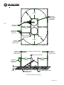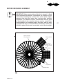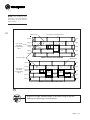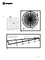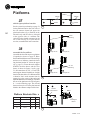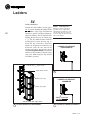
1
Ezee Dry
Bin Dryer
36' D i a m e t e r B a t c h / C o n t i n u o u s F l o w
CONSTRUCTION AND
OWNER’S MANUAL
P/N 015886
rev 2013-12-02
2
The Symbol shown below is used to call your attention to
instructions concerning your personal safety. Watch this
symbol - it points out important safety precautions. It means
“ATTENTION” - Become Alert! Your Personal Safety Is
Involved! Read the message that follows and be alert to the
possibility of personal injury or death.
Be Alert!
Your Personal Safety Is Involved
A copy of this manual should be available at all times to the owner/operator.
Additional copies may be requested from the company at the address shown
on the back cover. Please reference part number #015886 when requesting
additional copies.
Please Contact MFS/YORK/STORMOR or Your Dealer
If You Have Any Questions Concerning This Manual
Keep This Manual In A Safe Place Available For Future Reference
015886 5-02
PREFACE
You have purchased the finest roof dryer and grain storage bin manufactured
today. The following information is intended as a guide in caring for your
bin prior to construction, proper construction of your bin, and safe and proper
use of your bin once constructed.
Table of Contents
015886 5-02
A.
Warranty ....................................................................4
B.
Maintenance .............................................................5
C.
Important Safety Information...............................6
D.
Specifications ........................................................11
E.
Concrete and Site Location .............................. 15
F.
Foundation Plan ................................................... 17
G.
Important Pre-Assembly Info............................ 18
H.
Dryer Parts Identification .................................. 22
I.
Ezee
Dry Assembly
20
H
....................................................................................
1.
Sidewall Construction ................................ 24
2.
Dryer Assembly ............................................ 27
3.
Build the Roof ................................................ 37
4.
(Grain Band Layout) .................................... 45
5.
Install Chain Assemblies ........................... 46
6.
Continue Building the Sidewall .............. 48
7.
Platforms .......................................................... 50
8.
(Sidewall Layout for Doors) ..................... 53
9.
Doors ................................................................. 54
10.
(Installing the Final Stiffeners) ............... 55
11.
Bin Completion .............................................. 56
12.
Sidewall Gage Layout ............................. 59
13.
Finishing Construction ............................... 59
14.
Ladders ............................................................. 60
J.
Operation
................................................................. 64
K.
Pump Unit Assembly ........................................... 65
L.
Parts List and Numbers ..................................... 66
3
Warranty
Global Industries Inc. (the Company) makes the following warranty to the initial
retail purchaser of its products (the Customer).
MATERIALS and WORKMANSHIP:
The Company warrants products manufactured by it to be free from defects in
materials and workmanship in normal use and service for a period of five (5) years
after date of delivery to the Customer.
COMPANY’S OBLIGATION and
CUSTOMER’S EXCLUSIVE REMEDY:
The Company’s sole obligation and the Customer’s exclusive remedy under this
warranty is as follows:
If within five (5) years after delivery to the customer the product fails to function properly
due to a defect in either materials or workmanship, the Company will at its option, either
repair the defective part or replace the defective part with a new or reconditioned part.
Labor charges for removing defective parts and installing replacement parts, shipping
charges with respect to such parts, and applicable sales and other taxes, if any, shall
not be covered by this warranty.
CONDITIONS, LIMITATIONS, AND EXCLUSIONS:
There are no warranties or merchantability or fitness for a particular purpose
with respect to any product manufactured or sold by the Company. Motors provided
by the Company are in most instances warranted by the manufacturer thereof and
are not warranted by the Company. The Company shall not be responsible under
this warranty or otherwise for personal injury or for Incidental or Consequential
Damages, including, without limitation, loss of use and lost profits. This warranty
does not apply to defects or damages caused by misuse, improper maintenance,
or improper installation of the Company’s product or any equipment attached to or
used in connection with the Company’s product. The Company reserves the right
to make changes or improvements to its products without incurring any obligation
with respect to previously manufactured products. Field modification of this product
without the expressed written permission of the Company constitutes a misuse of
the product. The Company shall have no liability under this warranty until payment
in full for the product in question has been made by the customer. The foregoing
is the sole warranty made by the Company. No one is authorized to make other
warranties on behalf of the Company.
2013-12-02
GLOBAL INDUSTRIES, INC.
4
10239999F
Maintenance
Virtually the only thing that will limit the useful life of your bin is rust.
MFS/YORK/STORMOR has specified a galvanized coating on the steel used to
fabricate your bin that will give many years of service if properly maintained.
However, some rusting over a period of years can be expected with any galvanized
products exposed to the weather. We suggest the following:
1. Do not allow the galvanized surfaces of your bin to become cluttered
with grain or foreign material. As these organic materials deteriorate,
they produce acids that may cause immediate damage to the galvanized
coating. Clean off any such buildups immediately.
2. Check the horizontal surfaces of your bin for any rain water ponding. Dry
and correct the source of ponding immediately.
3. The useful life of bins installed in coastal or acid rain areas may be improved
through periodic rinsing of the exterior surfaces with fresh water.
4. After unloading your bin, any organic material clinging to the interior
walls or floor should be removed.
5. Any large areas of zinc oxidation, commonly called “white rust”, may
eventually lead to deterioration of the base steel itself exhibited by the formation
of normal “red rust”. Small areas of white rust may be periodically repaired
by steel brushing and touch up painting with a wash primer and enamel paint.
Large areas of white rust or any red rusted areas should be repaired by sanding
to base metal and painting with a quality zinc-rich paint.
Besides stopping the premature development of rust, other things you should
periodically check are:
1. Any obvious foundation settlements. Major settlement may cause structural
failure of your bin.
2. Deterioration or looseness of any bolts or fasteners.
3. Continued secure attachment of all sidewall and roof ladders.
4. Proper functioning and attachment of all bin openings such as roof caps.
Be sure all latches and hold down clips are used as intended.
5. Since your bin is equipped with a floor, periodically remove the fan
transition and check beneath the floor for the condition of the floor
supports, pests, or a buildup of dust or FM. Clean or repair as required.
6. MFS/YORK/STORMOR strongly suggests that any mechanical or electrical
auxiliary equipment installed in or on the bin be checked on a yearly basis by
a qualified service technician. Consult your dealer for this service as they
are well versed in the care and maintenance of this equipment.
015886 5-02
5
Important Safety Information
This MFS/YORK/STORMOR Construction/Safety Manual is written to assist
and instruct those who are responsible for the complete Ezee Dry assembly,
and for anyone using the Ezee Dry once assembled.
6
MFS/YORK/STORMOR assumes no liability with respect to proper
construction and inspection, assembly, or use of its products established under
applicable laws, all of which is the sole responsibility of the purchaser and
those doing the assembly work.
Appurtenances and the accessories manufactured by us for use with our products
conform only to applicable Federal or Safety Standards in effect at such time.
GENERAL SAFETY STATEMENT
Occupational safety is of prime concern to us at MFS/YORK/STORMOR. This
manual was written with the safety of the operator or others who come in
contact with the equipment as our prime concern. The manual presents day to day
work problems encountered by the operator and other personnel. We wrote this
manual to help you to better understand how to safely build and use this Ezee Dry.
It is your responsibility as an owner or operator or supervisor, to know what
specific requirements, precautions, and work hazards exist and to make these
known to all other personnel working with the equipment or in the area, so
that they too may take any necessary safety precautions that may be required.
Failure to read this Manual and its Safety Instructions by all personnel is a
misuse of the equipment. We want you as our partner in safety.
Watch For This Symbol! It Points Out Important Safety Precautions.
It Means “ATTENTION” - Become Alert! Your Safety Is Involved!
WORK AREA SAFETY STATEMENT
Under no circumstances should persons not involved in the operation be
allowed to trespass into or be present in the work area.
It shall be the duty of all operators to see that children and/or other persons stay
out of the work area! Trespass into the work area by anyone not involved in the
actual operations, or trespass into a hazard area by anyone, shall result in an
immediate shut down by the operator.
It shall be the responsibility of all operators to see that the work area has
secure footing and is clean and free of all debris and tools which might cause
accidental tripping and/or falling. It shall also be their responsibility to keep
the work area clean and orderly during the operation.
015886 5-02
OPERATOR QUALIFICATIONS
Operation of this unit shall be limited to competent and experienced persons. In
order to be qualified, he / she must also know and meet all other requirements,
such as, but not limited to, the following:
1. Some laws and regulations specify that no one under the age of 16 years
may operate power machinery. It is your responsibility to know what
these requirements are in your own area or situation.
2. Current OSHA regulations state in part: “At the time of initial assignment
and at least annually thereafter, the employer shall instruct every employee
in the safe operation and servicing of all equipment with which the
employee is, or will be involved” *
3. Unqualified persons are to stay out of the work area.
4. A person who has not read and understood all operating and safety
instructions is not qualified to operate the machine.
*
Federal Occupational Safety & Health Standards for Agriculture
Subpart D. Section 9128.57 (a) (6).
OSHA
OCCUPATIONAL SAFETY AND HEALTH ACT OF 1970
Certain purchasers of our products may be subject to the requirements and
standards of the William-Steiger Occupational Safety and Health Act of 1970,
which prescribes standards for use of appurtenances of our manufacture, such
as handrails, platforms, stairways, fixed ladders, ladder cages, and guard
rails. (Occupational Safety and Health Standards Section 1910.21 through
1910.32). Before installing these devices, familiarize yourself with the above
Federal Standards.
At the time of manufacture, these optional items conform to applicable
standards. MFS/YORK/STORMOR assumes no liability with respect to proper
construction, inspection, assembly, or use of its products under applicable
laws, all of which is the sole responsibility of the purchaser and those doing
the assembly work.
SAFETY AND OPERATIONAL DECALS
Safety decals as shown on page 9 are installed on your Ezee Dry bin in the
locations indicated. Be sure all of these decals are in their proper location on
the bin and are in good condition. Check all safety decals and replace any
that are worn, missing, or illegible. They may be ordered as any other part is
ordered. See your dealer for additional information or contact the factory
direct at the address listed on the back cover of this manual.
015886 5-02
7
ADDITIONAL SAFETY RECOMMENDATIONS
A. You may decide to buy and install “auxiliary equipment” made by other
manufacturers. MFS/YORK/STORMOR has no control over the design and
manufacture of this equipment. If you buy and install auxiliary equipment,
then at a minimum we suggest that you do the following:
8
1. Obtain, read, and understand the instructions and cautions of the
auxiliary equipment manufacturer. Be sure all equipment is installed
according to the manufacturers recommendations.
2. Check with MFS/YORK/STORMOR or your dealer to be sure that your bin
is designed to support any additional loads supplied by the auxiliary equipment.
3. Obtain any applicable safety decals from the manufacturer of the
auxiliary equipment and insure they are displayed in a visible location.
4. Review and understand the diagram on page 10 concerning minimum
conductor clearances for conveyors and electrical storage structures.
5. Make sure all electrical equipment is properly installed and grounded
by a qualified electrician.
6. Check availability and operation of electrical lockout and emergency
stop systems.
7. Be sure all guards or shields are securely in place.
8. Store all operations/maintenance manuals in a safe place available
for future use.
B. In this and other manuals, shields and guards may have been removed for
illustrative purposes. Do not operate the equipment without shields and guards in
place. Failure to heed this warning may result in serious personal injury or death.
C. The relatively closed environment of a grain bin may promote the presence
of toxic molds, hazardous dust, or a lack of oxygen. Never enter a bin without
proper respiration equipment and someone else present to watch you.
D. Heed the suffocation warning decal shown on page 9. Flowing or crusted
grain within a bin can cause a person to become buried and suffocate.
E. When climbing bin sidewall and roof ladders, take care not to fall into
or from the bin. Common sense dictates that such appurtenances should
not be used when conditions such as rain or wind preclude their safe use.
MFS/YORK/STORMOR strongly recommends that optional climbing
equipment be purchased to meet the current specifications set forth by
OSHA or ANSI whether the individual operator is required by law to do
so or not. A properly secured safety belt should be used at all times when
performing operations work or maintenance on the bin roof and sidewall.
F. Care must be taken to avoid entanglement in equipment installed in or on
the bin. Securely Lock out all power, be it electrical or PTO, prior to working
on or near such equipment.
G. Field modification of the bin or auxiliary equipment without the
authorization of the manufacturer may present unknown dangers to the
operator and must be avoided.
015886 5-02
Decal I.D. & Placement
9
If augers manufactured by others
are installed in conjunction with your
bin, we strongly recommend that
this or a similar decal be installed in
a visible location on that equipment
if not present.
Located on the inside of the manway lid and on the
inside of the outer door cover.
Located on the inside
at the outer door cover.
Located on the inner door panel.
CAUTION
THIS BIN IS LIMITED TO ONE OF THE FOLLOWING USAGES AS LISTED BELOW - IMPROPER USAGE WILL
VOID ANY STATED WARRANTY APPLICABLE TO THIS PRODUCT.
S - DESIGNATES STORAGE BIN:
D - DESIGNATES DRYING BIN
SITUATION
H - DESIGNATES HEAVY DUTY BIN
S
D
H
2,500
7,500
15,000
SUPLEMENTAL HEAT ALLOWED
NO
YES
YES
MAXIMUM AIR FLOW IN CUBIC FEET PER MINUTE PER
BUSHEL GRAIN
MAXIMUM UNLOAD RATE (Bushels per hour)
1/5
3
7
MAXIMUM ALLOWABLE MOISTURE CONTENT IN PERCENTAGE POINTS ABOVE USDA DRY GRAIN STANDARDS
3
15
Greater than 15
MAXIMUM LOAD/UNLOAD FREQUENCY PER YEAR
2
4
8
STIRRING DEVICES:
36’ DIAMETER AND SMALLER
42’ DIAMETER AND LARGER
NO
NO
YES
YES-2 Augers or less
YES
YES
CONICAL HOPPER UNDER BIN ALLOWED
NO
NO
YES
APPROVED FOR SEISMIC LOAD
NO
NO
YES
RECIRCULATING/CONTINUOUS FLOW DRYER ALLOWED
NO
NO
YES
SEE YOUR CONSTRUCTION/SAFETY MANUAL FOR STANDARD WARRANTY AND OTHER SPECIFICATIONS.
mfs018036
Put on sidewall sheet bundles before shipped.
015886 5-02
Your Ezee Dry bin has load carrying capabilities and restrictions that are equivalent
to those listed for the Drying Bin.
100' MIN.
100' MIN.
STORAGE
STRUCTURE(S)
(GEOMETRY
OPTIONAL)
10
CONVEYING
MACHINE
100'
MIN.
100'
MIN.
OVERHEAD
CONDUCTOR
AND POLE
UNDERGROUND
CONDUCTOR
100' MIN.
100' MIN.
LINE OF
OVERHEAD
CONDUCTORS
LINE OF
OVERHEAD
CONDUCTORS
NO OVERHEAD CONDUCTORS
LINE OF
OVERHEAD
CONDUCTORS
CONVEYING MACHINE
OVERHEAD
CONDUCTOR
AND POLE
8' MIN
100'
MIN
CLEARANCE
UNDERGROUND
CONDUCTOR
100'
MIN
CLEARANCE
STORAGE STRUCTURE(S)
Minimum conductor clearances
015886 5-02
Specifications
This bin is designed along guidelines which allow it to provide the owner
years of service provided it is not used for purposes for which it was not
intended. The sidewall gage specifications for your bin appear in the sidewall
sheet layout information on pages 26 and 59. The general material
specifications for your bin are as follows:
11
WALLS
All wall sheets are of corrugated, galvanized steel with 2.66" corrugation.
Wall sheets have .90 oz. per square foot zinc coating (G-90 designation).
2.66" corrugation sheets have 32" vertical coverage.
Horizontal coverage of wall sheets is 112 1/2".
All 5/16" bolts are electro-galvanized grade 8.2 with self-sealing injection
molded washers.
Sealer strip is provided to seal all vertical sidewall seams.
Base Sealer is provided to seal between the bin and the concrete foundation.
Anchor Bolts are standard with all Ezee Dry bins.
STANDARD ROOFS
All single span sheets are made of 22 gage galvanized steel and have a 36”
opening at the peak with a 2 1/4” rib height.
One manhole roof sheet is standard on each bin. A hinged lid is also included
with an opening size of 3.7 square feet.
A roof ladder from the eave to the peak and a roof safety ring is standard
with each bin.
Steep 32º roof slope.
There are 36 sheets per roof.
Roof sheets are attached to sidewalls with specially designed eave clips.
Loading:
Live Load - 25 pounds per square foot
Dead Load - 3 pounds per square foot
Wind Load - 20 pounds per square foot
015886 5-02
Concentrated Peak Loading:
2000 pounds
Specifications
(continued)
DOORS
On 2.66 corrugated bins, a single ring 32” door is standard on all sizes and a
two ring 64” walk door is available as an option.
12
The standard location of the one ring door is in the second ring from the bottom.
The standard location of the 64” door is in the second and third rings from the
bottom. See pages 53 and 54 for installation.
All 32” doors have two inner panels and an outer door cover and 64” doors
have three inner panels and an outer door cover.
DESIGN CRITERIA
Bins are designed to store flowable, noncorrosive material with 48 pound
bulk density (60 pound/bushel) maximum.
Bins are designed to be filled through the center roof opening only, and to be
emptied only from the center. Any off-center unloadings should be used only
for clean-out after discharge has been complete to the angle of repose.
Have your erector make all non-bin equipment in excess of the company’s
recommendations, like LEGS, WALK- WAYS, SPOUTING and CONVEYORS
self supporting.
Do not overfill the bin roof area during final storage. This prevents proper
air movement through roof vents and may also cause roof damage or failure.
Adequate ventilation area must be furnished to match the cubic foot per minute
output of the crop drying and aeration fan installed on the bin. A rule of
thumb would be, no more than 2000 cubic feet per minute per square foot
vent opening. When you run your fans, make sure your VENTS ARE OPEN
and kept clean of all debris and frozen matter. An aeration system can, without
proper management, create a greater load on a roof than equipment or snow
and can damage the bin roof
WARNING:
Installation of accessories or equipment in or on a grain bin that would
over stress the structure in any manner will void the Warranty. If you do
not have specific recommendations from MFS/YORK/STORMOR, where
additional loading is involved, please contact the Engineering Department of
MFS/YORK/STORMOR before installing any such appurtenances or equipment.
015886 5-02
Specifications
(continued)
Ezee Dry Bin Capacity Chart
36’ Ezee Dry Bin
No. of
Rings
Storage Capacity
Drying Batch
Capacity
7
9310
2100
8
11598
2100
9
13885
2100
10
16172
2100
11
18459
2100
1. Bin capacities are approximate figures. The capacities shown above are
based on 1.25 cubic feet per bushel and a compaction factor of 6% in
accordance with ASAE voluntary standards.
2. Capacities are in bushels calculated as follows:
Storage Capacity:
Grain loaded level 2 rings below the Ezee Dry plenum less 13” aeration floor.
Drying Batch Capacity:
The amount on the plenum floor during a batch drying cycle.
CAUTION
All galvanized steel stored in bundles is subject to oxidation, sometimes called
“white rust” when exposed to moisture from any source. Care should be taken
to protect sidewall sheets and roof sheets as much as possible. INSIDE
STORAGE IS ADVISABLE. When on the job site, sheets should be placed
on edge far enough apart to allow air to circulate freely.
015886 5-02
13
Specifications
(continued)
CHECK DELIVERY
Your bin has been carefully checked before shipment. However, you should check
your shipment upon arrival using the provided Packing List to insure it is complete.
SIDEWALL SHEET IDENTIFICATION
14
As an aid in identifying corrugated sheets on the packing list a series of codes are
used in the description. Typically the description begins with “COR SHT XXYYZ ....” Where XX is the diameter of the bin; YY is the gage; and Z is one or
more alpha numeric code designations. The codes used are as follows:
5 = Half sheet for entrance collar
6 = Door sheet for double punched sheets
7 = Door sheets for single punched sheets
E = Sidewall sheet punched for Ezee Dry Stiffener
F = Sidewall sheet punched for flashing
K = Tension sheet / Purlin Attachment
N = Ezee Dry fan entrance sheet
P = Double punched sidewall sheet
T = Transition sheet
Examples:
COR SHT 18-17EF is an 18’ diameter sheet punched for Ezee Dry stiffeners
and flashing.
COR SHT 36-10K is a 36’ diameter sheet punched for Ezee Dry purlins.
TORQUE
Torque specifications for the fasteners that bolt your bin together are listed below.
Have your contractor demonstrate that he/she is giving you the correct torque.
Bolt Size
Torque (ft/lbs)
5/16" Grade 8.2
25
3/8" Grade 5
31
When you load or unload grain, always do it from the center. This creates an
even load on the structure. Only use your intermediate sumps for clean-up. Offcenter loading and unloading creates excessive stresses and can cause a failure.
All bins should be filled at the center of the peak ring with an auger or spout
of adequate length to allow grain to drop straight down into the bin.
Do not cut openings in bins. This reduces the structural strength of the unit
and can cause partial or complete failure.
015886 5-02
Concrete and Site Location
LOCATION OF BIN SITE
Check your site locations for possible problems with the following:
1. High wind or Snow load area
2. Waterways and run off
3. Poor soil conditions/soil problems
4. Local codes/permits 7. Railroads
5. Power lines
8. Seismic load
6. Highways
9. Hopper Bins
CHOOSING A BIN SITE
Consideration should be given to convenience in loading and unloading and accessibility
to existing and planned facilities. The site should be level, on firm soil, with adequate
drainage. Any fill used in leveling the site MUST BE well compacted to prevent
uneven settling from weight of the foundation, bin and contents. After the site is
completely level, use 1” to 2” of fill sand to act as a cushion under the concrete slab.
Standard foundation drawings and specs are furnished by MFS/YORK/STORMOR
showing soil bearing pressures required. It is the obligation of the purchaser
to obtain a soil bearing test and ascertain that the foundation has sufficient
strength for a capacity filled bin. Unless the finished foundation is level and
true, and the site properly graded for water drainage, failure of the foundation
could result. This is not covered by the MFS/YORK/STORMOR warranty.
At the time your soil is being compacted and the foundation is being poured, make sure
that the work is being done in exact accordance with your soil engineer’s specifications.
Remember - if your soil isn’t right, your foundation could TIP AND CRACK - if your
foundation isn’t right, your bin could fail. The foundation drawings on the following
pages are intended as a guide only and are not to be interpreted as “firm” instruction. If
at a later date, the bin is increased in height, the foundation may not be adequate.
Anchor bolts should be to specifications and be set when pouring the foundation
as improper anchoring will give you a WEAK structure.
The bin is ROUND and to keep it round, the anchor bolts should follow a
SCRIBED CIRCLE with the correct chord dimensions between the anchor bolts.
The base ring of the bin must rest firmly on the foundation with absolutely no overhang.
1. Lay out the foundation by driving a small pipe to mark the center
of the pad. The top of the pipe should be the height of the foundation.
2. Using the pipe for a center pivot, you can use a chain with a
sharp stake attached to the outer end to scribe on the ground the
foundation diameter. (A board may be used instead of the chain.)
3. After pouring the concrete, and while it is still soft, locate your
anchor bolts. Use the center pipe and chain again to mark the
correct diameter to set the anchor bolts. Use a measured chain
(or chord) to get the correct spacing between holes.
015886 5-02
15
IMPORTANT: Develop a layout plan of the bin, bin accessories,
and auxiliary equipment and then build the bin foundation in
proper accordance with the layout plan.
FOUNDATION NOTES:
1. The foundation site should be well drained and free of vegetation and/or debris.
2. Foundation(s) should be on undisturbed soil or engineered compacted backfill.
16
3. A soil and foundation (Geotechnical) investigation should be conducted
for each site to confirm the soil bearing capacity. Foundation Design is
based on an allowable soil bearing capacity of 3,500 psf.
4. The concrete shall have a minimum compressive strength of 3,000 psi. at 28 days.
5. Concrete should be allowed to cure 7 days before beginning the tank assembly
and 28 days before filling the bin.
6. Concrete should be kept level to ±1/8" in 10' and 1/2" across the diameter.
High spots or debris should be removed prior to setting the bin.
7. Anchor bolts need to be properly located based on the table, found on page
17 of this manual, in order to keep the tank round.
8. All concrete reinforcing rod shall conform to ASTM A615, Grade 60.
9. Rebar should lap a distance equal to (24 * Rebar Dia.). Minimum allowable
lap is 18"- i.e: #6 Rebar has a diameter of 6/8" =.75" * 24=18" or an 18" lap.
Estimates for Rebar do NOT include allowances for the lap.
10. Foundation details in this manual are to be considered general in nature and are
intended only as a guide. It is the owner’s responsibility to provide an appropriate site
and foundation design for the adequate support of the grain bin. MFS/YORK/STORMOR
assumes no responsibility for results arising from these suggestions.
11. The detail below depicts a typical support pad for the aeration pad at the base
of the bin. The dimensions should work for most applications, but may vary
depending on the manufacturer of the fan and transition.
pad is to be a minimum of 24” wide
aeration fan
wire
mesh
4”
33”
a
30”
TYPICAL AERATION FAN FOUNDATION PLAN
015886 5-02
FOUNDATION PLAN AND SPECIFICATIONS
G
F
Foundation Plan
A
A.
DI
E
Note: 24 Anchor bolts on the outside
of the bin; 12 on the inside.
RA
RAD
D.
C
17
Flat Slab
.B
A
1/2” x 10” anchor bolts
6 x 6 x 10/10 wire mesh
3”
4”
sandfill
1 1/2”
D
(2) 1/2” dia. reinf. bars
3”
Flat Slab / Ring Wall Section
3”
3”
W
Bin Dimension
dia A
Typical 36' Ezee
Dry Bins
37' 3"
radius B radius C
D
E
F
G
W
18' - 0 3/4"
18"
9' - 1 3/4"
2' - 4 9/32"
4' - 8 19/32"
20"
17'- 8 1/16"
Number of
Anchor Bolts
Wire Mesh
Square Foot
Concrete
Cubic Yards
Reinforcing
Rod Lin. Foot
Number and
Size of Rod
36
1060
21 1/2
228
2 - #4
015886 5-02
Important Pre-assembly Info
SIDEWALL SHEET IDENTIFICATION:
The bin wall sheets are color coded on the end of the sheets for easy reference as follows:
18
Red
Blue/Yellow
Yellow
-
17 Gage
15 Gage
14 Gage
Black
Orange
Brown
-
12 Gage
11 Gage
10 Gage
To determine the number of sheets per ring, divide the bin diameter by three:
(ie: 36’ diameter bin divided by 3 = 12 sheets per ring.) Note: there are 36
roof sheets.
BIN HARDWARE AND WHERE IT IS USED:
#12 x 3/4” self drilling screw Used to attach the flashing sealer to the flashing.
1/4” x 3/4” bolts and flange nuts Used to bolt the dump hoppers to the plenum sheets.
Used to bolt the dump chutes to the dump hoppers (w/ 2 nuts).
5/16” x 1” bin bolts with seal washer and nuts Used in bin sidewall sheets and roof sheets.
Used around the door.
Used on the stiffeners.
Used at the door and step across platforms.
Used at the perforated and 10 gage skirts.
Used at the grain bands.
Used at the plenum sheets.
5/16” x 1 - 1/4” bin bolts with seal washers and nuts Used to bolt the bottom sidewall sheet to the base angle.
Used to bolt the purlin mounting angle to the sidewall.
5/16” x 2 3/4” bolts and nuts Used to bolt the plenum sheets to the plenum rafters at the grain band posts.
5/16” x 1” carriage bolts
Used to bolt the stiffeners together
5/16” flange nuts Used under all roof ribs and at plenum sheets.
Used at the perforated roof flashing.
Used at the grain bands.
Used at the stiffeners.
015886 5-02
Bin Hardware, continued
3/8” x 1” hex bolts, flat washers and nuts Used to assemble the fan platform.
Used at the winch on batch units.
1/2” x 1 -1/2” hex bolts, flat washers and nuts Used to bolt the intermediate purlins to the purlin mounting angles.
1/2” x 2” hex bolts, lock washers and nuts Used at the pulleys.
1/2” x 10” anchor bolts, washers and nuts Used to secure the bin to the foundation.
3/4” x 1 - 1/2” hex bolts, nuts Used to bolt the main purlins to the center collar and top stiffener.
Sealer tape Used on bin wall seams (one strip vertically and 6-12” horizontally).
Used both vertically and horizontally around door frame.
Roof eave clip Attaches the top ring of the sidewall sheets (place on the outside). The
top set of holes puts the roof in a lowered position for a storage application
and the bottom set puts the roof in a raised position to facilitate drying.
Roof cap hardware Roof cap slide rod bracket.
Roof cap hold down bracket.
Roof cap slide rod tab.
Roof manhole hardware Manhole hinge.
Manhole hinge bracket.
Manhole latch catch.
Manhole latch side.
Manhole latch bushing.
Door hardware Outer door clip.
Striker plate.
Door T-handle.
#8 x 3/8” screw.
#8 external tooth lock washer.
#8 - 32” hex nut.
1/4” x 1/2” hex bolt and flange nuts.
UNDER NO CIRCUMSTANCES SHALL ANY OTHER BOLT
BE SUBSTITUTED FOR THOSE SUPPLIED BY
MFS/YORK/STORMOR
015886 5-02
19
Ezee Dry Assembly
GENERAL ASSEMBLY INSTRUCTIONS
1. Complete the foundation. See the foundation section earlier in this manual.
2. Set the sidewall sheets out near the pad in preparation for assembly.
3. Plan for the ladder location.
20
4. Bolt together the top three rings of the bin.
5. Connect the top 10 gage z-bar stiffeners to the vertical seams of the
second sidewall ring (10 gage).
6. Using scaffolding or a stand, support the center ring assembly at the
proper height.
Assembly
7. Install the main trusses.
8. Add the stiffener tie rods.
9. Attach the jack beams between all main trusses.
10. Fasten the mounting brackets to the sidewall and bolt the intermediate
purlins to the mounting brackets.
NOTE: Look over the ladders
sections of this manual on
pages 42 - 43 and 60 - 63
before building the bin. It
offers important information
for planning the bin’s layout
and construction.
11. Install 10 gage skirt sections at the upper bottom side of the main trusses.
12. Secure the pulley angle to the center collar.
13. Connect the cross braces to the vertical angles of the main trusses.
14. Attach the dump hoppers, dump necks, and flashing to the perforated roof sheets.
15. Add the perforated roof sheet assemblies to the structure.
16. Bolt on the flashing between perforated roof sheets and the sidewall.
17. Attach the upper perforated skirt and center cone to the assembly.
18. Install the eave clips and support the peak ring on a stand at the proper height.
19. Fasten on the roof sheets, complete the roof, and assemble the manway door.
20. Assemble the grain band rings.
21. Attach the 68’ cables and the chains to the center chain disks.
22. Build on the fan platform(s).
23. Complete the sidewall, adding the z-bar stiffeners as construction progresses.
24. Install the base angle and secure the bin to the anchor bolts.
25. Assemble the hydraulic pump unit if the bin comes equipped with one.
26. Add any other optional equipment included with the bin and finish construction.
015886 5-02
BEFORE BEGINNING ASSEMBLY
IMPORTANT: Before construction of the bin is started: 1) Read
and understand this manual. 2) Determine the locations for all
accessories including the: access door, anchor bolts, ladder,
manway, side draw, roof steps, fans, and any other auxiliary
equipment. 3) In addition to these, consideration must be given
to the location of the: electrical and gas service, control unit,
winch/hydraulic unit, unloading auger, entry door, and any other
equipment that may be involved. Please note that the control unit
should be placed on the north or east side, out of direct sunlight.
space roof vents
evenly around bin
2nd fan platform
step across
platform when 2
fan units are used
fan platform
door platform
outside ladder
a
015886 5-02
BASIC PLAN VIEW OF THE 36’ EZEE DRY
21
Parts Identification
center collar
DRYER STRUCTURE
truss
22
cross braces
NOTE:
Refer to pages 66 - 69
for all part numbers.
jack beam
mounting angle
spacer
truss
long intermediate
purlin
short intermediate purlin
stiffener tie rod
top 10 gage z-bar stiffener
015886 5-02
DRYER FLOOR ASSEMBLY
hanger bracket for
inlet funnel
perforated band clip
ezee dry inlet funnel
perforated grain band
cone
perforated purlin skirt
narrow grain band
center collar
grain band post
truss skirt
grain band
pulley bracket
pulley mounting angle
plenum sheet
center chain disk
flashing sealer
truss
flashing
dump hopper
dump chute
015886 5-02
23
Sidewall Construction
IMPORTANT!
sidewall sheet
Instructions to follow throughout
the building of the sidewall
24
1. All sidewall sheets are color
coded per the table on page 18
for ease of construction.
sealer tape
6” - 12”
2. See the sidewall layout sheet
table on page 59 for sidewall
sheet gage and placement.
3. Always overlap the sidewall
sheets in the same direction
as shown (fig. c).
a
4. Use one row of sealer tape at all
vertical joints and horizontally
for 6-12” from the end of each
sheet (fig. a). Wipe sheets clean
before applying the tape.
outside of bin
5. Bolt sidewall sheets together with
the bolt head and seal washer to
the outside of the bin and the nut
to the inside. At Stiffener
locations the bolt direction is as
indicated in fig. b on page 27.
6. The sheets should be
staggered in halves. The
halves measure ~56 1/4”.
SEALER TAPE AT SIDEWALL SEAMS
upper panel
5/16” hex nut
5/16” bin bolt
w/seal washer
inside of bin
lower panel
b
7. The top sidewall ring is hole
punched differently. It is punched
for the roof and does not have
any stiffener hole punching.
HORIZONTAL SHEET SEAM
overlap
8. The second ring is also punched
differently for the dryer
assembly (fig. a, page 26).
9. At horizontal seams, bolt lower
sheets to the inside of upper
sheets (fig. b).
sidewall sheet
c
SHEET OVERLAP ONE DIRECTION ONLY
015886 5-02
no stiffener hole punching on the 1st ring
dryer assembly hole
punching on the 2nd ring
17 gage
d
10 gage
BUILD THE TOP SIDEWALL RING
e
ADD THE SECOND RING
1
set out bin sidewall sheets on the pad
one fan entrance
door
Sort the sidewall sheets by gage
according to the color code and
layout table (page 59). Stand the
sidewall sheets on edge in the order
in which they will be used on the bin
pad near the location where the
sidewall will be built.
15 gage
f
FOR BINS WITH ONE FAN ENTRANCE
2
begin sidewall assembly
two fan entrances
door
15 gage
g
015886 5-02
FOR BINS WITH TWO FAN ENTRANCES
Build the top three sidewall rings (fig.s
d-g and fig. a, page 26). Refer to the
sidewall layout sheet table on page 59.
Make sure to use the proper number
and style of sheets so the diameter of
the bin is correct. For Ezee Dry bin
door and fan entrance space locations
refer to figures f and g. At the stiffener
locations install 5/16” x 1” bin bolts
in the “inside corrugation valleys” of
the vertical sheet seams at this time
(see fig. b on page 27). Stiffener bolts
will be added later in the “inside hill”
holes of the sheets.
25
NOTE:
After building the dryer
a s s e m b l y, f o l l o w t h e s i d e w a l l
layout below to install fans and
doors correctly.
26
3 1/8” spacing for roof attachments
flashing holes
rows of holes
for stiffeners
(ring built during
step 2)
top ring
17 ga
2nd ring
10 ga
3rd ring
door
15 ga
fan
entrance
4rth ring
17 ga
58”
5th ring
15 ga
SHEET LAYOUT WITH ONE FAN
ring built in step 2
flashing holes
rows of holes
for stiffeners
(ring built during
step 2)
top ring
17 ga
2nd ring
10 ga
3rd ring
4rth ring
door
fan
entrance
58”
15 ga
fan
entrance
58”
17 ga
58”
5th ring
15 ga
SHEET LAYOUT WITH TWO FANS
a
UPPER SIDEWALL LAYOUT SHOWING DOOR AND FAN ENTRANCE LOCATIONS
Align the 10 gage sidewall sheets in the second ring so that the
flashing hole punching is toward the top.
015886 5-02
Dryer Assembly
NOTE:
Use 5/16” flange nuts at
all stiffener locations on the side
of the stiffeners.
NOTE: The two lower holes in the
upper stiffener are for the tie rods.
3
fasten the top stiffeners
Bolt the twelve top 10 gage z-bar stiffeners
to the sidewall at the vertical seams of the
10 gage sidewall ring as shown (fig. b).
The top z - bar stiffener is 42 1/8” long.
standard 5/16” nut
outside
10 gage sidewall
sheets (2nd ring)
inside
27
4
holes for
3/4” main
purlin bolts
with nuts
install the first truss
Set the center collar in the bin’s center
(fig. a, page 28) at the height shown
(fig. c). Use a center jack platform. The
center collar should be oriented so that
the pulley mounting angle attachments
are on the bottom. Insert a bolt through
the first truss and the stiffener using either
of the two top holes in the stiffener and
truss (refer to fig. b, page 28). (The lower
two holes are for stiffener tie rods.) Bring
the top of the truss into position next its
corresponding flange on the center collar.
Insert a bolt through the flange and the
truss to hold the truss in place and then
install the rest of the bolts.
14 21/32”
holes for
tie rods
vertical
seam
“inside
corrugation valleys”
5/16” flange
nuts used at
stiffeners
5/16” bin bolt w/seal
washer, typical
top 10 gage
z-bar stiffener
15 gage
sidewall sheet
b
TOP STIFFENER ATTACHMENT
center collar
truss
jack beam
sidewall
14’ - 3 3/8”
top z-bar stiffener
c
HEIGHT OF CENTER COLLAR
015886 5-02
center collar
90º
trusses
13/16” holes for 3/4” bolts with nuts
sidewall
sidewall
28
a
ATTACH THE FIRST FOUR TRUSSES
5
install the trusses
center collar
Bolt the first four trusses on at right
angles around the bin to stabilize the
assembly (fig.s a and b) and then finish
installing the rest of the trusses.
truss
13/16” holes for 3/4” x 9’ 5” rods
top 10 gage z-bar stiffener
6
connect stiffener tie rods to stiffeners
b
TRUSS TOP AND BOTTOM CONNECTION DETAIL
Install the stiffener tie rods between the
trusses alternating the holes for each rod (fig.
c and e, page 29). Thread a nut on to each
end of the rod. Insert the rod through the
holes in the stiffener and truss. Thread a
2nd nut on the end of the rod and snug this
nut up to put tension on the rod. Install all
rods, then securely tighten all nuts (fig. d).
tie rod to outer hole
tie rod to inner hole
truss
top stiffener
truss
3/4” nut, typical
tie rod
tie rod
c
PROPER TIE ROD INSTALLATION
top
stiffener
d
TIE ROD, STIFFENER TRUSS CONNECTION
015886 5-02
tie rod
truss
stiffener
3/4” nut
29
7
sidewall
attach jack beams between trusses
Bolt on jack beams between all main
trusses (fig. f and fig. a, page 30).
Leave the bolts loose at first to insure
an easy installation.
e
STIFFENER AND TIE ROD ARRANGEMENT FROM ABOVE
hole at the top
of jack beam
jack beam
jack beam
bolt plate
jack beam angle
on king post
jack beam
king post
truss
NOTE: use proper bolts
and nuts as shown on
the next page.
f
015886 5-02
JACK BEAM TO TRUSS CONNECTION
1/2” x 1 1/2” bolt
with (2) nuts
truss
jack beam angle
on king post
jack beam
jack beam
3/4” x 1 1/2” bolt
king post
jack beam bolt plate
3/4” nut
slip
connection
30
a
truss
JACK BEAM TO TRUSS CONNECTION FROM ABOVE
8
flashing holes
properly secure bolts on jack beams
After setting the last jack beam into
place tighten all 3/4” bolts that
connect the jack beams to the main
trusses. The 1/2” bolts which connect
jack beams with each other are tightened
differently. Tighten the first nut down
far enough to make a good connection
but not far enough to restrict movement.
The second nut is used as a locknut. This
is important so that the connection is
allowed to move as the bin is loaded.
intermediate purlin
1 1/2” x 5”
spacer
5/16” x 1”
bolts with nuts
9
intermediate purlins connect to sidewall
mounting angle
b
1/2” x 1 1/2”
bolts with nuts
INTERMEDIATE PURLIN TO SIDEWALL CONNECTION
Between each 2 trusses, bolt the purlin
mounting angles to each of the three
locations provided on the 10 gage sidewall
sheets (fig. b). Be sure that the sidewall
sheet is orientated correctly so that the
flashing holes are above the mounting
angle holes. Bolt two 14’ intermediate
purlins and one 16’ intermediate purlin to
these brackets while also resting them on
the jack beams (fig. c and d, page 31).
Place the 1 1/2” x 5” spacers between
purlins and mounting angles.
015886 5-02
sidewall
jack beam
31
10
bolt intermediate purlins to jack beams
Use 1/2” x 1 1/2” bolt and nuts to
attach the intermediate purlins to the
jack beams as shown (fig. c and d).
Complete the installation around the
entire bin.
short purlin
trusses
c
long purlin
INTERMEDIATE PURLIN LOCATION TOP VIEW
truss
14’ purlin
jack
beam
d
015886 5-02
16’ purlin
9/16” hole; 1/2” x 1 1/2”
bolt and nut typical for all
intermediate purlins
PROPER PURLIN INSTALLATION
14’ purlin
truss
NOTE: for clarity not
all trusses are shown.
11
center collar
attach truss skirts from underneath
truss
32
12
5/16” x 1”
bolts
and nuts
a
Bolt the four 10 gage skirt sections to
the underneath side of the trusses at the
peak as shown in fig. a. It is important
that all 48 bolts are installed through
the 10 gage skirt!
attach the pulley mounting angle
truss
skirt
Bolt on the pulley mounting angle to the
center collar as shown (fig. b).
ATTACHING THE TRUSS SKIRT FROM BELOW
NOTE: for clarity not
all detail is shown
center collar
plenum sheet
pulley
mounting angle
truss
dump chute
5/16” x 1”
bolt
s hook
double nut
truss skirt
b
BOLT THE PULLEY MOUNTING ANGLE TO THE CENTER COLLAR
c
INSTALL DUMP HOPPER CHUTES
If you are using a center jack which projects through the center collar
we recommend waiting to do step 12 until the bin roof is complete (the
uppermost or standard roof).
015886 5-02
13
install cross braces between trusses
Bolt the cross braces to the king posts of
the main trusses crossing them as shown
(fig. d). After the top bolt is inserted through
the cross brace and truss, locate, clamp and
field drill the bottom bolt hole. Don’t pull
trusses together when installing the braces!
33
14
jack beam
preassemble flashing & dump hopper
Before installing plenum sheets, add the
flashing and dump hoppers to each sheet
(fig. e). Bolt the sidewall flashing together
with the plenum sheets and dump hoppers
with 1/4” x 3/4” bolts and nuts. Install the
upper dump necks in the sheets that require
them (fig. f). Note: Dump hoppers and necks
fasten below plenum sheets. Attach dump
chutes to dump hoppers and dump necks
using 1/4” x 1” bolts on each side (fig. c,
page 32). Double nut the bolts making sure
the chute swings up and down freely. Fasten
an “S” hook to the end of each chute.
truss
jack beam bolt plate
king post
cross brace
field drill cross
brace for 5/16” bolt
d
FASTENING THE CROSS BRACES
1/4” x 3/4”
bolts and nuts
1/4” x 3/4”
bolts and nuts
flashing
plenum sheet
with hopper
neck opening
plenum sheet
upper
hopper neck
dump hopper
e
015886 5-02
ADD FLASHING AND DUMP HOPPERS
f
ADD UPPER DUMP NECKS
sidewall
post
34
15
begin adding plenum sheets & posts
Start adding plenum sheets by setting
the corresponding rib holes over the
proper holes in the trusses and purlins
(fig.s c & d, page 35). Bolt plenum
sheets to purlins and trusses using
5/16” x 1” bolts. Use 5/16” x 2 3/4”
bolts at grain band post locations (bolt
from below; nut on top). Make sure
plenum sheets with upper dump necks
are evenly spaced around the bin.
Place grain band posts in the correct
locations (fig.s a & b).
NOTE: Where grain band posts attach,
fasten them only at the plenum sheet
rib hole locations shown here.
1
2
3
4
truss
a
1 inner ring, 6 posts
3 3rd ring, 16 posts
2 2nd ring, 12 posts
4 4th ring, 16 posts
GRAIN BAND POST LOCATIONS, TOP VIEW
plenum sheet rib
29 11/16”
plenum sheet
42 1/2”
42 1/2”
42 1/2”
b
GRAIN RING LOCATIONS
015886 5-02
5/16” nut
5/16” x 1”
bin bolt
(018905)
5/16” nut
plenum sheet
c
plenum
sheet
grain
band
post
5/16” x 2 3/4” bolt
(018927)
truss or purlin
BOLTING ON THE PLENUM SHEET
16
fasten plenum flashing to the sidewall
Connect the plenum flashing to the
sidewall using 5/16” x 1” bin bolts and
d
truss or purlin
ADDING THE GRAIN BAND POST
flange nuts (fig. f). Place the flashing
sealer pieces over the plenum sheet ribs
and fasten them to the flashing with #12
self drilling screws.
sidewall seam
sidewall
flashing holes
plenum flashing
(015722)
dryer floor flashing
sealer pieces
(015522)
#12 x 3/4”
self drilling screws
(018918)
flange nuts (028002) on inside with
5/16” bin bolt (018905) outside
e
015886 5-02
FASTEN THE FLASHING AND SEALER FLASHING
35
center collar
NOTE: for clarity not all trusses
or plenum sheets are shown.
14 gage perforated
skirt (12 pcs.)
36
17
field drill 3/8” holes
to connect skirt
with rib holes
fasten the perforated skirt sections
Bolt the 14 gage perforated skirt sections
to the main trusses above the plenum
sheets using the holes provided (fig. b).
After the skirt sections are bolted to the
trusses at the lap seams locate and drill
the remaining (rib/skirt connection)
holes through the skirts. It is important
that all 72 bolts are installed through
the perforated skirt into the trusses.
truss
plenum sheet
field drill
plenum sheet
a
FASTEN THE PERFORATED SKIRT SECTIONS TO THE TRUSSES
If you are using a center jack which projects through the center collar
we recommend waiting to do step 18 until the bin roof is complete
(the uppermost or standard roof).
18
perforated skirt
secure center cone to the peak
center cone
fasten on with self
tapping screws
Set the perforated center cone in place
and fasten it to the perforated skirt using
self-tapping screws (fig. a).
b
USE SCREWS TO PUT ON THE CENTER CONE
015886 5-02
Build the Roof
19
choose roof position / eave clip position
NOTE:
If Vac-U-Vents
are used, do not use the
upper roof position.
Roof Position: Eave clips allow the roof
to be installed in an elevated or closed
position. Decide which position best fits
your grain handling needs. When installing
clips for the closed position, the obround
holes are used; and for roofs in the elevated
position, the square, hex and round holes
will be used (fig. c). Three (3) bolts will
be used per eave clip at the positions in the
clip as shown. See the directions in the
following step for eave clip spacing. All
eave clips are to be placed on the outside
of the corrugated wall sheets (fig. d).
hex hole,
2nd bolt
square hole,
1st bolt
round hole,
3rd bolt
3 1/8”
c
3 1/8”
EAVE CLIP BOLT POSITIONS
roof sheet
20
install all the eave clips
Follow these steps and attach the eave
clips in a counter clockwise direction
around the bin. 1) Fasten the first eave
clip starting with the first square hole
in the clip as shown in figures c and d.
2) Skip nine (9) holes and fasten the
second clip starting with the first square
hole in the clip, as shown in figure a.
Repeat step 2 until all clips are in place.
eave clip
inside
outside
d
EAVE CLIP POSITION
The same results can be obtained using a strap or angle gauge with
5/16” pins or 3/8” holes at 31 15/16” centers ( see fig. a, page 38).
015886 5-02
37
gauge
distance
222”
38
a
CENTER TO CENTER DISTANCE
b
PEAK RING HEIGHT ABOVE CONCRETE
21
support the peak ring at proper height
After the eave clips have been installed,
support the peak ring at a height of
222” above the concrete (fig. b).
22
begin installing roof sheets
There are 36 roof sheets on the 36’ Ezee
Dry Bin. There are several methods to
successfully complete the roof assembly, but
in order to maintain an even weight
distribution on the peak ring we recommend
the following procedure. Regardless of the
method chosen the peak ring MUST be
level and we strongly recommend using an
adjustable center jack. Once the eave clips
have been fastened to the sidewall, install
the numbers 1, 11, 19, and 29 roof sheets
(fig.s c and d). Use 5/16” x 1” bin bolts at
both the peak ring and eave clips.
FIRST ROOF SHEETS PLACEMENT
c
19
11
29
1
d
TOP VIEW 1ST ROOF SHEETS LOCATION
015886 5-02
23
attach every other roof sheet
Install every other odd numbered roof
sheet, leaving one roof sheet space between
each sheet installed (fig.s e and f). Then
add the remaining roof sheets (fig. g). If
the bin has Vac - U - Vents leave open the
number of Vac - U - Vent roof sheet spaces
needed at even intervals around the bin.
On all roof sheets, be sure to leave out the
topmost rib bolts for roof cap flashing and
the bolts shown in step 25 at this time.
39
e
EVERY OTHER ROOF SHEET INSTALLED
every other
roof sheet
21
19
17
15
23
13
25
27
11
29
9
31
7
33
5
35
f
3
1
INSTALL ODD NUMBERED ROOF SHEETS
starting to add the
remaining sheets
21
19
17
15
23
13
25
11
27
9
29
8
31
7
6
33
35
g
015886 5-02
1
2
3
4
5
INSTALL THE REMAINING ROOF SHEETS
14 5/8”
12 5/8”
field cut opening
roof sheet
40
a
FIELD CUT GOOSENECK ENTRANCES
24 (option 1)
gooseneck vent
attach gooseneck vents
If gooseneck vents are used, field cut
entrances for the vents (fig. a). Then attach
the vents to the sheets using the field cut
openings as shown (fig. b). Field drill the
roof sheet holes needed for the connection.
field cut opening
b
sealer tape
ATTACH THE GOOSENECK VENTS
24 (option 2)
put together the vac - u - vents
If Vac - U - Vents are used, first bolt the
upper and lower sections together as
shown, using a piece of sealer tape between
the two pieces (fig. c). The upper section
must overlap the lower section. Bolt this
assembly and all other sheets in the
remaining roof spaces, leaving out the top
row of rib bolts as well as those shown in
step 25. At the ribs where Vac - U - Vents
join, use a 5/16” x 3 1/2” bolt with a
metal backed neoprene washer, a spring,
and flange nut (fig. d, page 41). Bolt the
Vac - U - Vent angle to the lower sheet
and the coupling to the angle. Secure
the vent chain to both the sidewall and
Vac - U - Vent angle (fig. e, page 41).
sealer tape
c
USE SEALER TAPE ON VAC-U-VENTS
015886 5-02
vac - u - vent panel
5/16” x 1 1/4”
bin bolt with nut
(thru s-hook & bin wall typ.)
41
5/16” x 3 1/2” bolt and neoprene washer
vac - u - vent panel
vac - u - vent angle
5/16” x 1 1/4”
bin bolt with nut
control pipe
vac - u - vent chain
assembly (2 req’d)
aprox. 12” long
bin sidewall
1/2” x 3” vac - u - vent spring
5/16” flanged nut
d
e
VACUVENT ASSEMBLY
BOLT VAC-U-VENTS TO RIBS
roof cap
flashing
peak ring
25
roof cap flashing
install the safety ring and flashing
In addition to the top row of rib bolts,
leave out every fourth bolt from the
third row of rib bolts for the safety
ring. Add the safety ring to the roof
using the single hole clamps provided
(fig. f). Join the three safety ring
sections with a connector. Fasten the
(6) six roof cap flashing pieces.
roof section shown
safety ring
one hole clamp (1 every 4
roof sheets as shown)
f
015886 5-02
flashing detail
connector
ADD THE SAFETY RING AND ROOF CAP FLASHING
26
install the reinforcing ring
42
See figures a and b. The 5th and 6th roof
rib holes (3” apart) from bottom of roof
sheets are for the clamps (P/N 011476).
Add one (1) pipe segment (P/N 011437)
and clamp loosely. Place the pipe so that
the joints will be centered between two
(2) ribs. Add two (2) sleeves (PN 011477)
and one (1) threaded rod (PN 011475) at
each joint as shown. Repeat the step until
the ring is complete. Install the security
chain at all joints as shown in Fig. a.
Adjust the ring while all clamps are on
but still loose until the roof is straight or
slightly convex, then tighten all clamps.
5/16” x 2 3/4” bolt
with flanged nuts
21” long chain
1 1/4” pipe sleeve
1 1/4” pipe sleeve
3/4” flanged nut
1 1/4” pipe
a
3/4” thread rod
PIPE EXPANDER WITH BUSHING
roof cap flashing
safety ring
roof step
27
reinforcing ring
attach the roof steps
The roof steps should be installed as the
sheets are being added when the desired
location is reached (fig. b). See the roof step
table on page 43. Normally, the manway
roof sheet would be to the right of the roof
steps (fig. g page 39). However, the
manhole cover, hinges, and latches can
be assembled to open either right or left,
allowing the manhole to be on the left of
the steps if desired. A manway I.D.
drawing is located on page 44.
b
PLACING THE ROOF STEPS
roof cap
1/2” nuts
slide
slide rod bracket
roof sheet
5/16” x 1”
roof cap
peak ring
slide rod
peak ring
roof sheet
slide rod tab
DETAIL
c
BASIC ROOF CAP ASSEMBLY, SIDE VIEW
015886 5-02
slide rod tab
(011590)
Roof Steps
Part No.
Overall
Length
012738
8 5/8"
011486
15"
011488
18 1/8"
011490
21 1/8"
011492
24 3/8"
011496
30 1/2"
011498
33 3/4"
011500
36 7/8"
011502
39 7/8"
peak ring
(011402)
43
1/2” x 1”
d
FASTEN THE SLIDE ROD TABS
120º
28
put the roof cap assembly together
Bolt the roof cap slide rod brackets to the
roof cap with 5/16” x 1” bin bolts and
flange nuts (fig. c, page 42). Fasten the
slide rod tabs to the peak ring with 1/2”
bolts (fig. d). Insert the slide rods through
the upper holes in the tabs and thread a
nut onto the rod (fig. c detail, page 42).
Place the rod through the slide rod bracket
and nut on that side also. Double nut the
other end of the slide rod at the roof cap.
Locate the roof cap hold-downs as shown
(fig.s e and f).
typical location of cap hold-down
e
ROOF CAP HOLD-DOWN LOCATIONS
roof cap (011400)
hold down
clamp
(011589)
wing nut
roof sheet
cap flashing
(011401)
f
015886 5-02
peak ring
(011402)
INSTALL THE ROOF CAP HOLD DOWNS
29
the manway cover
The manway which comes with this
bin will be pre-assembled at the
factory as shown below (fig. a).
44
a
MANWAY COVER WITH PROTRUDED COLAR (27’, 30’, 33’, AND 36’)
015886 5-02
30
(12) field drill hole for
perforated band clip
install the grain band rings
bin center
(6) grain band posts
Attach the grain bands as shown.
(6) 15” perforated grain band (which overlaps the
10” grain band)
(6) 10” grain
band x 68” long
(12) grain band posts
(6) 7” grain
band x 68” long
Continuous Flow Ezee Dry
6”
(12) 15” grain
band x 68” long
(16) grain band posts
(16) 15” grain
band x 68” long
(16) grain band posts
(16) 7” grain
band x 68” long
(16) 7” grain
band x 68” long
(12) 7” grain
band x 68” long
4”
(6) 7” grain
band x 68” long
6”
center collar
3”
plenum sheet top
(12) 7” grain
band x 68” long
4”
29 11/16”
7”
4”
(16) 7” grain
band x 68” long
42 1/2”
(16) 15” grain
band x 68” long
11”
14”
(16) 7” grain
band x 68” long
42 1/2”
4”
(12) field drill hole for
perforated band clip
bin center
(6) grain band posts
5”
plenum sheet
(6) 15” perforated grain band (which overlaps the
10” grain band)
42 1/2”
(6) 10” grain
band x 68” long
(12) grain band posts
7”
(12) 15” grain
band x 68” long
(12) grain band posts
(6) 7” grain
band x 68” long
(6) 7” grain
band x 68” long
7”
center collar
(16) 15” grain
band x 68” long
10”
(12) 7” grain
band x 68” long
4”
plenum sheet top
(12) 7” grain
band x 68” long
(12) grain band posts
29 11/16”
4”
(16) 15” grain
band x 68” long
16”
2”
(16) 10” grain
band x 68” long
42 1/2”
(16) 7” grain
band x 68” long
10”
4”
(16) 7” grain
band x 68” long
42 1/2”
Batch Drying Ezee Dry
4”
2”
plenum sheet
42 1/2”
b
CONTINUOUS FLOW AND BATCH DRYING GRAIN BAND AND GRAIN BAND POST LAYOUT
015886 5-02
45
Install Chain Assemblies
field drill 9/16” cable hole
and 3/8” bracket holes
31
mount outside pulley brackets
46
sidewall section
At the place where the winch (batch
dryer) or hydraulic unit (continuous flow
dryer) is to be located mount the outside
pulley brackets to the sidewall (fig. a).
The pulley should be positioned so the
cable will run beneath a purlin. Drill a
hole in the sidewall where the 1/4” cable
will pass through as shown.
1/2” x 2” bolt
main pulley angle
pulley
32
a
attach the chain disk
Connect the 3/8” x 1 1/4” eye bolt to
the center of the chain disk (fig. b). Pass
the 1/4” cable through the eye bolt and
secure it with two cable clamps. Thread
the free cable end through the center
pulley. This end will attach to the winch
or hydraulic cylinder (see step 50).
small pulley angle
MOUNT THE OUTSIDE PULLEY BRACKETS
sidewall
main pulley angle
5/16” x 1” bin bolts
and nuts
cable clamp
eye bolt
1/2” x 2” bolt
pulley
small pulley angle
chain disk
b
c
OUTSIDE PULLEY BRACKETS ASSEMBLY, TOP VIEW
ATTACH THE CHAIN DISK
015886 5-02
33
install the chain assemblies
Fix the center chain disk at an elevation
of 3” beneath the pulley bracket (fig. d).
Install “S” hooks in each edge hole of
the disk. Take the twin loop chain and
cut it into equal lengths based on the
chain length chart. Install two lengths
of chain 180º apart, from the “S” hooks
in the center disk to the outer dump
chutes. Adjust the chains until the dump
chutes are level (fig. d). Continue around
the bin installing chain pairs to the upper
dump chute. Use the same “S” hook in
the center chain disk as was used for
the lower dump chute.
47
center collar
upper plate is for inner
spouts with 13’ long
chains (place one chain
every other hole)
NOTE: 3/8” diameter hole for the eyebolt is
located above the 19’ chain and is drilled in
the field. Eye bolts must be double nutted.
Broken lines show system in the open or
down position. A 3” clearance on the cross
braces is to be maintained with the grain
spouts in the down position.
place lift plates far
enough apart in the
closed position so that
the upper plate may be
lowered without hitting
the lower plate
jack beam
down position
truss
5/16” eye bolt
4’ long chain
cross braces
19’ long chain
3”
NOTE: for clarity not all
detail is shown.
3’ long chain
up position
dump hoppers
and chutes
d
INSTALL THE LIFTING CHAIN ASSEMBLY
015886 5-02
down position
Continue Building the Sidewall
34
to pages 60-63 for ladder instructions. At
this time bolt the fan entrance frame(s)
build the 4th sidewall ring
into the opening(s). The wide portion of
Raise the bin and add the 4th full sidewall the frame should go toward the bottom.
ring. The outside ladder needs to be Then, install stiffeners on both sides of the
assembled as the bin is being raised. Refer fan entrance frame(s).
48
NOTE: second fan entrance optional
eyebolt
neoprene washer
eyebolt
control rod
NOTE: install stiffeners on each side of your fan entrance(s)
a
ADD THE SAFETY RING AND ROOF CAP FLASHING
b
INSTALL GUIDING EYE BOLTS
Eye Bolt Location Table (for Vac-U-Vents)
bin height
eye bolt placement
from top of bin
no. of
eye
bolts
length of pipe
7 R 18'-8"
bottom of 1st & 3rd full ring
2
3 @ 63"
8 R 21'-4"
bottom of 1st, 3rd & 5th full ring
3
3@ 63" / 1 @ 31"
9 R 24'-0"
bottom of 1st, 3rd & 5th full ring
3
4 @ 63"
10 R 26'-8"
bottom of 1st, 3rd, 5th, & 7th full ring
4
4 @ 63" / 1 @ 31"
11 R 29'-4"
bottom of 1st, 3rd, 5th, 7th, & 9th full ring
5
5 @ 63"
015886 5-02
35
install the 5th ring and add stiffeners
Raise the tank and add the fifth ring of
sidewall sheets. Install the first set of
intermediate stiffeners beneath the set of
top stiffeners previously installed as
shown (fig. c and d). Use 5/16” x 1”
carriage bolts where the stiffeners splice
together. Continue adding long intermediate
stiffeners as you add more sidewall
rings until the final ring(s) of the bin
are reached. Use the same method of
joining stiffeners and follow the same bolt
pattern throughout.
36
add control pipes and eyebolts
15 gage
sidewall sheet
top 10 gage
z-bar stiffener
49
typical
connection
for all stiffener
splices
use 5/16”
flange nuts in
these holes to
join stiffeners
5/16” x 1” bin
bolt with
standard nut,
typical
If your bin is equipped with Vac-U-Vents
insert the upper control pipe section into
the coupling bolted to the angle on the
lower Vac-U-Vent sheet. Install eye bolts
at the bottom of the first and third full
sidewall rings (fig. b, page 48). These eye
bolts act as guides for the control pipes.
As the bin is being built add control pipes
as shown in the chart on page 48.
vertical
sidewall seam
(bolt on the
stiffener at
the seam)
fourth and fifth
full width
sidewall sheets
NOTE:
5/16” x 1” bolts
are used at all holes through
stiffeners except as noted.
bottom of
upper stiffener
5/16” flange
nuts used at
stiffeners
top of lower
stiffener
68 15/16” long
intermediate
z-bar stiffener
(swaged end
is always at
the top).
5/16” carriage
bolts and flange
nuts, typical
c
015886 5-02
TYPICAL STIFFENER CONNECTION
d
ADD THE INTERMEDIATE STIFFENERS
Platforms
stiffener
sidewall
sidewall
37
1
bracket
add the upper platform brackets
50
See the system layout drawing on page 21
for the platform location. On each side of
the fan entrance frame bolt upper fan
platform brackets (fig. a). Bolt one to the
sidewall only and the other to sidewall
at the opposite side of a stiffener. The
vertical location should correspond to the
size of fan used (fig. b). If your unit has
two fans, assemble both at the same time.
a
bracket
ADD THE UPPER PLATFORM BRACKETS
4th full
sidewall ring
38
assemble the fan platform
Assemble the door and step across platform
(if required) as shown on page 52. Raise
the bin and install the next two sidewall rings
and next set of stiffeners. Attach the lower
fan platform bracket 56” below the upper
(fig. g, page 51). Fasten the main support
channels, the knee braces and the cross
braces as shown in figures f and h, page
51. All connections use 3/8” x 1” bolts. The
main support channel should be at a height
based on the chart below. If a different model
or brand of fan is used, measure from its
support leg to the center of the outlet and
adjust the dimensions accordingly. Assemble
the rest of the platform as shown in figures
d - i on the following page. The fan and
heater unit may be set on the platform and
bolted to the entrance adapter at this time.
2
1
2
Sukup 44” fan
Sukup 38” fan
5th full
sidewall ring
3
4
Sukup 28” fan
b
Sukup 24” fan
VERTICAL LOCATION OF THE UPPER FAN BRACKET
1
2
sill of fan
entrance frame
Dim x
Platform Brackets Dim. x
Sukup Fan
Outlet Height
dim x
figure
24"
16 1/2"
2 1/4"
c, 2
28"
18 1/4"
1/2"
c, 2
38"
23 5/8"
4 7/8"
c, 1
44"
28 3/4"
10"
c, 1
Dim x
main support
channel
c
ATTACH THE LOWER PLATFORM BRACKETS
015886 5-02
015249 - platform spacer channel
015083 - 80” standard platform rail
015084 - 56” rail on a center platform
020079 - floor pieces
015755 - 84” standard platform rail
015080 - end support
channel weldment
015085 - 80” standard toeboard
015086 - 56” toeboard on
a center platform
015084 - 56” platform rail
h
015757 - handrail post
015756 - 84” standard toeboard
d
015078 - support
channel weldment
015086 - 56” toeboard
015078 - support
channel weldment
015078 - support
channel weldment
e
015077 - platform main
support channel
TOP VIEW OF
CORNER CONNCETION
015072 - left brace weldment
015756 - 84” toeboard
post
015073 - right
brace weldment
015254 - platform bracket
015082 - platform cross brace
f
56”
g
SIDEVIEW
015082 - platform
cross brace
h
015886 5-02
FRONT VIEW
i
TOP VIEW
51
post 10033147
0159259 railing 37”
015256 left hand angle 45 1/2”
015103
railing support
020037
floor piece
52
39
build the door platform
The door platform will be positioned
between the ladder and the fan platform.
Locate the support angles and braces such
that the floor level will approximate
that of the fan platform. Some drilling
of the sidewall sheets may be required.
Use 5/16” x 1” bin bolts and nuts for all
the door platform construction (fig. a).
015102
support braces
015257 right hand
angle 45 1/2”
015258 toe board 37”
a
DOOR PLATFORM ASSEMBLY
40 (2 fan units only)
015101 railing 26”
post 10033147
build the step across platform
015098 left hand
angle 38 1/2”
The step across platform will be
positioned between the two fan
platforms. Locate the support angles
and braces such that the floor level will
approximate that of the fan platforms.
Some drilling of the sidewall sheets
may be required. Use 5/16” x 1” bin
bolts and nuts for the entire step across
platform construction (fig b).
015103
railing support
020026
floor piece
015102
support braces
015100 toe board 26”
015099 right hand
angle 38 1/2”
b
STEP ACCROSS PLATFORM ASSEMBLY
015886 5-02
41
continue to raise the sidewall
will need to be installed. On odd ring
bins a short intermediate stiffener is
supplied to be used as the second
stiffener from the bottom. At the same
time, continue adding the ladder and
Vac-U-Vent control pipes if included
on your specific bin.
Continue to raise the bin and add
sidewall sheets as required. Use the
proper gage of sidewall sheets as given
in the table on page 59. (Look ahead
to step 42.) For every two sidewall
rings that are added a set of stiffeners
53
STIFFENER LINE
SP
SP
SP
DOOR
67 1/2"
SP or DP
FIELD DRILL
EVEN RING BIN
STIFFENER LINE
SP
SP
SP
DOOR
67 1/2"
SP or DP
ODD RING BIN
c
ONE RING DOOR IN A SINGLE PUNCHED RING
STIFFENER LINE
SP
67 1/2”
SP
DOOR
SP
123 1/2”
58”
SP or DP
EVEN RING BIN
FIELD DRILL
STIFFENER LINE
SP
SP
67 1/2”
DOOR
SP
123 1/2”
58”
SP or DP
ODD RING BIN
d
015886 5-02
FIELD DRILL
TWO RING DOOR IN SINGLE PUNCHED RINGS
Doors
42
locate the access door
54
One ring access doors (32” doors) are
to be located in the second ring from
the bottom. Two ring access doors (64”
doors) are to be located in the second
and third rings from the bottom. Special
sheets are provided to accommodate the
door frames (fig. c & d on page 53.
These sheets will need to be field drilled
for the stiffeners.
a
INSTALL THE LOCK ASSEMBLY
5/16” x 1”
bin bolt
43
install the access door
Insert the correct door frame (32” or 64”)
into the opening created by the special
length sheets. Use sealer tape on all four
sides of the opening. Attach the cover
to the frame at the hinges and install
the lock assembly (fig. a). Bolt the outer
door clip to the sidewall on the hinge
side to keep the door cover fixed in
position when open (fig. b). Fasten the
striker plate to the door jamb (fig. c).
Adjust the cam so that the door will close
tightly. Use this same method to install
the lock in the upper access door.
field drill
3/8” hole
b
BOLT ON THE OUTER DOOR CLIP
door frame
striker plate
c
FASTEN THE STRIKER PLATE
015886 5-02
44
install the final stiffener(s)
When nearing the completion of the
sidewall a unique set of stiffeners is
provided for use at the bottom of the
sidewall. Install these bottom stiffeners
as shown (fig.s d and e). For even
ringed bins follow figure d. For odd
ringed bins follow figure e.
68 15/16” long
intermediate
z-bar stiffener
(swaged end
is always at
the top)
5/16” flange
nuts used
at stiffeners
vertical
sidewall seam
(bolt on the
stiffener at
the seam)
vertical
sidewall seam
(bolt on the
stiffener at
the seam)
short 36 15/16”
intermediate
stiffener (2nd
stiffener from
the bottom on
odd ring bins)
5/16”
standard nuts
68 15/16” long
intermediate
z-bar stiffener
(swaged end
is always at
the top)
vertical
sidewall seam
(bolt on the
stiffener at
the seam)
short 43 11/32”
base stiffener
(connects to
base angle
and plate)
d
015886 5-02
5/16”
standard nuts
vertical
sidewall seam
short 43 11/32”
base stiffener
(connects to
base angle
and plate)
base angle
base angle
EVEN RING BIN BASE STIFFENERS
5/16” flange
nuts used
at stiffeners
e
ODD RING BIN BASE STIFFENERS
55
Bin Completion
48” sheet
NOTE: Entrance
collars are optional
45
bolt on the bottom sidewall ring
56
67” sheet
Install the bottom ring of sidewall
sheets, making sure the floor flashing
holes are at the proper height to match
the floor supports. Entrance collar
sheets are available as an option for
the aeration fan. Bolt these three
sheets together along with a section
of base angle (fig. a). Install the
transition on to the entrance collar and
bolt this assembly to the bottom
sidewall ring.
46
entrance collar
base angle
a
BOLT TOGETHER THE ENTRANCE COLLAR ASSEMBLY
attach the entrance collar adaptor
If 13” floor supports are used field
drill the holes in the entrance collar
for the adaptor. The adaptor should
fit flush on the inside and at the top.
Adaptor holes will be toward the
bottom (fig. b).
entrance collar
adaptor
47
complete entire base angle installation
Finish installing the base angle all the
way around the bottom ring using the
base angle connectors (fig. c). All the
hardware for the base should be
packaged separately.
b
ATTACH THE ENTRANCE COLLAR ADAPTOR
base angle
base angle connector
c
INSTALL THE BASE ANGLE CONNECTORS
015886 5-02
field drill
48
(Vac-U-Vents only)
attach the control rods
Locate the handle assembly about 48” from
the ground (fig. d). Drill (2) 3/8” diameter
holes in the sidewall to match the bracket.
Slide the control rod through the set collar
on the handle then bolt the handle bracket
to the sidewall. With the Vac-U-Vent fully
closed and the handle in the down position,
tighten the bolt in the set collar.
control rod
handle
assembly
57
d
ATTACH THE CONTROL ROD
5/16” x 1 1/4”
bin bolt
49
secure the bin to the foundation
While the bin is still suspended apply the
base sealer to the bottom of the base angle.
Attach stiffener base clips to the bottom of
the stiffeners (fig. f). Put base plates on the
inside anchor bolts. Lower the bin to the
foundation connecting the stiffener base
clips to the inside anchor bolts. Be sure that
any anchor bolts below the transition are
cut off prior to lowering the bin. Place base
angle clips onto the outer anchor bolts and
tighten all anchor bolt nuts to finish securing
the bin to the foundation (fig.s e and g).
NOTE: Shim under base
plates as required (shims not
supplied by MFS/York/Stormor)
bottom sidewall ring
hex nut
base angle
flat washer
flange nut
base angle clip
anchor bolt
e
BASE CONNECTION AT OUTER ANCHOR BOLTS
base plate washer
base clip
5/16” x 1”
carriage
bolts and
flange nuts
base stiffener
base angle
base connection at
all outer anchor bolts
base plate
f
015886 5-02
INSIDE STIFFENER / BASE CONNECTION
g
TIGHTENED OUTER BASE CONNECTION
50
(batch units only)
fasten the winch and winch bracket
NOTE:
Look back at the
pulley brackets illustration and
step 31 on page 46.
58
Install the winch bracket and winch roughly
48” above the concrete as shown in figures
a and b. Trim the cable as needed and attach
it to the winch. The travel of the cable must
be limited to prevent damage to the dump
hoppers. After insuring that all dump chutes
are level, attach a cable clamp to the cable
as close to the winch drum as possible. This
clamp acts as a visual indicator of when to
stop raising the dump chutes. Release the
cable from the winch until this clamp is
approximately 30” above the winch drum
and attach a second cable clamp to the cable
beneath the outer pulley bracket near the
top of the bin sidewall. This clamp prevents
over-opening of the dump chutes. Make sure
that the chains are tight so that the chutes
don’t interfere with the hopper neck when
in the lowered position.
(continuous flow /
automatic batch units)
install hydraulic pump unit
51
bin wall
outside pulley
brackets
cable clamp to
limit downward
travel of spouts
cable clamp
cable stop
30”
winch
a
INSTALL THE WINCH
Install the hydraulic pump unit along with
the cylinder / accumulator assembly as
shown in figure c. Trim the cable and attach
it to the cylinder using two cable clamps.
Connect the hose between the pump unit
and the cylinder. Field drill all holes.
accumulator
cable
cylinder
cable
foot pad
winch
mounting
bracket
24”
36”
pump unit
field drill holes
field drill (3) 3/8” holes
b
WINCH ASSEMBLY DETAIL DRAWING
c
ADD THE HYDRAULIC PUMP UNIT
015886 5-02
Sidewall Gage Layout
36’ Ezee Dry Sidewall Gages
Ring
No.
Color
Code
11 Rings
10 Rings
9 Rings
8 Rings
7 Rings
29' 4" to eave
26' 8" to eave
24' 0" to eave
21' 4" to eave
18' 8" to eave
1
Red
17
17
17
17
17
2
Brown
10
10
10
10
10
3
Blue/Yellow
15s
15s
15s
15s
15s
4
Red
17
17
17
17
17
5
Blue/Yellow
15s
15s
15s
15s
15s
6
See Right
15 (Blue/Yellow)
15 (Blue/Yellow)
15 (Blue/Yellow)
14 (Yellow)
14 (Yellow)
7
See Right
14s (Yellow)
14s (Yellow)
14s (Yellow)
14s (Yellow)
12s (Black)
8
Black
12
12
12
12
9
Black
12s
12s
12s
10
See Right
12 (Black)
11 (Orange)
11
Orange
11s
NOTE: The suffix ‘s’ indicates stiffener punching
Finishing Construction
52
add the lower aeration fan and floor
53
add the dryer control / wire & plumb fans
Install the lower aeration fan and transition. Install the dryer control per the
Install the floor and floor supports per the instructions provided with the control
instructions provided with the floor.
unit. Wire and plumb the fans and other
electrical and heat devices according
to the instructions provided by the
manufacturer. MFS/YORK/STORMOR
strongly suggests that all wiring and
gas plumbing be performed by a
qualified electrician familiar with this
type of equipment.
015886 5-02
59
Ladders
54
ladder installation
Preread the entire ladders section (pages
60 - 63) before installing the ladders. Refer
to the ladders, safety cages and platforms
manual for specific assembly instructions.
Attach the ladder to the bin sidewall while
building the bin from top to bottom (fig.s
a - g). The first ladder bracket should be
located about 8” below the eave (fig. e).
Field drill this connection. Thereafter
brackets are designed to be located at every
horizontal seam. Be sure that all the
brackets and splices are properly spaced
and securely tighten all bolts. Use bin bolts
and nuts for the assembly. Fasten the safety
cage to the ladder using the clip and bolt
assemblies provided.
60
NOTE: OSHA Regulation Subpart D., Section 1910.27 (d)
(iv) states in par: “Cages shall
extend down the ladder to a point
not less than seven (7’) feet nor
more than eight (8’) feet above the
base of the ladder.”
LADDER CLIP AND BOLT,
PREASSEMBLED
ladder section
outside ladder bracket
a
TOP VIEW OF LADDER CLIP AND BOLT
ladder cage d-ring
LADDER CLIP AND BOLT,
ASSEMBLED
ladder cage upright
NOTE how the
clip flattens out.
outside ladder with cage shown
b
OUTSIDE LADDER WITH CAGE ASSEMBLY
c
TOP VIEW OF LADDER CLIP AND BOLT
015886 5-02
TOP VIEW OF LADDER SPLICE
ladder splice
ladder side rail
61
ladder splice
d
TOP VIEW OF LADDER SPLICE
5/16” bin bolt,
hex nut & washer
* If ladder extension
rails are used.
8”
* 6 7/16”
ladder section
NOTE: Make sure that
ladder bracket holes are
drilled to line up with the
holes on the horizontal
sidewall seams.
e
outside
ladder
bracket
LOCATE THE FIRST LADDER BRACKET
inside ladder
TOP VIEW OF OUTSIDE LADDER
outside ladder
bracket
g
INSIDE LADDER ASSEMBLY
NOTE:
Make sure that the
tread on the rungs are facing
toward the top of the ladder.
f
TOP VIEW OF THE OUTSIDE LADDER
015886 5-02
NOTE: The walk-thru ladder
extension and safety cage
shown here in the ladders
section of the manual are
available as options.
62
extension rail (080085)
extension rail
(080085)
clip and bolt
extension connector
(080083)
extension
brace
(080091)
ladder section
extension brace (080084)
a
LADDER RAIL EXTENSIONS
b
LADDER RAIL EXTENSIONS
015886 5-02
extension rail
5/16” bin bolt nut at
cage assemblies
d-ring at extension
standard d-ring
double d-ring used
to join cage
sections together
ladder extension
brace
flared d-ring
used at the
bottom of all
cage assemblies
extension connector
outside ladder
bracket
ladder cage
upright
ladder cage
d-ring
c
LADDER RAIL EXTENSIONS
015886 5-02
63
55
read the operations manual
64
READ AND UNDERSTAND YOUR
OPERATIONS MANUAL PRIOR TO
ATTEMPTING TO USE THE EZEE
DRY BIN. FOLLOW ALL OF THE
SAFETY ADVISORY INFORMATION
FOUND IN THE CONSTRUCTION
AND OPERATOR’S MANUALS.
Contact the Engineering Department
of MFS/YORK/STORMOR with ANY
questions at (308) 384 - 9320.
Operation
Prior to filing your new bin for the first time, you should check the following:
1. All bolts are in place and properly tightened.
2. All ladders, handrails, stairways are securely in place.
3. The bin has been properly anchored to the foundation.
4. Unloading equipment operates freely and all control gates are operable.
5. The inner door panels of the sidewall door should be tightly closed.
6. The sweep arm of built-in sweep systems is positioned over the
intermediate sumps.
7 . The working areas around the bin are clean and free of clutter.
8 . All guards and shields are in place.
NOTE: Refer to the installation and operations manual of the control panel
for information pertaining to the actual drying operation of the Ezee Dry.
015886 5-02
Pump Unit Assembly (selected parts)
3/4 hp 1 phase motor
(091003)
electronic switch
assembly (018105)
pump
(018100)
motor pulley
(068003)
3/8” check valve
(018104)
65
solenoid valve
(018103)
strainer pipe
(018141)
transducer
(018106)
pump
pulley
(018112)
pump unit housing
(018141)
belt
(068011)
pop off valve
(018959)
accumulator
(015401)
snifter valve
(018118)
cylinder
(018102)
015886 5-02
0-600 psi gage
(018117)
Part Numbers
Sidewall / Door Sheet Part Numbers
66
Gage
Length
Color Code
Sidewall / Door Sheet Description
36'
17
114 1/8"
Red
Top Sheet
011534
10
115 5/8"
Brown
Double Punched, Dryer Sheet
015770
15
114 1/8"
Blue / Yellow
Stiffener Punched Sheet
015775
14
114 1/8"
Yellow
Stiffener Punched Sheet
015776
12
114 1/8"
Black
Stiffener Punched Sheet
015772
17
114 1/8"
Red
Standard Sidewall Sheet
010712
15
114 1/8"
Blue / Yellow
Standard Sidewall Sheet
011328
14
114 1/8"
Yellow
Standard Sidewall Sheet
010710
12
114 1/8"
Black
Standard Sidewall Sheet
010708
12
115 5/8"
Black
Flashing Punched, Bottom Sheet
010725
11
115 5/8"
Orange
Flashing Punched, Bottom Sheet
010743
12
115 5/8"
Black
Stiffener and Flashing Punched, Bottom Sheet
015779
11
115 5/8"
Orange
Stiffener and Flashing Punched, Bottom Sheet
015780
11
67 1/4"
Orange
Manway Door Sheet with Hardware
015761
17
57 7/8"
Red
Fan Entrance / Door Sheet
015158
15
67 1/2"
Blue / Yellow
Short Door Sheet
011329
14
67 1/2"
Yellow
Short Door Sheet
010715
12
67 1/2"
Black
Short Door Sheet
010714
14
123 1/2"
yellow
Long Door Sheet
015494
12
123 1/2"
Black
Long Door Sheet
015492
14
57 7/8"
Yellow
Short Door Sheet
015237
12
57 7/8"
Black
Short Door Sheet
015496
Stiffeners
Part No.
Description
015736
Top stiffener
015520
Long intermediate stiffener
015521
Short intermediate stiffener
015503
Short base stiffener
015886 5-02
Roof Parts
015886 5-02
Door / Step Across Platform Parts
Part No.
Description
011400
40" steel roof cap
Part No.
Description
011401
Roof cap flashing
015256
Support angle LH 45 1/2"
011402
36" peak ring
015257
Support angle RH 45 1/2"
011410
36' roof sheet
015258
Toeboard 37"
011420
36' manhole roof sheet
015259
Railing 37"
011423
Super manhole cover
020037
Floor piece 37"
011439
Roof safety ring pipe
10033147
Corner post
011433
36' roof ladder set
015102
Main support brace
011437
36' roof reinforcing ring
015103
Railing support brace
011466
36" roof cap slide rod
015098
Support angle LH 38 1/2"
011464
Eave clip
015099
Support angle RH 38 1/2"
011465
36" roof cap hardware
015100
Toeboard 26"
011467
Manhole hardware package
015101
Railing 26"
011468
Roof safety ring connector
020026
Floor piece 26"
011470
1" roof pipe clamp
013100
21'-36' standard roof hardware box #1
013137
36' standard roof hardware box #2
Fan Platform Parts
Part No.
Description
015254
Platform sidewall bracket
Door Parts
015077
Main support channel
Part No.
Description
015072
Support brace - left hand
011649
1 Ring door frame
015073
Support brace - right hand
011651
1 Ring door outer cover
015082
Cross strap
011653
2 Ring door frame
015078
Support channel
011655
2 Ring door outer cover
015080
End support channel
011691
Door hardware package
015757
Corner post
010087
Outer door clip
015085
80" Toeboard
011679
Striker plate
015086
56" Toeboard
018161
T-handle
015756
84" Toeboard
018165
T-handle cam
015083
80" Railing
018937
#8 x 3/8" Screw
015084
56" Railing
018947
#8 Lockwasher
015755
84" Railing
018974
#8 Hex nut
015249
Floor spacer channel
90000013
1/4" x 1/2" Hex head cap screw
020079
Floor pieces
90005000
1/4" Flanged nut
67
Hardware
68
Dryer Parts
Part No.
Description
Part No.
Description
018020
large hook
015034
Dump hopper chute
018905
5/16" x 1" bin bolt w/ seal washer
015127
Upper dump neck chute
018912
1/2" hex nut
015280
Dump hopper assembly
018913
5/16" hex nut
015516
Pulley mounting angle
018918
3/4" self drilling screws
018927
5/16" x 2 3/4" bolt
015518
Lift plate
028002
5/16" flanged hex nut
015722
DDryer
ryer fFloor
loor flFlashing
ashing
038240
3/4" x 1.5" bolt
015522
Flashing
Pieces
DDryer
ryer fFlr.
lash
ing sealSealer
er
068802
1/2" x 1 1/2" bolt
015589
Grain ring post
068803
1/2" x 2" bolt
015728
1 1/2" x 5" purlin spacer
068830
1/4" x 3/4" bolt
015730
Purlin mounting angle
068900
3/4" hex nut
015735
Perforated center cover
088003
2 1/2" OD x 17/32" ID pulley
015764
156" 36' Ezee Dry chain
90000031
3/8" x 1" bolt
015765
228" (36') Ezee Dry chain
90000128
5/16" x 3 1/2" eye bolt
015766
36" (36') Ezee Dry chain
90005000
1/4" flanged hex nut
015767
48" (36') Ezee Dry chain
90005005
1/4" hex nut
015768
68' (36') Ezee Dry cable
90005021
3/8" hex nut
90010000
1/4" flat washer
015138
Outer pulley main angle
90010020
3/8" flat washer
015139
Outer pulley small angle
90031012
3/8" x 1 1/4" eye bolt
015509
Inlet funnel hanger bracket
90031014
1/4" cable clamp
015519
Perforated band bracket
015523
Pulley u - bracket
Cont. Flow Hydraulic Pump Parts
Base Parts
Part No.
Description
018100
Hydraulic pump
Part No.
Description
018102
2" x 30" Cylinder
010704
Base Angle, Double Punched
018103
Solenoid valve
018902
1/2" x 10" Anchor Bolt
018104
3/8" Check valve
015506
Base Plate Washer
018105
Pressure switch
015504
36' Ezee Dry Stiffener Base Clip
018106
Transducer
018912
1/2" Hex Nut
068003
3" O.D. Pulley x 5/8" bore
015505
Base Plate
018112
6" O.D. Pulley x 1" bore
018908
1/2" Flat Washer
068011
Belt 5L-490
010082
Base Angle Clip
018117
Gauge
018006
Base Angle Sealer, 5 Gallon
018118
1/4" Snifter valve
018007
Base Angle Sealer, 1 Gallon
018959
Pop off valve
015886 5-02
36’ Ezee Dry Plenum Structure Parts
Part No.
Description
015586
Center Ring Weldment
015591
Purlin Main Weldment
015597
Jack Beam Weldment
015691
Grain Ring, 7" x 68 1/2"
015692
Grain Ring, 10" x 68 1/2"
015693
Grain Ring, 15" x 68 1/2"
015694
Grain Ring, 15" x 68 1/2"
015714
Plenum Sheet, 1 Hole
015715
Plenum Sheet, 2 Hole *
015729
Purlin Cross Brace
015731
Purlin, Lower Skirt
015732
Purlin, Intermediate Long
015733
Purlin, Intermediate Short
015734
Purlin, Perforated Skirt
015515
Stiffener Tie Rod
015507
Inlet Funnel, 32 1/2° Roof
* - For Ezee Dry Batch Dryer Bins; Not for Ezee Dry
Continuous Flow Bins.
Ezee Dry Winch Parts
Part No.
Description
015141
Ezee Dry Winch Bracket
015142
Winch DL1400
015886 5-02
69
70
Significant changes from the last printing are:
1. Page 3, The Table of Contents Changed.
2. Page 27, The “Top Stiffener Attachment” illustration was changed to show that 5/16” flange
nuts are used at stiffener locations on the side of the stiffeners.
3. Page 49, The “Add the Intermediate Stiffeners” illustration was changed to show that 5/16”
flange nuts are used at stiffener locations on the side of the stiffeners.
4. Page 55, The “Even Ring Bin Base Stiffeners” and “Odd Ring Bin Base Stiffeners”
illustrations were changed to show that 5/16” flange nuts are used at stiffener locations on the
side of the stiffeners.
5. Page 60, The “Ladders” section of the manual was updated.
6. Page 66 to the end of the manual, the “Part Numbers” section of the manual was updated.
7. Minor changes were made throughout the entire manual.
015886 5-02
22
for information on other Global Industries products see:
www.globalindinc.com
MFS / YORK / STORMOR
P. O. Box 2105 • 2928 East Highway 30
Grand Island, Nebraska 68801, U.S.A.
(308) 384-9320 • FAX (308) 382-6954
017860 rev 02-03