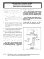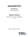
1
AQUASWITCH
AQUASWITCH &
760-A AQUASWITCH
Operation Manual
INSTALLATION • OPERATION • MAINTENANCE
22 August 05
ACCURACY • RELIABILITY • SIMPLICITY
Water Quality Instrumentation
Accuracy • Reliability • Simplicity
TABLE OF CONTENTS
SECTION
PAGE
1
INTRODUCTION
1.1 SCOPE ................................................................................................................................. 1
1.1.1 Functional Descriptions ............................................................................................ 1
1.1.2 Applications .................................................................................................. 1
1.2 SPECIFICATIONS ................................................................................................................ 1
1.2.1 Aquaswitch ............................................................................................................... 1
1.2.2 760-A Aquaswitch ..................................................................................................... 1
1.2.3 HP Solenoid Pilot Valves .......................................................................................... 2
1.2.4 Resistivity Cell .......................................................................................................... 2
1.3 HOW TO ORDER ................................................................................................................. 2
2
INSTALLATION
2.1 GENERAL ............................................................................................................................. 3
2.2 MECHANICAL INSTALLATION............................................................................................. 3
2.2.1 Surface Mounting ..................................................................................................... 4
2.2.2 Panel Mounting Installation ...................................................................................... 4
2.2.3 HP Solenoid Pilot Valve Installation ......................................................................... 4
2.2.4 Cell Installation ........................................................................................................ 4
2.3 ELECTRICAL INSTALLATION ............................................................................................. 5
2.3.1 Aquaswitch Main AC Power ..................................................................................... 5
2.3.2 760-A Aquaswitch Main AC Power .......................................................................... 5
2.3.3 220 VAC Conversion ............................................................................................... 6
2.3.4 Pilot Valve Solenoid Connections (Also see pg. 13) ................................................ 6
2.3.4.1 Optional Solenoid Power .......................................................................... 6
2.3.5 Cell Connections ...................................................................................................... 6
2.3.6 Alarm Relay ............................................................................................................. 7
3
OPERATING PROCEDURES
3.1 GENERAL ............................................................................................................................ 8
3.2 SWITCH AND INDICATOR CONTROLS .............................................................................. 8
3.3 OPERATIONAL CHECK-OUT PROCEDURES ................................................................... 9
3.3.1 760-A Aquaswitch .................................................................................................... 9
3.3.2 Aquaswitch .............................................................................................................. 9
4
COMPONENT IDENTIFICATION, CALIBRATION AND PREVENTIVE CARE
4.1 GENERAL ........................................................................................................................... 10
4.2 PRIMARY COMPONENT IDENTIFICATION ..................................................................... 10
4.3 “PURGE CYCLE” CALIBRATION PROCEDURES ............................................................ 11
4.4 “ALARM RESET” JUMPER ADJUSTMENT ....................................................................... 12
4.5 760-A AQUASWITCH CALIBRATION PROCEDURES ..................................................... 12
4.5.1 Meter Mechanical Zero Reading ............................................................................ 12
4.5.2 Internal Set Point Adjustment ................................................................................. 12
4.5.3 Full Scale Calibration Procedures .......................................................................... 13
4.6 PREVENTIVE CARE ......................................................................................................... 13
5
APPENDIX
A
REPLACEABLE COMPONENTS CHART .......................................................................... 14
B
WARRANTY........................................................................................................................ 14
SECTION 1
Introduction
1.1 SCOPE
This manual provides the necessary information to install,
operate and maintain the Myron L Company’s Aquaswitch/760A Aquaswitch. Sections 1 through 3 provide the user with an
applicational description, mounting, wiring and operational
procedures. Section 4 identifies their primary components and
provides the user with easy-to-use calibration and preventive care
procedures.
Section 5 (Appendix A) provides an easily understood Replaceable
Components Chart.
1.1.1 FUNCTIONAL DESCRIPTIONS
5 Power Plants
6 Laboratories
1.2 SPECIFICATIONS
1.2.1 AQUASWITCH
INPUT POWER:
115 VAC ±15%
220 VAC ±15% (user changeable to 220 VAC)
OUTPUT POWER:
24 VAC (Standard if ordered with Myron L valves)
115 VAC (Standard if ordered without Myron L valves)
220 VAC (Optional)
Both instruments have drip/weather-proof housings which can be
panel or surface mounted. The Aquaswitch is packaged within
a compact 6.0" x 4.8" (152mm x 122mm) housing. The 760-A
Aquaswitch is packaged within a 6.0" x 10.8" (152mm x 274mm)
housing. The standard Aquaswitch does not monitor water quality
itself, but should be used with any reliable resistivity controller
such as the Myron L Company’s 750/760 Series Resistivity
Controllers.
MAXIMUM LOAD PER VALVE OUTPUT:
200 milliamps;
( 5 watts for a 24 V valve)
(25 watts for a 115 V valve)
(50 watts for a 220 V valve)
NOTE:
The 760-A Aquaswitch is an integrated unit requiring no other
Controller.
HOUSING CONSTRUCTION:
Fully gasketed heavy-duty ABS for corrosion resistance.
Rated NEMA type 3.
AQUASWITCH
DIMENSIONS:
Aquaswitch:
6" (152mm) H x 4.8" (122mm) W x 3.8" (97mm) D
760-A Aquaswitch:
6" (152mm) H x 10.8" (274mm) W x 3.9" (99mm) D
Provides automatic switching from exhausted to fresh Dl banks;
push-button override for immediate bank change-over; adjustable
purge timer for “FAILSAFE” operation; front panel LED displays
provide continual status of both Dl banks; and an alarm is
automatically activated as each bank is depleted.
760-A AQUASWITCH
The 760-A Aquaswitch combines the operating features of the
standard Aquaswitch with the additional features of a resistivity
Controller. These include: a linear display meter and a front panel
accessible “SET POINT CHECK” switch. (Set point setting is
internal to discourage unauthorized adjustments).
NOTE:
All specifications for the 760-A Aquaswitch also apply to resistivity
Controller models 760-A2, and 760-A3 unless otherwise
indicated.
1.1.2 APPLICATIONS
1
2
3
4
Deionization (Dl) ultra-pure water treatment systems
Electronics
Food Processing
Plating
AMBIENT TEMPERATURE RANGE:
-22°F (-30°C) to 140°F (60°C)
SHIPPING WEIGHT:
Aquaswitch:
3 Ibs. (1.36 kg.)
760-A Aquaswitch: 5 Ibs. (2.27 kg.)
ALARM RELAY CONTACT RATING:
SPDT 10 amp @ 250 VAC (Non-Inductive), 30 VDC
1.2.2 760-A AQUASWITCH
RANGE:
0-20 megohm-cm
0-2 megohm-cm (Model 760-A2)
0-200 kilohm-cm (Model 760-A3)
READOUT:
4 1/2" (114mm) Analog
ACCURACY:
±2% of span
CELL INPUT:
1 CS10 Series cell required
RELAY FUNCTION:
Single set point control
Continuously adjustable 0-100% of span
SPDT 10 amp @ 250 VAC (Non-lnductive), 30 VDC
1
1.2.3 HP SOLENOID PILOT VALVES
CS10 CELL SPECIFICATIONS
DESCRIPTION: Being corrosive, ultra-pure water can be difficult to
control. Myron L HP valves solve this problem by utilizing tap water
or air to open and close the diaphragm. HP valves, therefore, are
ideal for use with the Aquaswitch and many other water corrosive
solution applications.
CONSTANT:
0.05
SPECIFICATIONS
PRESSURE/TEMPERATURE LIMITS:
100 psi (690 kPa) / 212°F (100°C)
SIZES:
1", 2", or 3" IPS; compatible with plastic or metal piping.
POWER:
24 VAC (2 watts)
MATERIALS:
Body:
Diaphragm:
O Ring:
Exterior Metal:
Dupont ZYTEL (33% glass reinforced NYLON)
NYLON reinforced BUNA N synthetic rubber
DELRIN
18-8 stainless steel (1"); brass (2" and 3")
OPERATING PRESSURE:
N.O.: 3-90 psi (21-620 kPa)
N.C.: 3-150 psi (21-1034 kPa)
PRESSURE LOSS: (See chart below)
WATER TEMPERATURE:
40°F (4°C) to 185°F (85°C)
SOLENOID PILOT PRESSURE:
Water: Min. - equal to Dl water line pressure
Max. N.O. - 90 psi/max. N.C. - 150 psi
Air:
Min. - 2X Dl water line pressure Max N.O. - 90m psi
Max. N.C. - 150 psi
1.2.4 RESISTIVITY CELL
DESCRIPTION: The 760-A Aquaswitch uses a CS10 Cell.
These reliable sensors feature two integral thermistors to ensure
accurate and rapid automatic temperature compensation. The
sturdy polypropylene bushing is modular for easy, inexpensive
replacement. Several alternatives for the metal portion of the cell
are available, depending on the demands of the application.
2
TEMPERATURE COMPENSATION:
Two integral thermistors provide automatic TC to 25°C over
the range of 0-100°C (32-212°F)
BUSHING:
Modular Polypropylene threaded .75" NPT
CABLE:
Shielded; 10'(3 meters) standard; Prespecified lengths up to
100' (30 meters) also available.
DIMENSIONS:
Metal portion 3.75" (95mm)L; 0.5" (13mm) DIA
1.3 HOW TO ORDER
1.
2.
3.
4.
Choose either the Aquaswitch or 760-A Aquaswitch
If 760-A Aquaswitch, also select a resistivity cell:
CS10-S (316 stainless steel)
CS10-T (titanium)
CS10-M (Monel*)
Valves (three or four are required):
024-1HP (1 “ 24v)
024-2HP (2" 24v)
024-3HP (3" 24v)
24V power is required for use with 24V valves such as 024HP series. A 115V to 24V step-down transformer accessory
is available. Order Model VR.
Example of a complete system: 760-A Aquaswitch with CS10-S
cell, VR transformer and 4 Model 024-1HP valves.
*TM Huntington Alloy, Inc.
SECTION 2
Installation
2.1 GENERAL
2.2 MECHANICAL INSTALLATION
Section 2.2 provides the user with the recommended procedures
for mounting the Aquaswitch/760-A Aquaswitch and for completing
their necessary electrical installation.
All Aquaswitch and 760-A Aquaswitch electronics are packaged
inside drip/weather-proof housings. Their physical dimensions have
been designed to allow for both surface and panel mounting.
NOTE:
The Myron L Company recommends that all mounting and electrical
installation procedures be performed by trained and authorized
personnel ONLY! Failure to do so could result in damage to
equipment and/or property
There are three basic guidelines to consider when selecting the
Aquaswitch’s mounting location:
1
Select a site that limits the Aquaswitch’s exposure to
excessive moisture and corrosive fumes.
2
For best results, position your control area as close as
possible to the point(s) being controlled
3
NOTE:
The 760-A Aquaswitch is not designed to operate with a Cell cable
length that exceeds 100' (30 meters).
3
If at all possible, mount the Controller at eye level for
viewing convenience.
2.2.1 SURFACE MOUNTING
NOTE:
Surface mounting will require two (2) user supplied 1/4” 20
mounting screws See, Fig. 2-1 for hole drilling locations. For ease
of surface mounting, a surface mounting plate is available.
Order Part No.: SMP50 for Aquaswitch
SMP60 for 760-A Aquaswitch
STEP 1 Select your site location. Mark and drill the two (2) required
mounting holes.
STEP 2 lace the mounting threads in alignment with the surface
mounting holes.
STEP 3 Insert and securely fasten the two (2)1/4':20 mounting
screws.
2.2.2 PANEL MOUNTING INSTALLATION
A panel mounting fastening kit is provided with all Aquaswitch/
760-A Aquaswitch enclosures. Panel mounting will require the use
of the fastening kit’s two (2) 4-40 mounting screws/nuts or two
(2) #4 x 1/2 “ sheet metal screws. See Fig. 2-1 for panel cutout
dimensions.
STEP 1 Select your site location, mark the appropriate pane I cut
out and complete the necessary panel cut.
STEP 2 Carefully unfasten and separate the front panel from its
enclosure.
STEP 3 Disconnect all panel cable(s)/wires from the enclosure’s
component board(s).
STEP 4 Slide the enclosure through the panel cutout until its flange
contacts the panel.
STEP 5 Insert mounting screws through the flange mounting holes
and tightly secure.
STEP 6 Reconnect all panel cable(s)/wires. (See Fig. 4-1)
2.2.3 HP SOLENOID PILOT VALVE INSTALLATION
STEP 1 Insert the pilot valve unit so that the systems’ INFLOW
source and OUTFLOW process piping connecting ends
are inserted into the valve as shown in Fig. 2-2.
STEP 2 Repeat STEP 1 until all appropriate pilot valve units have
been installed.
NOTE:
The number of pilot valves used will be based upon the user’s
desired application.
4
2.2.4 CELL INSTALLATION (MODEL 760-A ONLY)
NOTE:
Fig. 2-3 illustrates how to properly assemble and install the CS10
Cell assembly into a “T” type mounting fixture. Improper assembly
could result in damage to equipment and/or property.
A CS10 Cell’s mounting orientation must provide a continuous
and adequate circulation flow to prevent the trapping of air bubbles
within the Cell’s electrode area. Failure to do so will result in
conditions that will prevent the cell from functioning properly.
STEP 1 Verify that the Cell components are properly
assembled.
STEP 2 Insert the Cell assembly into the “T” mounting fixture as
shown in Fig. 2-3 and tightly secure.
2.3 ELECTRICAL INSTALLATION
The Aquaswitch and 760-A Aquaswitch require the user to follow
separate electrical installation procedures. In addition, based on
the user’s solenoid voltage specifications, the user will be required
to connect optional Solenoid Power.
NOTE:
All cable watertight restraints are user supplied
2.3.1 AQUASWITCH MAIN AC POWER NOTE:
The following procedures are to be used to install the Aquaswitch
115 VAC main power source. For the procedures to install the
optional 220 VAC main power source, the user must first complete
the installation procedures in Section 2.3.3. Failure to do so could
result in damage to equipment, and/or property.
STEP 1 Verify that the facility’s 115 VAC power source is turned
OFF or disconnected.
STEP 2 Following STEPS 2 and 3 in Section 2.2.2, remove the
front panel.
STEP 3 Place the AC power cord and watertight cable restraint
into the enclosure’s appropriate access hole.
STEP 4 Neatly connect cable wires to the 760-A Control board
TB1 terminal block connectors as shown in Fig. 2-5.
5
2.3.2 760-A AQUASWITCH MAIN AC POWER
NOTE:
The following procedures are to be used to install the 760-A
Aquaswitch 115 VAC main power source. For the procedures
to install the optional 220 VAC main power source, the user
must first complete the installation procedures in Section 2.3.3.
Failure to do so could result in damage to equipment and/or
property.
STEP 1 Verify that the facility’s 115 VAC power source is turned
OFF or disconnected.
STEP 2 Following STEPS 2 and 3 in Section 2.2.2, remove the
front panel.
STEP 3 Place the facility’s AC power cord and watertight cable
restraint into the enclosure’s appropriate access hole.
STEP 4 Neatly connect cable wires to the 760-A Control board
TB1 terminal block connectors as shown in Fig. 2-6.
760-A AQUASWITCH
2.3.3 220 VAC CONVERSION
STEP 1 Verify that the facility’s 115 VAC power source is turned
OFF or disconnected.
AQUASWITCH
STEP 2 Locate and remove 760-A Control board jumpers E1
and E3. (See Fig. 4-1)
STEP 1 Verify that the facility’s 115 VAC power source is turned
OFF or disconnected.
STEP 3 Using one of the removed jumpers, insert it into jumper
E2’s connection holes as shown in Fig. 2-8.
STEP 2 Locate and remove Power Module jumpers E1 and E2.
(See Fig. 4-1)
STEP 4 Follow STEPS 2 and 3 in Section 2.3.3 to convert the
Power Module 115/220 VAC jumpers.
STEP 3 Using one of the removed jumpers, insert it into jumper
E3’s connection holes as shown in Fig. 2-7.
6
2.3.4 PILOT VALVE SOLENOID CONNECTIONS
2.3.5 CELL CONNECTIONS (MODEL 760-A ONLY)
NOTE:
Section 2.3.4 provides the procedures for installing 115 VAC
solenoid valves with maximum load rates of 25 watts per valve.
For the procedures to install solenoid valves other than 115
VAC, see Section 2.3.4.1. (Refer to Fig. 2-10 for recommended
valve wiring.)
STEP 1 Place the CS10 Cell’s interface cable and watertight
cable restraint into the enclosure’s appropriate access
hole.
STEP 1 Place the Bank A solenoid interface cable and
watertight cable restraint into the enclosure’s
appropriate access hole.
2.3.6 ALARM RELAY INSTALLATION
STEP 2 Neatly connect the cable wires to Power Module
terminal block TB2 as shown in Fig. 2-5.
STEP 3 Repeat Steps 1 and 2 to install the Bank B solenoid
interface cable.
STEP 4 Repeat Steps 1 and 2 to install the Bleed Valve
solenoid interface cable.
STEP 2 Neatly connect the cable wires to the 760-A Control
board terminal block TB3 as shown in Fig. 2-6
STEP 1 Place the user supplied Alarm relay interface cable
and watertight cable restraint into the enclosure’s
appropriate access hole.
STEP 2 Neatly connect cable wires to the Power Module TB3
terminal connectors as shown in Fig. 2-5.
NOTE:
See Section 4.4 for the “ALARM RESET” jumper adjustments.
STEP 5 (Optional) Repeat Steps 1 and 2 to install the Process
valve solenoid interface cable.
2.3.4.1 OPTIONAL SOLENOID POWER
CAUTION!
Prior to connecting any solenoid valves other than 115 VAC, it is
essential that the user remove Power Module jumpers E4 and
E5 as shown in Fig. 2-5 (detail in Fig. 2.9 below). Failure to do
so could result in damage to the equipment and/or property.
STEP 1 Place the optional solenoid power cable and watertight
cable restraint into the enclosure’s appropriate access
hole.
STEP 2 Connect the cable wires to the Power Module terminal
block TB2 as shown in Fig. 2-5.
7
SECTION 3
Operating Procedures
3.1 GENERAL
3.2 SWITCH AND INDICATOR CONTROLS
Section 3.2 provides the operational descriptions for each of
the Aquaswitch/760-A Aquaswitch switch and indicator controls.
Section 3.3 provides the user with recommended checkout
procedures.
AQUASWITCH
BANK A/B “IN USE” Indicators
The amber “IN USE” LED indicator light is ON only when its
respective Bank’s solenoid valve is energized.
NOTE:
The units have been designed so that only one (1) Bank (either A
or B) can be in use at any time.
Water Quality “GOOD” Status Indicators
The green “GOOD” status LED light indicators are ON when
their respective Bank’s water quality is acceptable (ABOVE
Controller Set Point).
Water Quality “POOR” Status Indicators
The red “POOR” status LED light indicators are ON only when
their respective Bank’s water quality is unacceptable (BELOW
Controller Set Point).
“BLEED” Indicator Light
The amber “BLEED” LED indicator light is ON only when the
Aquaswitch is in its Purge Cycle (Bleed/Process Water valve(s)
are activated).
“BANK SWITCH” Push Button
When the “BANK SWITCH” is depressed, the Aquaswitch
automatically switches Banks, i.e. turns OFF the currently
selected Bank and turns ON the alternate Bank.
“ALARM RESET” Push Button.
When the-”ALARM RESET” switch is depressed, the Aquaswitch
will automatically turn OFF the Alarm.
760-A AQUASWITCH
4 1/2" ANALOG METER
The 4 1/2" (114mm) linear analog meter provides a continuous
readout of the water being monitored.
“ABOVE/BELOW” Set Point Indicators
The green LED indicator light is ON only when the resistance of
the water is ABOVE the Controller’s internal Set Point.
The red LED indicator light is ON only when the resistance of
the water is BELOW the Controller’s internal Set Point.
“SET POINT CHECK” Switch
When the “SET POINT CHECK” switch is depressed, the
internal Set Point reading is immediately displayed on the
analog meter.
8
3.3 OPERATIONAL CHECKOUT PROCEDURES
3.1
The following checkout procedures are used to verify that the
Aquaswitch or 760-A Aquaswitch is operating properly.
3.2
NOTE:
To complete the checkout procedure, it is assumed that the system
is fully installed and the Aquaswitch is connected to a reliable
resistivity Controller or a 760-A Aquaswitch is installed. It is also
assumed that two fresh Dl banks are on line with the system and
the Controller is indicating water quality in the desired range.
During this test procedure, it will be necessary to simulate GOOD
and POOR water quality. This is done by setting the Set Point
to BELOW or ABOVE the Controller’s actual water resistance
reading. When the Set Point is set BELOW (counterclockwise),
the monitor will simulate “GOOD” water quality. “POOR” water
quality is simulated by setting the Set Point ABOVE (clockwise)
the actual water quality.
3.3.1 760-A AQUASWITCH (ONLY)
STEP 1 Using the “SET POINT CHECK” switch, verify that the
meter indicates the desired Set Point.
NOTE:
If the meter does not indicate the correct Set Point setting, reference
Section 4.5.2 for the procedures to readjust the 760-A Aquaswitch’s
internal Set Point.
STEP 2 Observe resistance reading of water being monitored.
STEP 3 With front panel removed, depress “SET POINT CHECK”
switch and observe the reading on the analog meter. With
a small screwdriver, adjust the Set Point trimmer (R31)
(See Fig. 4-1) to above the reading observed in STEP 2.
Release the “SET POINT CHECK” switch and observe
that the red “POOR” light is ON.
STEP 4 Depress the “SET POINT CHECK” switch and adjust
screw adjustment (R31) until the Set Point is below the
reading observed in STEP 2. Release the “SET POINT
CHECK” switch and observe that the green “ABOVE”
light is ON. Also note the audible click of the relay as the
lights change.
STEP 5 Readjust the Set Point trimmer (R31) to the desired Set
Point setting and replace front panel. This completes the
760-A Aquaswitch Control board checkout.
3.3.2 AQUASWITCH / 760-A AQUASWITCH
NOTE:
For 760-A Aquaswitch users, the term “Controller” refers to the
760-A Control Board functions.
STEP 1 Turn the Purge Cycle trimmer adjustment screw (R2) fully
clockwise to obtain an approximate one minute cycle.
(See Fig. 4-1)
STEP 2 Adjust Controller “Set Point” to simulate “GOOD” water
quality (for the 760-A Aquaswitch, turn the Set Point
trimmer adjustment screw (R31) counterclockwise (see
Section 4.5.2)) and verify the following sequence of
operation.
STEP 3 Push “BANK SWITCH” several times to verify the following
Controller operations.
3.3
3.4
Verify that the “IN USE” indicator lights switch
ON and OFF between Banks A and B each time
“BANK SWITCH” is pressed.
Verify that both Banks A/B “GOOD” water quality
lights remain ON.
Verify that the “BLEED” light remains OFF.
Leave BANK A ON for next step. (If required,
push the “ALARM RESET” switch to reset
alarm.)
NOTE:
If the Logic Module Alarm Reset jumper has been installed to provide
the user with the optional Manual Bank Switch alarm condition, the
alarm will be activated each time the “BANK SWITCH” is pressed.
Otherwise, the alarm will be activated only when the Purge Cycle
time setting has expired. (Refer to Section 4.4)
STEP 4 Adjust Controller Set Point to simulate “POOR” water
quality. (For the 760-A Aquaswitch, turn Set Point trimmer
adjustment screw (R31) clockwise, and verify the following
sequence of operation.)
4.1
4.2
4.3
4.4
BANK A water quality indicates “POOR.”
Yellow “BLEED” light turns ON and water is
purged from system. (This should continue for
about 1 minute.)
After 1 minute, BANK A will turn OFF and BANK
B will turn ON and indicate “POOR” water
quality.
After approximately 1 minute, BANK B should
turn OFF, the “BLEED” light should turn OFF, the
Bleed valve should close and the alarm should
be activated. The system is now entirely shut
down.
NOTE:
If an external alarm is connected, it will be activated when the
Aquaswitch switches Banks. (Press the “ALARM RESET” switch
to turn OFF alarm.)
If an alarm is not connected, an alarm condition can be monitored
by connecting an ohm meter across Power Module Terminals TB32 and TB3-3. The meter should indicate a CLOSED CIRCUIT in
the alarm condition.
STEP 5 Adjust the Controller Set Point to simulate “GOOD” water
quality. (For the 760-A Aquaswitch, turn Set Point trimmer
adjustment screw (R31) counterclockwise and verify the
following sequence of operation.)
STEP 6 Press the “BANK SWITCH.” The BANK A “IN USE” and
“GOOD” water quality indicator lights should turn ON.
Press the “BANK SWITCH” again and BANK B “IN USE”
and “GOOD” water quality indicator lights should turn
ON.
STEP 7 Complete the following steps to return the Aquaswitch to
its normal operating status.
7.1
7.2
7.3
Using the “BANK SWITCH,” select the desired
Bank “IN USE” status.
Adjust the Controller “Set Point” to the desired
minimum water quality. (Refer to Section
4.5.2)
Set Purge Cycle to the desired time delay. (Refer
to Section 4.3)
9
SECTION 4
Component Identification,
Calibration and Preventive Maintenance
4.1 GENERAL
4.2 PRIMARY COMPONENT IDENTIFICATION
Section 4.2 provides detailed illustrations to assist the user in
identifying the Aquaswitch/760-A Aquaswitch primary components
and cable connector designations.
As identified in Section 3, the Aquaswitch/760-A Aquaswitch switch
and indicator components are mounted directly to the front panel.
Component boards and the 760-A Aquaswitch analog meter are
mounted within its enclosure or to the back of the front panel.
Sections 4.3 and 4.4 provide the user with the Aquaswitch
Purge Cycle calibration procedures and Alarm Reset jumper
adjustment.
Section 4.5 provides the user with the 760-A Aquaswitch Calibration
procedures.
Section 4.6 provides the user with the Myron L Company’s
recommended Preventive Care procedures.
10
NOTE:
When performing Calibration procedures, the user must take
extreme care to contact only the trimmer adjustment screws located
on the Aquaswitch component boards. Failure to do so could result
in damage to equipment and/or property. (See Fig. 4-1)
4.3 “PURGE CYCLE”. CALIBRATION PROCEDURES
NOTE:
The Purge Cycle trimmer adjustment screw (R2) (see Fig. 4-1)
determines the time span that the Bleed and Process solenoid
valves are energized during either a Bank A or B Purge Cycle.
STEP 1 Being careful not to excessively strain the cable(s),
unfasten the enclosure’s front panel.
STEP 2 Turn the Logic Module trimmer adjustment screw (R2) to
the desired Purge Cycle setting. (See Fig. 4-3)
NOTE:
Turning the adjustment screw fully clockwise equals a minimum
Purge Cycle of approximately one (1) minute. Turning the
adjustment screw fully counterclockwise equals a maximum Purge
Cycle of nine (9) to thirteen (13) minutes.
11
4.4 “ALARM RESET” JUMPER ADJUSTMENT
4.5.2 INTERNAL SET POINT ADJUSTMENT
NOTE:
The Aquaswitch/760-A Aquaswitch are shipped with an Alarm
condition that occurs whenever the “IN USE” Banks are switched
automatically.
STEP 1 Being careful not to excessively strain the cable,
unfasten and remove the front panel.
This section provides the user with the procedures for activating
an Alarm condition every time the “BANK SWITCH” is manually
pressed.
NOTE:
The Manual Bank Switch alarm condition is in addition to the
standard Automatic Bank Switch alarm condition.
To activate the Manual Bank Switch alarm condition, the user
must reinstall the Logic Module Alarm Reset jumper as shown in
Fig. 4-4.
STEP 1 Being careful not to excessively strain the cable(s),
unfasten the enclosure’s front panel.
STEP 2 Remove the Logic Module Jumper E2 and reinstall it into
its Jumper E1 position as shown in Fig. 4-4.
4.5 760-A AQUASWITCH CALIBRATION PROCEDURES
All 760-A Aquaswitches are calibrated and tested prior to
shipment.
4.5.1 METER MECHANICAL ZERO READING
STEP 1 Turn OFF the Aquaswitch main AC power and verify that
the meter is indicating a zero (0) reading. If the meter does
not indicate a zero (0) reading, proceed to STEP 2.
STEP 2 Remove the meter’s zero adjustment plug to access the
meter’s Mechanical Zero adjustment screw. (See Fig.
3-2)
STEP 3 Turn screw until meter indicates a zero (0) reading and
then replace the plug.
NOTE:
If it becomes necessary to replace a faulty meter, see Fig. 4-1 for
the meter wire/terminal designations.
12
STEP 2 While depressing the “SET POINT CHECK” switch, turn
the 760-A Control board’s R31 adjustment screw (see
Fig. 4-1) until the desired Set Point value is indicated
on the meter display.
NOTE:
The Controller’s Set Point setting is based upon the user’s
particular water purity specifications.
STEP 3 After successfully completing STEP 2, remount the
front panel and tightly secure both retaining screws.
4.5.3 FULL SCALE CALIBRATION PROCEDURES
NOTE:
Before attempting to calibrate the 760-A Aquaswitch analog meter,
refer to Section 4.5.1.
4.7
ALTERNATIVE VALVING CONFIGURATIONS AND
OPERATION FOR CONTINUOUS PROCESS WATER
STEP 1 Turn OFF main AC power.
NOTE:
The following methods will provide an uninterrupted water supply
to process if a fresh Dl bank is NOT in place when the other Dl
bank exhausts. Refer to Fig. 2 - and 2-5 on page 5.
STEP 2 Being careful no! to excessively strain the cables, unfasten
and remove the front panel.
OPTION 1 Requirements:
Continuous process. No interruptions allowed.
STEP 3 Remove all five (5) wires from the 760-A Control board
terminal TB3. (See Fig. 4-1) .
STEP 4 By following the wiring diagram in Fig. 4-5, connect the
Calibrator Module’s lead wires to the 760-A Control board
TB3 terminal block connectors.
STEP 5 Turn ON the main AC power and verify that the 760A Aquaswitch analog meter is indicating a full scale
reading.
NOTE:
If the meter indicates an accurate reading, proceed to STEP 7. If
the meter does not indicate the appropriate reading, proceed to
STEP 6.
STEP 6 Turn the 760-A Control board’s Calibration trimmer (R8)
adjustment screw (see Fig. 4-1) until the meter displays
a full scale reading.
STEP 7 Remove the Calibrator Module’s lead wires and reconnect
the CS10 Cell cable wires as shown in Fig. 2-6.
4.6 PREVENTIVE CARE
Connections:
“A” output (TB2-5) to “A” valve AND “B” valve.
“B” output not connected.
Bleed not connected.
Omit bleed valve.
Configure “A” valve Normally Closed & “B” valve
Normally Open.
OPTION 2 Requirements:
Continuous process. Holding tank between Dl beds
and process.
Purge ok but no prolonged shutdown.
Connections:
Bleed output (TB2-4) connected to bleed valve.
Bleed configured as Normally Closed.
Other connections same as Option 1.
OPTION 3 Requirements:
Continuous process. Purge required only at system
startup.
Connections:
Same as Option 2.
Add manual valve in line with Bleed Valve.
The Myron L Company- recommends that the following Preventive
Care procedures be observed.
1
Try to prevent exposure to excessive heat and moisture.
2
The Aquaswitch main AC power source must be protected
against excessive voltage “spikes.”
3
Take care not to damage the Aquaswitch during handling.
NOTE:
Daily, weekly or monthly maintenance schedules are based upon
the frequency of use and the severity of the environment and
operating conditions.
STEP 1 Repeat the Aquaswitch Checkout procedures to
verify satisfactory operation and/or isolate possible
troubleshooting symptoms.
STEP 2 Check all cable connections to insure that they are free
of moisture and contamination.
STEP 3 Inspect and replace damaged component boards and
cable assemblies.
13
WARRANTY
All Myron L monitors and cells have a one year warranty. If any monitor or cell
fails to function normally, return the faulty unit to the factory prepaid. If, in the
opinion of the factory, failure was due to materials or workmanship, repair or
replacement will be made without charge. A reasonable service charge will
be made for diagnosis or repairs due to normal wear, abuse or tampering.
Warranty is limited to the repair or replacement of monitor or cell only. The
Myron L Company assumes no other responsibility or liability.
Myron L Company, having a policy of continuous product improvement,
reserves the right to make changes in design, specifications and prices
without notice.
SECTION 5
Appendix
REPLACEABLE COMPONENTS CHART
DESCRIPTION
(MLC PART NO.)
AQUASWITCH / 760-A Series Logic Module
AQUASWITCH / 760-A Series Power Module
AQUASWITCH Panel Cable Assembly
760-A Panel Cable Assembly
60RLM
60RPM
ARCA
60RCA
760-A Control Board
760-A2 Control Board
760-A3 Control Board
760 Control Board Cable Assembly
760-A 4 1/2" Analog Meter
760-A2 4 1/2" Analog Meter
760-A3 4 1/2" Analog Meter
521RM
522RM
523RM
60RCBCA
60AM
60AM2
60AM3
Component Board Fuse(s)
1
/8 Amp AGC 1/8
FUSE
0-5 Through 10 VDC Output Board
IMPORTANCE OF THIS ADDENDUM
510
pH Conductivity Instrumentation
Accuracy • Reliability • Simplicity
2450 Impala Drive
Carlsbad, CA 92010-7226 USA
Tel 760-438-2021
Fax 800-869-7668 / 760-931-9189
www.myronl.com
IMPORTANT! PLEASE READ!
ADDENDUM TO USER’S MANUAL
AQUASWITCH 760A AQUASWITCH
Most Aquaswitch users choose Myron L HP SPECIFIC CHANGES (cont’d)
Series 24 vac valves. For this reason, we have
Page 7, Figure 2-9 shows installed jumpers
modified the circuit boards of the Aquaswitch
E4 and E5 as standard. Also on Page 7, Section
and 760 Aquaswitch, and made the necessary
2.3.4 assumes that jumpers have been installed.
corrections to the User’s Manual. As a result:
These jumpers are no longer needed or provided.
1. All power for solenoid valves, regardless Customer supplied power is the standard.
of voltage (24, 110, 220 vac, etc.) must be
Page 10, Figure 4-1 shows jumpers E4 and E5
connected separately to the Power Module
installed on the Power Module; they are no longer
TB2, terminals 1 and 2. Line power to the
needed or provided.
Aquaswitch is no longer used to power the
valves.
On Page 11, Figure 4-2 shows power supplied
to Power Module TB2, Terminals 1 and 2 as an
2. Disregard all Manual references to jumpers
“option.” This is now the standard procedure
E4 and E5. These are no longer installed
at the factory, and they will not be found on
the circuit board of your Aquaswitch or 760
Aquaswitch.
3.
Your User’s Manual and the changes detailed
on this page should be closely followed.
SPECIFIC CHANGES TO USER’S MANUAL
Page 5 of the User’s Manual, Figure 2-5 shows
jumpers E4 and E5 installed. Please note, they are
NOT installed. Figure 2-5 also shows “Optional
Solenoid Input Power” applied to TB2, Terminals
1 and 2. This is now the only method of powering
the valves.
2-5
See Fig. 2-5A at right, which replaces Fig.
Also on page 5, Section 2.3 mentions “optional”
Solenoid Power, depending on solenoid voltage.
All solenoid power, regardless of voltage, must
now be connected to Power Module TB2.
NOTE:
This Addendum applies to all Aquaswitch models shipped from the factory after Oct. 4,
1987 (with the last 4 serial number digits greater than 7023).
MYRON L COMPANY
2450 Impala Drive
Carlsbad, CA 92010-7226
USA
Tel: 760-438-2021
Fax: 760-931-9189
www.myronl.com
Made in USA
ACCURACY • RELIABILITY • SIMPLICITY
Water Quality Instrumentation
Accuracy • Reliability • Simplicity