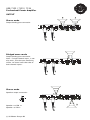
1
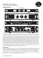
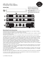
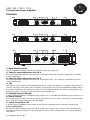
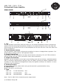
C H 1 LE VE L
POWER
STEREO
M IN
MO N O
PROTECT
OFF
MA X
C H 1 LE VE L
C H 1 LE V E L
M IN
2 C H A N N E L S /5 0 0 W A T T S P R O F E S S I O N A L A M P L I F I E R
PROTECT
M IN
BR ID G E
PO W ER
STE R E O
P R O TE C T
O FF
MA X
USB 7133
2 C H A N N E L S /5 0 0 W A T T S P R O F E S S I O N A L A M P L I F I E R
C H 2 LE V E L
ON
MAX
USB 7132
C H 2 LE VE L
OFF
MA X
MA X
POWER
STEREO
MO N O
M IN
ON
B R ID G E
M IN
C H 2 LE VE L
ON
B R ID G E
M IN
MAX
MO NO
USB 7134
2 C H A N N E L S /1 5 0 0 W A T T S P R O F E S S I O N A L A M P L I F I E R
OWNERS MANUAL
PROFESSIONAL POWER AMPLIFIER
USB 7132
USB 7133
USB 7134
USB 7132 / 7133 / 7134
Professional Power Amplifier
INTRODUCTION
Front Panel
Rear Panel
These series of amplifiers are high performance professional power amplifiers, USB 7132/7133
amplifiers are housed in the same size 1U cases while USB 7134 is in 2U cases. comes with features of light, All amplifiers come with powerful supplies along with massive heat-sinks and cooling
fans. Unique overload protection, output shorted protection and thermal protection systems, ensure
that the amplifier is always operating correctly thereby preventing both the amplifier and your
speakers from failure. We set out to design an amplifier that is as equally at home in live touring
sound environments as it is for installation amplification, We especially wanted to produce amplifiers that are capable of maintaining excellent performance when being driven to their limit with
real loudspeaker loads. Sonic performance is always in the forefront of our minds and to this end
our amplifiers represent the goal of many years work with professional amplifiers. Amplifiers have
impeccable technical specifications, and extensive listening tests by many people with a wide variety of loudspeakers leads us to believe that they Sound pretty.
Unpacking
As part of the quality control, we check every product carefully before packing to ensure that it reaches you in flawless condition.Before you go any further, please check the unit for any physical
damage and retain the shipping carton and all relevant packing materials for use, should the unit
need returning. In the event that damage has occurred, please notify your dealer immediately, so
that a written claim to cover the damages can be initiated.
© US Blaster Europe BV
USB 7132 / 7133 / 7134
Professional Power Amplifier
MOUNTING
Dimension: 482.5mm(19.0 inch)
wide (Including mounting ear),
44mm(1.7 inch)high for USB
7132/7133, 88.8mm(3.5 inch)
high for USB 7134 487.7mm (19.2
inch) deep(for USB
7132/7133/7134 Including protruding adjusting knob & rear hookup).
Mounting & unit dimensions
brackets and rear mounting plates must be fitted. These are available from your dealer. Damage
caused by insufficient support is not covered by the warranty.
To prevent damage to the front panel finish, always use protective plastic cups or washers underneath the rack mounting bolts.
Ventilation gaps between units are not required, however care must be taken to ensure that an
unobstructed free flow of clean air is possible from the back of the unit to the front. It is important
that neither the rear air intakes or front exhaust grilles are covered. The internal airflow of all PA
series amplifiers is designed to minimize contamination of the electronics by the cooling air so fan
filters will not normally be required. If however, the amplifier is to be used in an environment
where the intake air might be excessively dirty, optional external fan filters should be purchased
from your dealer. Fan filters should NOT be fitted unless there is likely to be a problem as they
require regular cleaning to stop them getting clogged. Clogged fan filters will result in the amplifier
going into premature temperature protect.
PLEASE NOTE: Users must ensure that glycol based smoke and related substances are not allowed
to enter the amplifier. Glycol based smoke is HIGHLY corrosive and prolonged exposure will cause
irreparable damage to your amplifier.
Do not expose the amplifier to rain or moisture during either operation or storage. If the unit does
come into contact with moisture, remove the AC power cord immediately and leave it in a suitably
dry, warm place to dry out.
Be aware that when any equipment is taken from a cold location into a hot humid one, condensation may occur inside. Always allow time for the equipment to attain the same temperature as its
environment before applying the AC power cord.
© US Blaster Europe BV
USB 7132 / 7133 / 7134
Professional Power Amplifier
WARNING!
THIS APPLIANCE MUST BE GROUNDED.
The amplifier must always be connected to a 3-wire grounded AC outlet. The rack framework must
also be connected to the same grounding circuit. The unit must NOT be operated unless the power
cables' ground wire is properly terminated - this is important for personal safety as well as for proper control over the system grounding.
IMPORTANT!
The US Blaster amplifiers are designed to use 50Hz AC power. Acceptable AC input supply Voltage
ranges from 200V to 250V
The application of voltages above those specified may cause permanent damage that is not covered
by your warranty. Lower voltages may cause erratic operation.
Note that although the amplifier will operate correctly down to the voltages indicated, the quoted
output power will only be achieved with the stated nominal voltages.
IMPORTANT!
The AC power fuse carried on the rear of the unit must be fitted with the correct type and rating of
fuse.
In the unlikely event of the AC fuse failing without good reason, disconnect the unit from the
power Supply, and always replace with the appropriately rated fuse for continued protection
against damage and fire.
© US Blaster Europe BV
USB 7132 / 7133 / 7134
Professional Power Amplifier
FEATURES
1. Rack Mounting Ears
Two front-panel mounting holes are provided on each mounting ear.
2. Channel Level Attenuator for CH 1
The input attenuator adjusts level for CH 1. In bridged mono the channel 1 attenuator , controls
overall signal level.
3. Channel Level Attenuator for CH 2
The input attenuator adjusts level for CH 2. In bridged mono , the channel 1 attenuator controls
overall signal level.
4. Clip
This light is in fact rather more sophisticated than a simple clip indicator; it actually measures distortion. This may occur either due to clipping, trying to drive too low an impedance speaker load or
any other mechanism that causes the output of the amplifier channel to not be as expected by the
monitoring circuit. The green light turning to red indicates clip.
5. Bridged Stereo Indicator
A green LED lite indicates a bridged stereo mode is on. A red LED lite indicates a mono mode is on.
6. Power Switch
This switch turns the amp on and off. If the amp doesn't turn on when the switch is in the ON position, check the circuit breaker on the rear panel.
7. Power Protection LED
A green LED lite indicates power is ON. A red LED lite indicates power protection mode is ON.
8. Fan Outlet Grill
PA 200/300/500 amplifiers are cooled by a single rear-mounted fan. Cool air flows over the heat
sink and exhausts through the f ont grill. Make sure thi outlet remains clear to r s allow unrestricted airflow.
© US Blaster Europe BV
USB 7132 / 7133 / 7134
Professional Power Amplifier
REAR PANEL
1. Fan
The fan operates continuously while the amp is on. An internal temperature sensor increases the
speed of the fan during high temperature conditions. Air enters through the rear of the amp and
exits through the front grill. Be sure to allow adequate air flow from the rear of the rack where the
amp is mounted on.
2. Mode Selector Switch
The two-position mode switch configures the amplifier for. Stereo or Bridged Mono operation. The
default factory setting is Stereo. See operation modes .
3. Input Connections
Input signals can be connected to the amp via the Phoenix connectors, The 1/4" TRS connectors
and the Female XLR (pin 2 hot) connectors. Power. See Connections .
4. Output Connections
Speakers can be connected via the high current binding posts and the industry -standard Speakon
(NL-4) connectors. Binding posts: One pair (Red- hot, Black- ground) per channel. Speakons: One
connector for each channel. In Bridged Mono mode, the Speakon connector for Channel 1 is used
exclusively. See Connections.
5. Ground Termina
For your safety purpose, please make sure ground terminal is grounded before using.
6. Power Cord
Build-in AC power cord with plug.
7. Fuse
USB 7132
T3.15A-230V/50Hz
Fuse
USB 7133
T4A-230V/50Hz
Fuse
USB 7134
T8A-230V/50Hz
Built-in fuse
Note : fuse for USB 7134 is located at power supply board.
© US Blaster Europe BV
USB 7132 / 7133 / 7134
Professional Power Amplifier
OPERATION MODES
Choosing the appropriate mode
Special consideration when using Bridged mode
Stereo
Bridged
Mode Selection
The two -position Mode Select switch (located on the rear panel) configures the amplifier for Stereo
or Bridged mode. Amplifiers are factory-configured for Stereo mode. Shut the amp off before changing modes.
Stereo
In Stereo mode, each channel operate independently, with their input attenuator controlling their
respective levels. Signal at Channel 1's input produces output at Channel 1's output, while signal at
Channel 2's input produces output at Channel 2's output. Recommended minimum nominal load
impedance for stereo operation is 2 Ohms per channel.
Bridged
Bridged mode straps both amplifier channels together to make a single channel monaural amplifier.
One channel pushes and the other pulls equally, increasing the power output over that of either
channel alone (see Specifications). Channel 1 s attenuator is used to control signal level.
Use extreme caution when operating the amplifier in Bridged mode .Never ground either side of the
speaker cable when the amplifier is in Bridged mode; both sides are hot.
If an output patch panel is used, all connections must be isolated from each other and from the
panel .The recommended minimum nominal load impedance in the Bridged mode is 4 ohms, which
is the equivalent to driving both channels separately at 2 ohms.
When the amplifier channel is operated in Bridge mode, the power available doubles allowing larger
speakers to be driven. Two things must be kept in mind when bridge mode is used, namely the
minimum impedance that can be driven up to 4 ohms and if binding post outputs are used, the
speaker wiring must be changed according to this manual. See connections.
© US Blaster Europe BV
USB 7132 / 7133 / 7134
Professional Power Amplifier
CONNECTIONS
Female XLR
1. Ground
2. Negative
3. Positive
Female XLR
Very high current is available at
the outputs.
Tip - positive
Ring - negative
Sleeve - Ground
Please connect your output
cable to the + and - terminals
of each section precisely as
shown.
Outputs
Speakers are connected using the high-current rive-way binding posts or speakon connectors, or
both.
Stereo / Parallel
Speaker+ to PIN 1+ or PIN 2+
Speaker- to PIN 1- or PIN 2See operation modes.
© US Blaster Europe BV
USB 7132 / 7133 / 7134
Professional Power Amplifier
INPUTS
For each channel, there is a 1/4 phone jack socket and female XLR socket provided for signal input
on the rear panel of the amplifier. Each is electronically balanced at an impedance greater than 20k
ohms.
The phone jacks and XLR connectors are internally wired in parallel, and therefore either socket
may be used for the input signal.
The HOT, +, or in phase connection is to pin 2 of the XLRs and the TIP of the phone jacks.
The COLD, -, or out of phase connection is to pin 3 of the XLRs and the phone jack RING.
Pin 1 of the XLR s and the phone jack SLEEVE are internally connected to the chassis. The screen
of the input cable should always be connected to one of these points to ensure that EMC regulations are met. The cable shield ground should also be connected to the equipment which is providing
the input signal.
Unbalanced operation
When feeding the PA series amplifiers from unbalanced sources, connect the signal conductor to pin
2 of the XLR or the phone jack TIP, with the cable screen going to pins 1 and 3 of the XLRs or the
SLEEVE and RING (If avaialable) of the phone jack.
For bridge mode operation, signal can be provided from either channel 1 or channel 2, or both, but
no matter how to input the signal ,the output level is only controlled by channel 1 attenuator.
© US Blaster Europe BV
USB 7132 / 7133 / 7134
Professional Power Amplifier
OUTPUT
Stereo mode
Output binding post connection
Bridged mono mode
Output binding post connection
Note : if single channel input , it can
also work , but the input sensitivity
will be 1.4 times lower than that of
both channel inputs .
Stereo mode
Speakon output connection
Speaker+ to PIN 1+
Speaker- to PIN 1-
© US Blaster Europe BV
USB 7132 / 7133 / 7134
Professional Power Amplifier
SAFETY INFORMATION
1) Read these instructions and keep it in a handy place for future reference.
2) Be sure to follow all instructions and heed all warnings
3) Clean only with a dry cloth.
4) Do not block any ventilation openings. Install in accordance with the manufacturer's instructions.
5) Do not install near any heat sources such as radiators, heat registers, stoves, or other apparatus
that produce heat.
6) Do not defeat the safety purpose of the polarized or grounding-type plug. A polarized plug has
two blades with one wider than the other. A grounding-type plug has two blades and a third grounding prong. The wide blade or the third prong is provided for your safety. If the provided plug does
not fit into your outlet, consult an electrician for replacement of the obsolete outlet.
7) Protect the power cord from being walked on or pinched, particularly at plugs, convenience
receptacles, and the point where they exit from the apparatus.
8) Only use attachments/accessories specified by the manufacturer.
9) Use only with a cart, stand, bracket, or table specified by the manufacturer, or sold with the
apparatus. When a cart is used, use caution when moving the cart/ apparatus combination to avoid
injury from tip-over.
10) Unplug this apparatus during lightning storms or when unused for long periods of time.
11) Refer all servicing to qualified service personnel. Servicing is required when the apparatus has
been damaged in any way, such as power-supply cord or plug is damaged, liquid has been spilled
or objects have fallen into the apparatus, the apparatus has been exposed to rain or moisture, does
not operate normally, or has been dropped.
DO NOT REMOVE COVERS. NO USER SERVICEABLE PARTS INSIDE.
REFER SERVICING TO QUALIFIED SERVICE PERSONNEL.
THIS EQUIPMENT MUST BE GROUNDED. SHOULD NOT BE NECESSARY TO
REMOVE ANY PROTECTIVE GROUND OR SIGNAL CABLE SHIELD CONNECTIONS TO PREVENT GROUND LOOPS. ANY SUCH DISCONNECTIONS ARE OUTSIDE THE RECOMMENDED PRACTICE OF GROUND AND WILL RENDER ANY
EMC OR SAFETY CERTIFICATION VOID.
For continued compliance with international EMC legislation ensure thatall input
cables are wired with the cable screen connected to Pin 1 of the XLR connectors
and/or the jack plug sleeve.
WARNING! This equipment can create high sound levels. Exposure without
adequate protection could cause permanent damage to hearing.
© US Blaster Europe BV
USB 7132 / 7133 / 7134
Professional Power Amplifier
CALCULATING IMPEDANCE
Measured in ohms, impedance is a measure of AC resistance. Loudspeakers generally come in 16, 8
or 4 ohm varieties. Amplifiers have a low limit to what impedance they can drive without being
overloaded, there is not usually an upper limit. The PA series can drive any impedance between an
open circuit and no less than 2 ohms when in stereo and between an open circuit and no less than
4 ohms when bridged.
If the speakers are wired in series, just add their impedances together. If they are in parallel there is
a simple rule: two impedances the same will equal half the individual impedance, for example 8 & 8
= 4 or to take this further, four 8 ohm drivers = 2 ohms (16 & 16= 8 / 8 & 8 = 4 / 4 & 4 = 2).
Table for specification
ITEMS
CONDITIONS
USB 7132
USB 7133
USB 7134
8 Ohms 0.1%
THD 1KHz
200W RMS
x 2 Channel
300W RMS
x 2 Channel
450W RMS
x 2 Channel
4 Ohms 0.1%
THD 1KHz
300W RMS
x 2 Channel
400W RMS
x 2 Channel
700W RMS
x 2 Channel
2 Ohms 0.1%
THD 1KHz
400W RMS
x 2 Channel
500W RMS
x 2 Channel
900W RMS
x 2 Channel
Bridged Mono
8 Ohms 0.1%
THD 1KHz
600W RMS
850W RMS
1400W RMS
Bridged Mono
4 Ohms 0.1%
THD 1KHz
800W RMS
1000W RMS
1800W RMS
Power 1W
4 Ohms 1KHz
0.2%
0.25%
0.3%
Rated power
4 Ohms 1KHz
0.03%
0.055%
0.06%
INPUT
SENSITIVITY
Output rated power
(Level at Max.)
775 ±30mV
950 ±30mV
1400 ±30mV
VOLTAGE GAIN
Output rated power
31dB
31dB
31dB
S/N RATIO
Rated power 1 KHz
+A (Level at Mid)
0.2%
0.25%
0.3%
FREQUENCY
RESPONSE
1 KHz=0dB/-0.5dB
(Level at Max.)
10--30K
10--30K
10--30K
CH. SEPERATION
Rated power
4 Ohms 1KHz
67 dB
70 dB
65.5 dB
OUTPUT
POWER
DISTORSION
© US Blaster Europe BV
USB 7132 / 7133 / 7134
Professional Power Amplifier
USER RESPONSIBILITY
Your PA600/800/1400 series amplifier is very powerful and can be potentially dangerous to loudspeakers and operators alike. It is your responsibility to read important precautions and make sure
that the amplifier is installed, wired, and operated properly as instructed in this manual.
Many loudspeakers can be easily damaged or destroyed by overpowering, especially with the high
power available from a bridged amplifier. Always be aware of the speaker s continuous and peak
power capabilities. We are is not responsible for damage to loudspeakers for any reason.
Speaker protection
All loudspeakers have electrical, thermal and physical limits which must be observed to prevent
damage or failure. Cone or compression drivers can be damaged (sometimes to the point of failure)
by excessive power, low frequencies applied to high frequency drivers, severely clipped wave forms,
and DC voltage. All Series amplifiers automatically protect speakers from DC voltages and subsonic
signals.
Tour Class Protection
The amplifier s clipping point is its maximum peak output power. At maximum peak output power,
PA 600/800/1400 amplifiers will deliver more power than many speakers can safely handle. Be sure
the peak power capability of the amplifier is not excessive for your speaker system. To ensure that
the speakers never receive excessive power, and to prevent amplifier from clipping, use a properly
adjusted external limiter (or a compressor with a ratio of 10:1 or higher) to control power output.
Use one compressor/limiter for each frequency ban d in systems with active electronic crossovers.
© US Blaster Europe BV