1
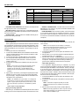
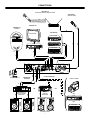
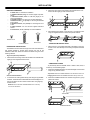
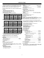
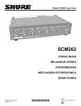
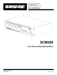
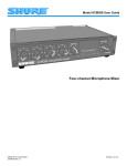
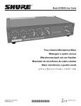
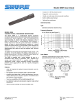
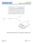
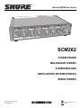
Model SCM262 User Guide SCM262 STEREO MIXER MÉLANGEUR STÉRÉO STEREOMISCHER MEZCLADORA ESTEREOFONICA MIXER STEREO ©2012 Shure Incorporated 27A15638 (Rev. 2) Printed in U.S.A. ! IMPORTANT SAFETY INSTRUCTIONS ! 1. 2. 3. 4. 5. 6. 7. 8. 9. 10. 11. READ these instructions. KEEP these instructions. HEED all warnings. FOLLOW all instructions. DO NOT use this apparatus near water. CLEAN ONLY with dry cloth. DO NOT block any ventilation openings. Install in accordance with the manufacturer's instructions. DO NOT install near any heat sources such as radiators, heat registers, stoves, or other apparatus (including amplifiers) that produce heat. DO NOT defeat the safety purpose of the polarized or grounding-type plug. A polarized plug has two blades with one wider than the other. A grounding type plug has two blades and a third grounding prong. The wider blade or the third prong are provided for your safety. If the provided plug does not fit into your outlet, consult an electrician for replacement of the obsolete outlet. PROTECT the power cord from being walked on or pinched, particularly at plugs, convenience receptacles, and the point where they exit from the apparatus. ONLY USE attachments/accessories specified by the manufacturer. 12. USE only with a cart, stand, tripod, bracket, or table specified by the manufacturer, or sold with the apparatus. When a cart is used, use caution when moving the cart/apparatus combination to avoid injury from tip-over. 13. UNPLUG this apparatus during lightning storms or when unused for long periods of time. REFER all servicing to qualified service personnel. Servicing is required when the apparatus has been damaged in any way, such as power-supply cord or plug is damaged, liquid has been spilled or objects have fallen into the apparatus, the apparatus has been exposed to rain or moisture, does not operate normally, or has been dropped. DO NOT expose the apparatus to dripping and splashing. DO NOT put objects filled with liquids, such as vases, on the apparatus. The MAINS plug or an appliance coupler shall remain readily operable. The airborne noise of the apparatus does not exceed 70dB (A). Apparatus with CLASS I construction shall be connected to a MAINS socket outlet with a protective earthing connection. To reduce the risk of fire or electric shock, do not expose this apparatus to rain or moisture. Do not attempt to modify this product. Doing so could result in personal injury and/or product failure. Operate this product within its specified operating temperature range. 14. 15. 16. 17. 18. 19. 20. 21. This symbol indicates that dangerous voltage constituting a risk of electric shock is present within this unit. This symbol indicates that there are important operating and maintenance instructions in the literature accompanying this unit. WARNING: Voltages in this equipment are hazardous to life. No user-serviceable parts inside. Refer all servicing to qualified service personnel. The safety certifications do not apply when the operating voltage is changed from the factory setting. WARNING: This product contains a chemical known to the State of California to cause cancer and birth defects or other reproductive harm. SHURE SCM262 DESCRIPTION The SCM262 Stereo Mixer is designed for restaurants, classrooms, corporate training, aerobics classes, and other situations where a paging/ public announcement system is combined with background music or other program material. The Shure Model SCM262 is a stereo mixer intended for sound reinforcement applications that integrate microphones with consumer stereo products. It incorporates two active-balanced microphone inputs with three unbalanced stereo aux level inputs. FEATURES • • • • • • Designed to combine paging with background music. One active-balanced, XLR microphone input channel. One active-balanced XLR microphone and 1/4-in. TRS line input channel. Three STEREO INPUT channels Stereo AUX level OUTPUTs Stereo MIC/LINE OUTPUTs • • • • • • • BASS and TREBLE tone controls on the master output. 1/2-rack chassis. 12 V phantom power for condenser microphones. Internal power supply. Removable power cable. Ducking function (defeatable). Jukebox mute function (defeatable). FRONT PANEL 2 1 3 � MIC Channel Gain Controls, 1-2. Control the gain levels of the MIC channels and LINE IN 2 (MIC 2). 4 5 6 � POWER Indicator. Lights up to indicate when the unit is plugged in and receiving power. � STEREO Channel Gain Controls, 1-3. Control the gain levels from CD players, juke boxes, VCRs, or other consumer stereo equipment connected to the STEREO inputs. NOTE: The SCM262 does not have a power switch. To turn the unit off, unplug the power cord or use an external power strip with a switch. However, it can remain plugged in as it uses very little power when idle. � BASS and TREBLE Controls. Control the boost/cut of the low- and high-frequency of the shelving filters. � POWER Switch NOTE: Country dependent � MASTER Gain Control. Allows adjustment of the overall output gain. REAR PANEL 1 2 3 4 5 6 7 � Power Connector. Accepts 100-120 Vac (SCM262) or 220240 Vac (SCM262E). � Left/Right STEREO INPUTS, 1-3. These phono jacks are stereo inputs for connection to consumer stereo devices. � Left/Right MIC/LINE Output Connectors. These 1/4-in. connectors are stereo, balanced outputs for use with professional audio equipment. Controlled by DIP switch. � MIC Channel 2 INPUT. Microphone channel 2 has two available inputs. There is a 1/4-in. connector for balanced/ unbalanced line-level connections, or an XLR connector for balanced mic-level connections. � Left/Right AUX Output Connectors. These phono jacks are stereo, unbalanced outputs for use with consumer stereo equipment. � MIC Channel 1 INPUT. This is an XLR connector for balanced mic-level connections. � DIP Switches. These allow you to adjust the SCM262 for specific applications. See DIP Switches. 5 UP 2 3 4 5 6 7 DIP SWITCH FUNCTION POSITION UP (default) DOWN 1 LEFT OUTPUT MIC/LINE Line Mic 2 RIGHT OUTPUT MIC/LINE Line Mic 3 MIC 1 DUCKING Off On 4 MIC 2 DUCKING Off On 5 DUCKING LEVEL – –20 dB 6 STEREO 3 JUKEBOX MUTE Off On 7 12 V PHANTOM Off On MIC MIC ON ON -20 ON ON 1 OFF OFF LINE LINE OFF OFF -∞ DOWN L OUTPUT R OUTPUT MIC 1 DUCKING MIC 2 DUCKING DUCKING LEVEL (dB) ST. 3 JUKEBOX MUTE 12 V PHANTOM DIP SWITCHES LEFT/RIGHT OUTPUT MIC/LINE: DIP switches 1 and 2 adjust the left and right outputs for line- or mic-level operation. MIC 1/MIC 2 Ducking: When ducking is on, the SCM262 will automatically lower the gain of all STEREO inputs when someone is speaking into one of the microphones. DUCKING LEVEL: Adjusts the amount of STEREO channel gain reduction when ducking is activated. STEREO 3 JUKEBOX MUTE: This DIP switch turns the Juke Box Mute feature on or off. When on, any source connected to STEREO 3 will mute STEREO 1 and 2 inputs. PHANTOM POWER: When in the down position, this switch activates a 12 V phantom power source for condenser microphones. Phantom power does not affect the operation of balanced, dynamic microphones, so one can be connected to the SCM262 in combination with a condenser microphone. APPLICATIONS so the talker can be heard more clearly. Once the talker is finished, the music resumes. General Application This is a general setup for most situations which require the combined use of professional microphones and consumer stereo equipment. Using this general setup, there are several other options available for further adjusting the SCM262 for your sound system. See the diagram on the facing page. 1. Turn all gain controls counterclockwise. 2. Connect L/R STEREO INPUTS of the SCM262 to the L/R stereo outputs of the desired stereo audio equiment (CD players, VCRs, televisions, juke boxes, etc.). 3. Connect microphone(s) to the MIC INPUTS on the SCM262. 4. For microphones which require phantom power, such as condenser microphones, place DIP switch 7 in the down position (phantom power on). 5. Connect the L/R outputs of the SCM262 to the L/R inputs of the amplifier. NOTE: Use a microphone with an ON/OFF or pushbutton switch for the Paging with Ducking Application. A microphone without a switch will false-trigger, causing unwanted interruptions in the program material. 1. Connect the SCM262 to the sound system as described in General Application. 2. Set DIP switch 3 or 4 to the down position to activate ducking for microphone channel 1 or 2, respectively. 3. Set DIP switch 5 position. The Down position sets the ducking so that the program sound is lowered 20 dB when someone uses a microphone. The Up position sets the ducking so that the program sound is muted when someone uses a microphone. Jukebox Mute Application In this application, designed primarily for Jukeboxes, any sound source connected to the STEREO 3 channels will automatically mute any sound coming over the STEREO 1 and 2 channels. This way, a CD player can be playing music, and then when someone plays a song on the Jukebox, the SCM262 will automatically mute the CD player channels and switch to the Jukebox. STEREO 1 and 2 channels will remain muted for about 30 seconds after program material is finished, to allow the jukebox time to move on to the next song. 1. Connect the SCM262 to the sound system as described in General Application. 2. Connect the L/R audio outputs of the jukebox to the L/R inputs of STEREO 3. NOTE: If you are using a consumer stereo amplifier, use the AUX OUTs. If you are using a professional audio power amplifier, use the LINE OUTs. The MIC/LINE and AUX OUTPUTs can be used simultaneously to feed two separate amplifiers. 6. Apply power to the mixer by connecting the supplied power cable between the power connector on the mixer and the appropriate AC power supply. The green POWER LED will illuminate to indicate that the mixer is powered on. *NOTE: The SCM262 has no power switch. It is designed to be plugged into a power strip which supports the whole sound system. A typical power strip will have a power switch, so that when the power strip is powered on, the SCM262 is powered on. NOTE: This feature is designed especially for use with jukeboxes, but will work for any equipment connected to STEREO 3. *Power Switch, country dependent. 3. Set DIP Switch 6 to the down position (Jukebox Mute on). Paging with Ducking Application NOTE: If the ducking application is used in conjunction with the Jukebox Mute application, then activated microphones will mute or duck the STEREO 3 input. With Ducking on, the SCM262 will automatically sense when someone is talking into one of the microphones and lower the volume of the music 6 CONNECTIONS MIC INPUT 2 WIRELESS MICROPHONE SYSTEM MIC INPUT 1 MICROPHONE AUX INPUTS AUX INPUT 3 JUKEBOX AUX INPUTS TELEVISION CD PLAYER OR AM/FM RECEIVER L OR R VCR TAPE DECK R R L L POWER SUPPLY R L/R AUX OUTPUTS L/R MIC/LINE OUTPUTS VIDEO CAMERA L OR PROFESSIONAL AUDIO POWER AMPLIFIER OR CONSUMER STEREO AMPLIFIER R OR L VCR OR TAPE DECK LOUDSPEAKERS LOUDSPEAKERS 7 INTERNAL MODIFICATIONS WARNING! Voltages in this equipment are hazardous to life. No user-serviceable parts inside. Refer all servicing and modifications to qualified service personnel. DISASSEMBLY To remove MIC 2/LINE 2 from the left outputs, remove R910. To remove MIC 2/LINE 2 from the right outputs, remove R911. To access the printed circuit board (pc board) for internal modifications, use the following steps: 1. Unplug the power cord. 2. Remove the knobs and retainer nuts from the front panel. Low-Cut Filter To eliminate the 80 Hz, low-cut filter, remove resistor R501 (mic 1), or resistor R519 (mic 2). Place a 10 to 33 F capacitor in X501 (mic 1) or R502 (mic 2). The polarity of the capacitor does not matter.To change the frequency of the low cut filter, remove resistor R501 (mic 1) or R519 (mic 2), and place the proper capacitor into X501 (mic 1) or X502 (mic 2) to get the desired corner frequency. The following tables list the low-cut frequency corners for some of the most common capacitor values: 3. Remove the two screws at each bottom corner of the front panel. 4. Remove the four screws at each corner of the back panel. 5. Slide the back panel and pc board out from the rear of the chassis. Capacitor Value .033 F .047 F .068 F .1 F .22 F CAUTION: When reassembling the SCM262, DO NOT OVERTIGHTEN the knob retainer nuts. Use a minimal amount of force to secure the nut (0.6-0.8 Nm (5-7 inlb)). Damage to the internal components will result if too much force is used. Corner Frequency 803 Hz 564 Hz 390 Hz 265 Hz 120 Hz Capacitor Value .33 F .47 F .68 F 1.0 F 2.2 F Corner Frequency 80 Hz 56 Hz 39 Hz 26.5 Hz 12 Hz Ducking Depth This modification adjusts the level of ducking depth attenuation of the input channels when ducking is activated. The aux ducking depth may be changed by removing resistor R213 and inserting a resistor into jumper X202. Use the following tables to determine the proper resistor value for the desired ducking depth. Mono Mixer Modification This modification allows all the inputs to be mixed to a single mono signal sent over both the left and right outputs. Short jumper X203. Phantom Power Disable Ducking Depth 6 dB 9 dB 15 dB 20 dB 24 dB 29 dB This modification disables the phantom power per channel. To disable the phantom power from mic 1, remove resistor R121. To disable the phantom power from mic 2, remove resistor R122. 15 dB Mic Preamplifier Pad When a microphone has an extremely high signal, getting the desired gain might be difficult -- a small turn of the gain control might change the sound from a whisper to deafeningly loud. This modification adds a 15 dB Mic preamplifier pad to allow more accurate gain adjustment with extremely high microphone signals. Remove R160 (mic 1) or R183 (mic 2). Resistor Value 4,000 5,000 7,500 10,000 12,000 15,000 Ducking Depth 36 dB 42 dB 47 dB 50 dB 55 dB Resistor Value 20,000 25,000 30,000 33,000 40,000 Ducking Threshold This modification adjusts the threshold for activating the ducking circuit. The ducking threshold can be raised or lowered by first removing resistor R333, and then placing a resistor (R) at jumper X303. To lower the ducking threshold, use a resistor value (R) less than 2k ohms. To raise the ducking threshold, use a resistor value (R) greater then 2k ohms. Hard Panning MIC Channels To remove MIC 1 from the left outputs, remove R912. To remove MIC 1 from the right outputs, remove R913. 8 INSTALLATION SUPPLIED HARDWARE • • • • • • • • 2. Attach the short rackmount brackets to the outsides of the combined units with eight (8) of the bracket screws. 4 rubber feet. For stand-alone installation. 1 rackmount bracket, long. For half-rack (single unit) installations. 1 rackmount bracket, short. For half-rack (single) or dual-mount installations. 2 straddle brackets. For dual-mount or fixed installations. 12 bracket screws, 1/4-in. (6 mm). For securing the brackets to the chassis. 4 rackmount screws, 1 in. (2.5 cm). For mounting the unit in a rack. 4 plastic washers. For use with the supplied rackmount screws. 4 wood screws, 1/2 in. (1.25 cm). For fixed installations 3. After attaching the brackets, mount the unit in an equipment rack using the supplied rackmount screws and plastic washers. Bracket Screw Rackmount Screw Wood Screw STAND-ALONE INSTALLATION RACKMOUNT INSTALLATION 1. Adhere the four (4) supplied rubber feet to the bottom of the unit at each corner. This will keep it from sliding and protect the table surface. The SCM262 can be mounted as a single unit or dual-mounted with either another SCM262 or another Shure half-rack unit such as the SCM268 or DFR11EQ. Attach the rackmount brackets using one of the following methods: Single unit (half-rack) installation: 1. Attach the short and long rackmount brackets to the SCM262 with eight (8) of the supplied bracket screws. FIXED INSTALLATION To permanently affix the SCM262 above or below a table, shelf, or counter top, use the following steps: 1. Fasten the straddle brackets to the recessed edges of the chassis using four (4) bracket screws. Top mount: Fasten the straddle brackets to on the bottom of the unit Hanging mount: Fasten the straddle brackets to the top of the unit. Dual-mounted installation: 2. Fasten the straddle brackets to the surface using the four (4) supplied wood screws. 1. Connect the two units together side-by-side using two (2) straddle brackets. The brackets should straddle the recessed edges on on the top and bottom of each chassis. Fasten them using eight (8) bracket screws. NOTE: Be sure to use both straddle brackets-one on the top and one on the bottom. TOP MOUNT HANGING MOUNT 9 SPECIFICATIONS Measurement Conditions (unless otherwise specified):Tone controls centered; Line voltage 120 Vac, 60 Hz (SCM262) or 230 Vac, 50 Hz (SCM262E); full gain; 1 kHz, one channel activated; source impedances: Mic 150 ; Line/Aux 40 , terminations: Line/Mic/Aux 20 k Ducking Mic channels 1 and 2 Levels .................................... –20 dB or – dB Activation time ............................................................. 10 ms (typical) Mic Deactivation time ........................................................ 2 s (typical) Jukebox Mute Deactivation Time .................................... 30 s (typical) Phantom Power Frequency Response (Ref 1 kHz, channel and master controls centered) 12 Vdc open-circuit through 680 resistors Operating Voltage MIC/LINE Inputs: 150 Hz to 20 kHz 2 dB AUX Inputs: 20 Hz to 20 kHz 2 dB SCM262: 100—120 Vac, 50/60 Hz, 60 mA SCM262E: 220—240 Vac, 50/60 Hz, 30 mA Low-Cut Filter (Microphone inputs only) Temperature Range 3dB down at 80 Hz, 6 dB/octave Operating...............................................–7 to 49 C (20 to 120 F ) Storage .................................................–29 to 74 C (–20 to 165 F) Voltage Gain (typical, controls full clockwise) Overall Dimensions Output Input Mic Line Aux Low-impedance mic (150 ) 32 dB 72 dB 60 dB Line –9 dB 31 dB 19 dB Stereo –5 dB 35 dB 23 dB 43 x 218 x 162 mm (1.72 x 8.60 x 6.37 in.) Net Weight:1.1 kg (2 lbs, 5 oz) Certifications SCM262: UL, cUL listed by Underwriters Laboratories. SCM262E: Conforms to European Union directives, eligible to bear CE marking; Certified to EN 60 065; meets European Union EMC Immunity Requirements (EN 50082-1: 1992, EN 50082-2: 1992) Inputs Conforms to European Regulation (EC) No. 1275/2008, as amended. Impedance Input Designed for use with Actual (typical) The CE Declaration of Conformity can be obtained from Shure Incorporated or any of its European representatives. For contact information please visit www.shure.com Input Clipping Level Mic (XLR) <600 1.4 k –16 dBV Line <10 k 155 k +24 dBV Stereo <2 k 21 k >28 dBV Output Designed for use with Actual (typical) Output Clipping Level The CE Declaration of Conformity can be obtained from: ww.shure.com/europe/compliance Authorized European representative: Shure Europe GmbH Headquarters Europe, Middle East & Africa Department: EMEA Approval Jakob-Dieffenbacher-Str. 12 75031 Eppingen, Germany Phone: 49-7262-92 49 0 Fax: 49-7262-92 49 11 4 Email: [email protected] Outputs Impedance Mic > 600 3 –22 dBV Line >5k 300 +18 dBV Aux 10 k 1.5k +5 dBV Replacement Parts Knob, Master (blue) ............................................... 95B8752 Knob, Channel Gain (white)................................... 95A8752 Line (Power) Cords: SCM262: 100—120 Vac (US/Canada) ............. 95B8762 SCM262E: 220—240 Vac (EU)......................... 95B8778 Fuse: SCM262 (5x20 mm, 250V, 100mA, time delay) ............................................ 80Z730 SCM262E (5x20 mm, 250V, 40mA, time delay) .............................................. 80M258 Hardware Kit .......................................................90AW8100 Link Bars (Bracket) ................................................ 53B8443 Single Mount Bracket............................................. 53A8484 Dual Mount Bracket .............................................. 53E8484 Optional Accessories Line (Power) Cord, 230—240 Vac (UK) ................. 95A8713 Service Statement Total Harmonic Distortion <0.25% at +4 dBu output level, (through 22 Hz—22 kHz filter; MIC Input 1 and Master at center, all other controls full counterclockwise) Equivalent Input Noise (150 source; A-Weighted) –128 dBV Output Noise (channel controls full counterclockwise, A-Weighted) Master full counterclockwise .................................................. –95 dBV Master full clockwise .............................................................. –59 dBV Common Mode Rejection >70 dB at 1 kHz Polarity All inputs to all outputs are non-inverting. Overload and Shorting Protection Shorting outputs, even for prolonged periods, causes no damage. Microphone inputs are not damaged by signals up to +10 dBV; Line and Aux inputs by signals up to +28 dBV For additional service or parts information, please contact Shure's Service department at 1-847-600-8699. Outside the United States, please contact your authorized Shure Service Center. Equalization Bass (Low-frequency shelving, corner frequency at 250 Hz) 6 dB Treble (High-frequency shelving, corner frequency at 4 kHz) 6 dB 10 United States, Canada, Latin America, Caribbean: Shure Incorporated 5800 West Touhy Avenue Niles, IL 60714-4608 USA Phone: 847-600-2000 Fax: 847-600-1212 (USA) Fax: 847-600-6446 Email: [email protected] www.shure.com ©2011 Shure Incorporated Europe, Middle East, Africa: Shure Europe GmbH Jakob-Dieffenbacher-Str. 12, 75031 Eppingen, Germany Phone: 49-7262-92490 Fax: 49-7262-9249114 Email: [email protected] Asia, Pacific: Shure Asia Limited 22/F, 625 King’s Road North Point, Island East Hong Kong Phone: 852-2893-4290 Fax: 852-2893-4055 Email: [email protected]