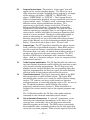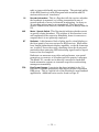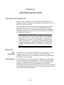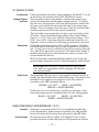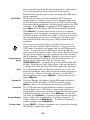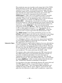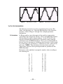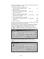
1
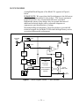
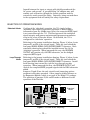
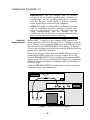
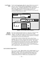
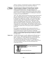
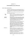
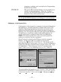
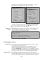
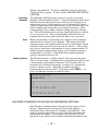
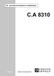
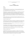
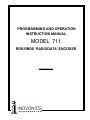
PROGRAMMING AND OPERATION
INSTRUCTION MANUAL
MODEL 711
RDS/RBDS ‘RADIODATA’ ENCODER
__________
—— USER’S RECORD —-Model 711 – Serial No. ____________
Date Purchased __________________
Warranty Card Mailed? — o
PROGRAMMING AND OPERATION
INSTRUCTION MANUAL
MODEL 711
RDS/RBDS ‘RADIODATA’ ENCODER
January, 2001
LICENSE NOTICE
The Inovonics Model 711 RDS/RBDS Encoder is
manufactured under license from the French firm,
Aztec Radiomedia, a division of Digigram Corp.
1305 Fair Avenue • Santa Cruz, CA 95060
TEL: (831) 458-0552 • FAX: (831) 458-0554
Visit our Website: www.inovon.com
TABLE OF CONTENTS
Section I - INTRODUCTION
Model 711 Product Description ...................................................................................... 3
The “Radio Data System”— RDS vs. RBDS—General—
Features
Model 711 Technical Specifications ................................................................................ 4
Block Diagram .................................................................................................................. 5
Section II - THE RADIO DATA SYSTEM
RDS in Europe .................................................................................................................. 6
The RDS System .............................................................................................................. 6
Universal Encoder Communication Protocol ................................................................. 7
RDS Applications Supported by the Model 711 ............................................................. 7
PI—PS—PTY—TP—TA—AF—DI—M/S—RT—FFG
Section III - ENCODER INSTALLATION
Unpacking and Inspection ............................................................................................. 10
Mounting ......................................................................................................................... 10
Rack Requirement—Heat Dissipation
AC (Mains) Power ........................................................................................................... 11
As Delivered—Voltage Selector and Fuse—Safety Note—
Power Cord
Radio Frequency Interference (RFI) .............................................................................. 11
Location—Ground Loops
Selection of Operating Modes ...................................................................................... 12
‘Sidechain’ Mode—Loop-Through Mode
Connecting the Model 711 ............................................................................................ 13
‘Sidechain’ Mode (preferred)—Loop-Through Mode—
Manually Activating the TA Flag
Data Interconnection ..................................................................................................... 14
Computer or Terminal Requirements—Modem Link
— 1 —
Section IV - PROGRAMMING AND OPERATION
Front Panel Appointments ............................................................................................. 16
Terminal Configuration .................................................................................................. 17
Connect and Turn-on
Programming Syntax ..................................................................................................... 18
How to Type—Using ALL CAPS—Correcting Mistakes—
Echo—Validity Symbols
Encoder Communications and Housekeeping Settings .............................................. 19
ASCII/UECP—Communication Speed—Echo—Encoder ID—
Test Mode—Encoder Bypass—Encoder Reset—
Encoder Initialization—Help—Saving Presets—
Password Protection
Subcarrier Amplitude and Phase Adjustment .............................................................. 21
Subcarrier Amplitude (Injection Level)—Subcarrier Phase
Data Programming ......................................................................................................... 23
PI Calculation—PS—PTY—TP—TA—AF—DI—M/S—RT—
Inhibited Radiotext—Radiotext Rate—Free Format Group—
Saving Entries
Warranty
.................................................................................................... (Inside Back Cover)
— 2 —
Section I
INTRODUCTION
MODEL 711 PRODUCT DESCRIPTION
The “Radio
Data System”
RDS vs. RBDS
General
Features
The Radio Data System enables the FM broadcaster to transmit
certain digital data along with his regular audio programming.
Packets of data transmitted on a low-level subcarrier identify the
station and its particular broadcasting ‘format,’ allow for
transmission of advertising or other text messages, and perform
additional identification, control and ‘housekeeping’ chores.
The Radio Data System was developed in Europe and is abbreviated
RDS there. The first US implementation of RDS differed
sufficiently from the European standard to warrant its being
renamed the Radio Broadcast Data System, or RBDS. Differences
between the two standards have been reconciled and minimized over
the years, yet RBDS persists as the US designation. For the sake of
clarity and simplicity, the more generic and established term, RDS,
will be used throughout this Manual, as indeed it is used throughout
the rest of the world!
Inovonics’ 711 is manufactured under license from Aztec
Radiomedia of France. It is a complete, ‘full-function’ digital data
encoder, and quickly and easily implements the Radio Data System
at any FM radio station. In addition to static IDs, traffic and other
‘flags,’ The 711 supports dynamic data with an ability to transmit
song titles, advertising messages and specialized “in-house”
applications for the broadcaster.
Leading features of the Inovonics 711 include:
•
“Static” data quickly programmed or updated with
any PC or ASCII terminal. ASCII/UECP
standardized interface supports “dynamic”
functions.
•
Works with popular hard-disk automation systems
to transmit song titles, contests, billboards,
scrolling advertisements, etc.
•
Loop-through or ‘sidechain’ operation with any
exciter/stereo generator combination.
•
Simple to install and easy to use!
— 3 —
MODEL 711 TECHNICAL SPECIFICATIONS
Standards Supported:
European CENELEC and United
States NRSC.
RDS Applications Supported:
PI, PS, DI, TP, TA, PTY, MS, RT,
AF, FFG. (A detailed explanation of
these applications begins on
Page 7.)
RDS Applications NOT Supported:
PIN, EON, SLC, TDC, TMC, EWS,
IH, CT, PSN.
Programming and Control:
Serial Data Interconnect:
RS-232 port (DB-9 connector) for
static ID programming and
dynamic messaging. 1200 to 9600
baud,8,N,1 protocol (9600 default);
plain-text ASCII or standardized
UECP data communication.
TA Switching: BNC connector for
momentary ‘hardwire’ (dry
contact) TA function switching.
RDS/MPX Output:
Options: Encoder may be internally
jumpered to provide only the RDS
subcarrier (sidechain mode), or the
entire composite/MPX baseband
signal (loop-through mode).
Characteristic: Unbalanced (BNC
connector) from 100 source.
Level: RDS subcarrier level may be
set between –60dBu and 0dBu in
1dB steps by software command.
Encoder has unity gain in loopthrough mode.
Phase: Subcarrier phase relation to
the stereo pilot may be adjusted
±180° in 6° steps by software
command.
MPX/Sync Input:
Options: Unbalanced, bridging input
(BNC connector) accepts either
composite/MPX signal or TTLlevel 19kHz pilot.
Loop-through Level: Encoder has
unity gain in loop-through mode
and accepts a maximum peak level
of +18dBu corresponding to
±75kHz carrier deviation.
Sidechain Mode: When connected
to bridge the output of the stereo
generator, the Encoder derives
sync from the stereo pilot present
in the composite/MPX signal.
Maximum composite/MPX peak
level is +18dBu corresponding to
±75kHz carrier deviation. TTL
sync input: 5V p-p, maximum.
Power Requirements:
105–130VAC or 210–255VAC,
50/60Hz; 15 watts.
Size and Weight:
1¾”H x 19”W x 7”D (1U);
7 lbs. (shipping).
— 4 —
BLOCK DIAGRAM
A simplified Block Diagram of the Model 711 appears in Figure 1,
below.
PLEASE NOTE: We regret that this block diagram is the full extent
of technical documentation for the product. The license agreement
between Inovonics, Inc. (licensed manufacturer) and Aztec
Radiomedia (owner of the design) does not permit disclosure of
additional technical details such as schematic diagrams or
copmponent part identification or listings.
Notwithstanding this disclaimer, Inovonics pledges to provide full
technical support for the Model 711 Encoder through factory service
or product/subassembly replacement.
SYNC/MPX
INPUT
SIDE
LOOP
SIDE
LOOP
(BYPASS)
RDS/MPX
OUTUPT
19kHz
BPF
LPF
VXO
PLL
(LOCK)
DIGITAL CONTROL
CPU
DAC
RDS SYNTH.
DATA RAM
CODE/DATA EPROM
TIMEBASE
PROGRAMMABLE
EEPROM
RS-232
SERIAL PORT
TA
SWITCH
Figure 1 - Block Diagram, Model 711 RDS Encoder
— 5 —
Section II
THE RADIO DATA SYSTEM
RDS IN EUROPE
The European Broadcasting Union (EBU) and its member countries
originated the concept of “Radio Data” transmission. The European
RDS specification, CENELEC Standard EN50067, was first
published in 1984. It was revised in 1986, 1990, 1991 and 1992.
European RDS has grown in use following initial adoption of the
Standard. RDS is nearly universal throughout Europe; it is almost
impossible to find a European FM broadcasting station that does not
carry a radio data subcarrier.
The popularity of RDS in Europe is very much in contrast with
initial reluctance on the part of US broadcasters to embrace this
technology. This can be ascribed to material differences in
broadcasting practices.
Almost without exception, FM broadcasting in the United States is
‘detached’ and independent; that is, each station originates its own
programming. One exception might be America’s National Public
Radio, though for most of the broadcast day even NPR stations
originate, or at least schedule, their own programs.
Much of European broadcasting is similar to “network” radio as
practiced in the US prior to the 1950s. A central program originator
may have as many as a dozen transmitting facilities of modest power
situated throughout the country. The European disposition toward
lower-power transmitters can be found on the “local radio” level as
well, with “relay” (re-broadcast) repeater transmitters at several
different frequencies to blanket a designated service area.
The European concept of a service area equates to a US
broadcaster’s market. The subtle difference between these
designations further characterizes broadcasting practices and ethics.
RDS benefits the European broadcaster through almost an altruistic
endeavor to be of service to his listeners. The US broadcaster is
marketing his programming, and is primarily interested in how he
can make additional profits from RDS.
THE RDS SYSTEM
RDS is a digital data channel transmitted as a low-level subcarrier
above the range of the composite stereo program signal in the FM
baseband. The data transmission (baud) rate is comparatively low,
— 6 —
yet it is quite robust because of data redundancy and error
correction.
It is not within the scope of this Manual to cover the details of RDS
subcarrier coding and modulation. For this the reader is directed to
the Specification appropriate to his location, either the CENELEC
EN50067 Specification for Europe, or the United States NRSC
Specification. It is presupposed that the user has some familiarity
with the concept of RDS, since the balance of this Manual will deal
with specific implication of RDS implemented with the Inovonics
Model 711 Encoder.
UNIVERSAL ENCODER COMMUNICATION PROTOCOL
Many applications, such as Radio Paging, navigational applications,
roadside message billboards, radios which print and eject “coupons,”
stock market updates, etc. all require continuous, on-line access to
the RDS encoder by one or more service providers. Generally, these
applications are the ones that promise additional revenue to the
station.
The 711 Encoder is easily addressed by simple ASCII commands
from a computer or automation system. European Encoder
operation, on the other hand, has the option of following the
Universal Encoder Communication Protocol, or UECP, a worldwide
specification developed primarily for network applications involving
several linked encoders.
The Inovonics 711 Encoder is fully UECP-compliant and may be
placed in this communication mode by a software command.
Interested students of ‘intercommunications discipline’ may wish to
download a copy of the EBU/UER SPB490 Specification from the
‘official RDS’ Website: www.rds.org.uk/rds98/rds98.htm.
RDS APPLICATIONS SUPPORTED BY THE MODEL 711
The following is a list of RDS applications that are fully supported
by the Model 711. The standardized RDS application acronym
(abbreviation) is followed by an expansion of the application name
and a short explanation of the function.
PI
Program Identification: This block of data identifies the broadcast
station with a numerical code, which becomes the “digital
signature” of the station. The code is calculated from the station’s
geographic location and from a numerical encoding of station call
letters. The receiver processes the PI code to assist automatic
tuning features (station memories), and to prevent false switching
to alternative frequencies that might be shared by broadcasters in
nearby regions.
— 7 —
PS
PTY
TP
TA
Program Service Name: The station’s “street name” that will
appear on the receiver faceplate display. The PS can be up to
eight characters in length (including spaces) and can be as simple
as the station’s call letters (“KWOW” or “KWOW FM”) or a
slogan (“NEWSTALK” or “LIVE 95”). The Program Service
Name is automatically displayed, even on automobile receivers, so
it must remain ‘static.’ It cannot ‘scroll’ or alternate between
different entries, which could distract the driver. This
requirement is specifically written into both the US and the
European RDS Specifications! Nevertheless, irresponsible
broadcasters often violate this regulation. It is wise for these
nefarious operators to remember that, in our litigious society, a
station owner could be held liable for creating a distraction that
results in a motor accident! Though it is technically feasible to
create an alternating or a scrolling PS with the Model 711
Encoder, instructions are not to be found within the sacrosanct
pages of this Manual, nor is this information available from the
factory. Please don’t ask us how to do it. We won’t tell!
Program Type: The PTY data block identifies the station format
from a collection of pre-defined categories. Many RDS receivers
are able to seek the listener’s preferred format automatically.
This means that a car radio can switch from a fading station to a
stronger one that carries the same variety of music. The PTY
function of RDS helps a broadcaster catch ‘transient audience’
share. (And, no, a ‘transient audience’ is not one composed of the
unfortunate homeless!)
Traffic Program Identification: The TP flag identifies the station as
one that routinely broadcasts traffic bulletins for motorists as part
of its normal, everyday programming. The TP flag is not only
displayed on the receiver faceplate, but an automobile radio that
has been programmed by the driver to search for traffic bulletins
will keep track of those stations which offer this service.
Travel Announcement: This flag is temporarily added to the RDS
data stream when a traffic bulletin is aired. The better RDS
automobile radios can be set to search for traffic bulletins among
various “TP” stations (see above) while tuned to a listener’s
preferred program, or even while playing a tape or CD. As soon as
any TP station broadcasts a traffic bulletin, the receiver
temporarily switches-over to receive it. When the bulletin is
finished, the receiver switches back to the original program, tape
or CD.
The 711 Encoder enables the TA flag, either under software
command or with a manual momentary switch closure.
AF
List of Alternative Frequencies: A “network” broadcaster, or one
with low-power rebroadcast transmitters to fill ‘holes’ in his
coverage area, can include a list of all frequencies where the
identical program can be heard. The RDS receiver, particularly
the automobile radio, constantly searches for the best signal that
carries the very same program. When a better signal is found, the
— 8 —
radio re-tunes with hardly any interruption. The principal utility
of this RDS function is with European radio networks and US
stations with several ‘translators.’
DI
Decoder Information: This is a flag that tells the receiver whether
the broadcast is monaural, or is being transmitted in any of
several methods of stereo or binaural broadcasting. As many as
16 encoding options may be accommodated! This is a rather
esoteric function and, thus far, remains unused in Europe and the
US.
M/S
Music / Speech Switch: This flag simply indicates whether music
or speech is being broadcast. The purpose of this function is not
well explained in the respective Standards, hence it comes as no
surprise that it is not presently employed.
RT
Radiotext: A 64-character block of plain text for visual display on
the front panel of any non-automotive RDS receiver. Most radios
have limited alphanumeric display capability, so the 64 characters
are “scrolled” across the screen, marching across the front-panel,
much akin those annoying LED advertising signs found in airport
buses or fast food emporia.
Radiotext can announce song titles and performers, run special
promotions or contests, or broadcast specific sponsors’ messages.
The Model 711 encoder can be directly connected to hard-diskbased automation systems to transmit song titles or advertising
messages automatically.
FFG
Free Format Groups: A provision has been included in the 711
Encoder to transmit proprietary data directly within a legitimate
RDS group. This is a special use of the Encoder for non-standard
applications. Additional notes can be found on Page 27.
— 9 —
Section III
ENCODER INSTALLATION
UNPACKING AND INSPECTION
As soon as the equipment is received, inspect carefully for any
shipping damage. If damage is suspected, notify the carrier at once,
and then contact Inovonics.
We recommend that you retain the original shipping carton and
packing materials, just in case return or reshipment becomes
necessary. In the event of return for Warranty repair, shipping
damage sustained as a result of improper packing for return may
invalidate the Warranty!
IT IS VERY IMPORTANT that the Warranty Registration Card found at the front of this Manual be completed
and returned. Not only does this assure coverage of the
equipment under terms of the Warranty, and provide a
means of tracing lost or stolen gear, but also the user will
automatically receive specific SERVICE OR MODIFICATION INSTRUCTIONS should they be issued by the
factory.
MOUNTING
Rack
Requirement
Heat Dissipation
The Model 711 mounts in a standard 19-inch equipment rack and
requires only 1¾ inches (1U) of vertical rack space. Plastic
‘finishing’ washers are recommended to protect the painted finish
around the mounting holes.
Consuming less power than electric hair clippers in a barbershop,
the 711, itself, generates negligible heat. The unit is specified for
operation within an ambient temperature range extending from
freezing to 120°F/50°C. But because adjacent, less efficient
equipment may radiate substantial heat, be sure that the equipment
rack is adequately ventilated to keep its internal temperature below
the specified maximum ambient.
— 10 —
AC (MAINS) POWER
As delivered
Voltage Selector
and Fuse
Unless specifically ordered for export shipment, the Model 711 is set
at the factory for operation from 115V, 50/60Hz AC mains.
The rear-panel ‘power entry module’ combines the mains power
switch, the mains fuse and the mains voltage selector. To replace
the fuse or to select between 115V and 230V operation, remove the
AC power cord and lift the tab at the left edge of the power entry
module. The cover hinges out of the way so that the red fuseholder
assembly may be pried out with a small screwdriver.
The fuseholder can accommodate two fuses, one for each leg of the
AC mains. Clever fuseholder design allows either 5mm X 20mm
fuses or ¼” X 1¼” fuses to be used for either mains voltage; ¼A at
230V, ½A at 115V. Operation with the traditional single fuse (as
supplied) is safe, so long as the following precautions are observed.
Safety Note
Fuseholder orientation selects 115V or 230V operation. Hold the
red fuseholder so that the proper voltage designation is toward the
left. A single fuse must be installed in the top fuse cavity so that the
‘live’ side of the mains line is protected. The small metal ‘shunt’ is
installed toward the rear of the bottom fuse cavity to connect the
neutral mains line directly.
With the fuseholder reinstalled and the module cover closed, the
proper voltage designation will be visible through the small window.
BE SURE that the mains voltage selection and primary
fuse value are appropriate before plugging the Encoder
into the wall outlet.
Power Cord
The detachable IEC-type power cord supplied with the Encoder is
fitted with a North-American-standard male plug. Nonetheless, the
individual cord conductors are supposed to be color-coded in
accordance with CEE standards; that is:
BROWN = AC “HOT”
BLUE = AC NEUTRAL
GRN/YEL = EARTH GROUND
If this turns out not to be the case, we offer our apologies (cords
come from many sources) and advise that US color coding applies:
BLACK = AC “HOT”
WHITE = AC NEUTRAL
GREEN = EARTH GROUND
RADIO FREQUENCY INTERFERENCE ( R F I )
Location
Ground Loops
Although it is natural for the 711 to be installed alongside highpower transmitters, please practice reasonable care and common
sense in locating the unit away from abnormally high RF fields.
Because the input and the output of the Model 711 are chassisground-referenced, a mains frequency or RF ground loop could be
— 11 —
formed between the input or output cable shield grounds and the
AC power cord ground. A ‘ground-lifting’ AC adapter may well
remedy such a situation, though the chassis somehow must be
returned to earth ground for safety. Generally, being screwed-down
in the equipment rack will satisfy the safety requirement.
SELECTION OF OPERATING MODES
‘Sidechain’ Mode
Configured for ‘sidechain’ operation, the 711 simply bridges
(monitors) the output of the stereo generator to derive timing
information from the 19kHz stereo pilot; the composite/MPX signal
is not routed through the 711. This best preserves the multiplex
signal integrity and ensures uninterrupted program transmission
even in the event of Encoder failure. As delivered, the 711 is
configured for ‘sidechain’ operation.
Referring to the jumper installation drawing, Figure 2, below, locate
jumpers J1 and J2 on the circuit board. These are just behind the
rear-panel RS232 SERIAL DATA INTERCONNECT connector. Both
removable shorting bars should be installed toward the left for
‘sidechain’ operation. When jumpered this way, the RDS/MPX
OUTPUT will contain only the RDS subcarrier, not the bridged
composite/MPX signal.
Loop-Through
Mode
Referring to the jumper installation drawing, Figure 2, below, locate
jumpers J1 and J2 on the circuit board. These are just behind the
rear-panel RS232 SERIAL DATA INTERCONNECT connector. Install
both shorting bars toward the right for loop-through encoder
operation. When jumpered this way, the RDS/MPX OUTPUT will
include the composite/MPX program signal with the RDS subcarrier
added.
Jumpers J1 and J2 are the only circuit-board jumpering options
pertinent to Encoder operation. Other jumpers enable features on
an Expansion Module, which is not part of the Model 711 package.
The positions of jumpers J3, J4 and J5 make no difference in the
operation of the Encoder.
J1
‘Sidechain’
Mode
J1
J2
J2
J3
J1
Loop-Through
Mode
J2
Figure 2 – Encoder Mode Jumpering
— 12 —
CONNECTING THE MODEL 711
IMPORTANT: The 711 Encoder must be properly
configured for the desired operating mode: ‘sidechain’ or
loop-through. See the preceding instructions to confirm
that the Encoder circuit board is properly jumpered
before connecting to other air-chain equipment.
ALSO: We highly recommend that the Encoder be tested
with its controlling interface (computer, terminal, etc.)
before it is placed in the air chain. This will ensure that
2-way communication with the Encoder can be
established, that the Encoder is properly initialized and
that it can be expected to function correctly.
‘Sidechain’
Mode (preferred)
Attach a BNC ‘T’ adapter to the composite/MPX output of the
stereo generator as shown in Figure 3, below. Connect one side of
the ‘T’ directly to the composite/ MPX input of the FM exciter and
the other side to the SYNC/MPX INPUT of the Model 711 Encoder.
(This is only a bridging sync input when the circuit board has been
jumpered for ‘sidechain’ operation.)
If the stereo generator has a dedicated 19kHz TTL-level output
designated for RDS encoder sync, you may connect this to the
Encoder SYNC/MPX INPUT in lieu of bridging the composite/MPX
output signal. We do not recommend this, however, as a dedicated
19kHz sync output may have an ambiguous phase relationship to
the stereo pilot.
Cable the RDS/MPX OUTPUT of the Encoder to a spare subcarrier
(wideband) input of the FM exciter.
COMPOSITE / MPX
OUTPUT
FM STEREO GENERATOR
711 ENCODER
TA
SYNC/MPX RDS/MPX RS232 SERIAL
INPUT
OUTPUT INTERFACE
FM EXCITER / TRANSMITTER
MPX
SUB 1
SUB 2
BASEBAND INPUTS
Figure 3 – ‘Sidechain’ Encoder Connection
— 13 —
Loop-Through
Mode
In the loop-through mode, cable the output of the stereo generator
directly to the SYNC/MPX INPUT of the Model 711 as shown in
Fiogure 4, below. Connect the RDS/MPX OUTPUT of the Encoder to
the normal composite/MPX wideband input of the FM exciter.
When internally jumpered for loop-through operation, the
composite/MPX signal passes through the Encoder with unity gain,
and with the RDS subcarrier added.
COMPOSITE / MPX
OUTPUT
FM STEREO GENERATOR
711 ENCODER
TA
SYNC/MPX RDS/MPX RS232 SERIAL
INPUT
OUTPUT INTERFACE
FM EXCITER / TRANSMITTER
MPX
SUB 1
SUB 2
BASEBAND INPUTS
Figure 4 - Loop-Through Encoder Connection
Manually
Activating
The TA Flag
The Travel Announcement feature is a temporary command. This
flag must coincide with the actual voice warning of a traffic
condition. The Encoder includes a provision to access this flag with
a manual switch closure, which may be faster and more convenient
than software control over the TA function.
A run of single-conductor shielded cable may be taken from a
normally open momentary (spring-return) pushbutton switch to the
BNC TA connector on the rear panel of the encoder. This switch
may be located conveniently at the announcer’s operating position.
The TA flag will be transmitted as long as the switch is held down.
It is important that this alert is active only for the duration of a
traffic announcement. The TA flag must be turned off immediately
after completing the verbal traffic warning.
DATA INTERCONNECTION
The rear-panel “DB-9” RS232 SERIAL DATA INTERCONNECT port is
addressed in simple ASCII text for programming the various static
RDS IDs and ‘flags,’ and for downloading dynamic Radio Text.
Programming commands conforming to the Universal Encoder
Communications Protocol (UECP) are accommodated with a
— 14 —
software command. Communication syntax is explained in Section
IV, with programming instructions beginning on Page 18.
Computer or
Terminal
Requirements
The Encoder may be addressed with any computer running a
“terminal emulation” program (eg: HyperTerminal, normally
supplied with Microsoft Windows), or with a simple “dumb”
terminal with RS-232 interface. Though the Encoder can
accommodate any baud rate between 1200 and 9600, there is little
reason not to use the highest communication speed (factory default).
Set the terminal (or terminal program) for: 9600-baud / 8 data bits /
no parity / one stop bit (9600,8,N,1).
‘Static’ IDs, ‘flags’ and the alternative frequency list are downloaded
into non-volatile Encoder memory. If ‘dynamic’ Radio Text is not
planned, a single slogan, phone number or advertising message can
be entered for a simple ‘static’ message. Once this has been done,
the Encoder may be disconnected from the computer, relocated to
another operating point, or reconnected to an alternative data
source for the dynamic Radio Text function. This may be a harddisk-based station automation system that provides song title and
artist, plus ads or station promos. The automation system must be
configured to the encoder’s 9600,8,N,1 data format and programmed
to deliver the dynamic data in the proper syntax as explained in
Section IV
If you simply want to hand-type ads or promos at the time of
transmission, the Encoder may remain connected to the computer.
As the Encoder ignores all input data that are not properly
formatted, the computer may be turned off or used for other tasks
while not actually communicating with the Encoder. The terminal
emulation program may be kept running in a minimized ‘window’
for ready access.
Modem Link
A modem link also may be used for addressing the Encoder from a
remote location. When properly configured, a modem link will
appear ‘transparent,’ as if the Encoder were connected directly to
the controlling system. Figure 6, below, shows proper pin
connections for the cable used to connect the 711 Encoder to a
conventional external modem. The three conductors shown are the
only ones required; be sure that the cable used makes these
connections as shown.
2 3
2 3
7
5
DB-25 Male (MODEM end)
DB-9 Male (ENCODER end)
Figure 6 – Encoder/Modem Connections
— 15 —
Section IV
PROGRAMMING AND OPERATION
FRONT PANEL APPOINTMENTS
The Model 711 RDS Encoder presents a simple and modest front
panel to the world. Devoid of any mechanical adjustments, all signal
level, phase and data switching utilities are controlled via software.
The only exception is the manual TA switching function described
on Page 14.
Four front-panel STATUS indicators monitor encoder operation.
These are described as follows.
PWR.
ON
Well, now. As the mains ON/OFF switch has been sent
packing to the rear panel of the Encoder, this green LED
is the only means of knowing for sure that primary
power is present.
FAULT/
BYPASS
This yellow LED is off during normal operation. It will
light briefly on power-up as the Encoder reads data from
non-volatile memory locations. A failure for the Encoder
to initialize properly or an internal circuit fault will
cause the FAULT/BYPASS indicator to light steadily.
The Encoder should be removed from service in the
unlikely event that this should ever occur.
FAULT/BYPASS flashing at a one-second rate shows that
the Encoder has been forced into Bypass Mode by a
software command. With the Encoder configured for
loop-through operation, Bypass routes the composite/
MPX signal through relay contacts from the SYNC/MPX
INPUT directly to the RDS/MPX OUTPUT. When
configured for ‘sidechain’ operation, a software Bypass
command will simply turn off the RDS subcarrier. The
SYNC/MPX INPUT will not be routed to the RDS/MPX
OUTPUT.
STATUS ‘A’
This green LED flashes at a one-second rate when the
Encoder has acquired lock to the 19kHz stereo pilot
from the stereo generator. The 19kHz external reference
must be within ±2Hz of 19kHz for the Encoder to lock.
If STATUS ‘A’ is continuously on, or continuously off,
the Encoder is not locked to external sync and is
operating from its internal time base.
The STATUS ‘A’ indicator flashes at a very rapid rate
during the 60-second ‘changeover window’ between the
ASCII and the UECP data interface modes. This is a
— 16 —
temporary condition and is covered in the Programming
discussion that follows.
STATUS ‘B’
This green LED normally flashes at a one-second rate to
indicate normal transmission. When the TA flag is
activated, the STATUS B light will blink rapidly for the
duration of the traffic announcement.
THE 711 ENCODER IS OPERATING NORMALLY when both
the ‘A’ and ‘B’ STATUS indicators are flashing at a one-second rate.
TERMINAL CONFIGURATION
Configuration of the terminal or computer obviously will depend on
the hardware or ‘terminal emulation’ software that is used. For
simplicity, Encoder programming instructions are written with
reference to HyperTerminal, the terminal emulation program by
Hillgrave, Inc., developed for Microsoft and supplied with Windows.
You will have to consult the vendor of alternative software for
specific instructions in instances where there are differences.
NOTE: Disconnect the Encoder or have it turned off until the
computer or terminal has been configured.
HyperTerminal is started under Windows with the command
routine: StartÒ
Ò ProgramsÒ
Ò AccessoriesÒ
Ò CommunicationsÒ
Ò
HyperTerminal. Double-click: HYPERTERM.EXE. This brings up the
main HyperTerminal screen with a Connection Description window for
naming your Encoder communications program (below, left). Type
RDS and click OK. This brings up a Connect To window (below,
right). Click Connect Using and select Direct to Com1. Click OK.
The next window that appears is COM1 Properties. Here you set the
communications parameters as follows: Bits per second 9600, Data bits
8, Parity None, Stop bits 1, Flow control Hardware. Check your settings
— 17 —
against the screen capture shown below, left. Click OK to close all
boxes and clear the HyperTerminal data entry screen.
At the top of the data entry screen, click FileÒ
Ò PropertiesÒ
Ò SettingsÒ
Ò
ASCII Setup. Click to check the box: Append line feeds to incoming line
ends, as shown above, right. Close all boxes.
Connect and
Turn-on
NOW connect the computer to the Encoder’s RS-232 SERIAL DATA
INTERCONNECT port and turn the Encoder on. The computer
screen should show the following message:
Finally you are ready to enter data!
PROGRAMMING SYNTAX
How to Type
First, with your back straight and feet squarely on the floor, place
your fingers in the ‘ready’ position…
In these programming instructions the exact ASCII syntax to be
entered on the keyboard will be given in the font used in this
example: TEXT=HELLO8
TEXT=HELLO8 . Specifically, the word TEXT, the equal
sign and the word HELLO would be typed, followed immediately by
pressing the ‘Enter’ key. (8
8 is the simplified symbol for ‘Enter.’)
Using ALL CAPS
Programming commands must be typed in ALL CAPS (capital
letters). Though the Encoder will accept lowercase letters in PS and
RT fields, RDS radios may give an ambiguous lowercase readout or
— 18 —
display only gibberish. To assure readability, keep the keyboard
‘Caps Lock’ key engaged. In other words, ALWAYS USE CAPITAL
LETTERS.
Correcting
Mistakes
Echo
Validity Symbols
The Backspace and Delete keys cannot be used for correcting
mistakes in keyboard data entries. Using the Backspace key will not
obliterate the preceding character so that you can overtype it, no
matter what you see on the computer screen. Instead, this loads a
‘rubout’ character into Encoder memory, which will show up on the
radio’s display right along with your mistyped character. (How
embarrassing!) If you make a mistake, simply press the ‘Escape’
key. This will abandon what you have typed and initiate a new line
so you can start over. Keep in mind that the Encoder does not
transmit what has been typed until the ‘Enter’ key is pressed.
When entering data, it’s best that your computer screen displays
what has been “echoed” by the Encoder. This means that each
character typed on the keyboard will be sent to the Encoder, which
will turn it back around to be shown on the monitor. This ‘round
trip’ gives a continuous confirmation of 2-way communications. If
double characters appear when typing, your terminal program is
configured for ‘local echo’. Find where this terminal program
option is selected and turn it off.
The Encoder returns a ‘validity symbol’ after receiving any data.
This is a + (plus sign), confirming that a command was valid or that
a text message was properly formatted. If the encoder does not
recognize the command or message, it returns a ! (exclamation
point) to signify an error. Examples of valid and invalid
transmissions are shown below. (Following a valid TEXT=...8
TEXT=...8
entry, the Encoder returns an extra line feed.)
ENCODER COMMUNICATIONS AND HOUSEKEEPING SETTINGS
Basic Encoder communications settings have been preset at the
factory. Parameters such as Injection Level and, perhaps,
Subcarrier Phase will need to be ‘tweaked’ at installation. This
seems as good an opportunity as any to describe each mode and
communications option. You can gloss over this now if you’re
impatient to get started, but remember that this information may
— 19 —
prove invaluable should the Encoder accidentally be ‘initialized,’ or
if one of the parameters inadvertently gets set incorrectly.
Remember the need for proper syntax, including ALL CAPS, when
typing commands.
ASCII/UECP
The Encoder is factory-set for US-standard ASCII ‘plain text’
communications. It may be reset to accept commands under the
Universal Encoder Communication Protocol (UECP) used in large
European network installations. Selecting these options is the ‘EBU
command.’ Type: EBU=08
EBU=08 for plain-text ASCII communication,
type: EBU=1 8 for European, UECP-formatted ASCII operation.
When EBU=18
EBU=18 is entered, the Encoder goes into a one-minute
‘changeover’ cycle. During this one-minute period the front-panel
STATUS A indicator will blink very rapidly. At the end of this cycle,
the rapid blinking reverts to the 1-second rate (if locked to stereo
pilot) and the Encoder will accept only UECP-formatted ASCII
commands.
This can pose a potential problem, as the Encoder then will not
accept, echo and respond to ASCII commands. If you get into the
UECP mode by mistake it will appear that the ASCII keyboard is
‘frozen.’ To get back into the ASCII mode, switch the Encoder
mains power off and back on again. This puts the Encoder back into
the one-minute ‘changeover’ cycle, during which it will respond to
ASCII commands. Type: EBU=08
EBU=08 within this one minute period.
Communication
Speed
The Encoder defaults to 9600,8,N,1 ASCII communications. To
change just the baud rate to 1200, for example, type:
SPEED=1200,N,88
SPEED=1200,N,88 . Acceptable baud rates are 1200, 2400, 4800
or 9600. Parity may be None, Odd or Even. Data bits may be 8 or
7, though with 7 data bits only Odd or Even parity may be chosen.
Echo
As recommended earlier, the Encoder should be set to ‘echo’ the
keyboard commands, rather than having the terminal program set
for ‘local echo.’ However, Encoder echo may be turned off for
special applications by typing: ECHO=08
ECHO=08 , and turned back on by
typing ECHO=18
ECHO=18 .
Encoder ID
Test Mode
Encoder Bypass
Encoder Reset
This is an Encoder ‘site address’ used by European networks as
spelled out in EBU guidelines. The ID is entered by typing:
NUM=v8
NUM=v8 , where v is any decimal value between 0 and 1023.
The 711 Encoder may be programmed to transmit a continuous
string of digital ‘zeros.’ This helps a ‘scope trigger easily for a
steady display if it becomes necessary to adjust the subcarrier phase
relationship with the stereo pilot. Type: DATA=08
DATA=08 to enter this
test mode, type: DATA=18
DATA=18 to return to normal Encoder operation.
Refer to Page 16 for an explanation of the Bypass function. To
initiate a Bypass, type: BYPASS=18
BYPASS=18 . To return the Encoder to
normal operation, type: BYPASS=08
BYPASS=08 .
Typing: RESET8
RESET8 initiates a ‘hardware reset’ equivalent to turning
the Encoder off and back on again.
— 20 —
Encoder
Initialization
Help
The “initialize” command is invoked by typing: INIT8
INIT8 . This is
useful in reestablishing Encoder operation in the unlikely event of
an internal software ‘crash,’ or to restore all factory defaults prior to
programming. INIT8
INIT8 instantly erases all user-defined parameters
including those that have been saved in non-volatile memory. Many
of the programmable parameters of the Encoder will be replaced
with ‘placeholder’ values that will have to be reprogrammed. It is
not necessary to execute this command when updating any Encoder
preset.
The Encoder has two internal “Help” functions. Typing: HELP8
HELP8
will display a Glossary of Terms supported by the Encoder. The list
includes vague programming hints, but does not give sufficiently
complete instructions for entering data.
Typing a single question mark: ?8 will list the status of all
parameter presets. Typing any single parameter, followed by a
question mark (example: RT?8
RT?8 ) will show the status of just that
single parameter.
Saving Presets
Password
Protection
Data from non-volatile memory is transferred into working RAM
each time the Encoder is powered-up. Once the RDS parameters
have been set-up by the user, type: SAVE8
SAVE8 to write the data to nonvolatile memory. The SAVE8
SAVE8 command may be executed at any
time during the data entry process to protect everything entered to
that point, and again when all entry is complete.
A SAVE8
SAVE8 command transfers current data into non-volatile
memory. This memory can be locked (write-protected) by typing:
KEY=v8
KEY=v8 , where v is any number between 1 and 256. Once locked,
however, the memory can be rewritten only by unlocking with the
same KEY=v8
KEY=v8 command. Sixty seconds after new data is saved,
the memory relocks. Three failed attempts at unlocking the nonvolatile memory will cause the Encoder to ignore further attempts
for 18 hours (!) of operation! For heavens sake, write the key
number down somewhere if you are so terribly paranoid or feel so
self-important to think that you need to use this function.
The locking code is changed by typing: NKEY=v8
NKEY=v8 , where v is a
‘new’ passcode number between 1 and 256. To disable the password
protection feature type: NKEY=08
NKEY=08 . This will make the Encoder
permanently accessible, which is the factory default.
SUBCARRIER AMPLITUDE AND PHASE ADJUSTMENT
Subcarrier
Amplitude
(Injection Level)
There are two software control methods for adjusting the level of
the subcarrier from the Encoder. Whichever is more convenient
may be used. Software control over the subcarrier level does not
affect Encoder gain in the loop-through mode, which is always unity.
— 21 —
The maximum open circuit peak-to-peak output level of the 57kHz
RDS subcarrier is 3.199 volts. Keep in mind the Encoder output
impedance of 100 ohms. If the Encoder feeds a 1k-ohm load, the
maximum output will be decreased by about 10%. When feeding a
100-ohm load, the output will be 50% of the open-circuit value.
Subcarrier level may be programmed directly by typing:
LEVEL=vvvv8
LEVEL=vvvv8 , where vvvv is any number between 1 and 3199,
corresponding to the open-circuit peak-to-peak output level in
millivolts. Thus if your calculations say that you need a subcarrier
value of 155mV for a nominal 4% RDS injection, type:
LEVEL=1558
LEVEL=1558 . Alternatively, the subcarrier level may be adjusted
downward from the 3.199-volt maximum open-circuit output in 1dB
increments. To use this method, first defeat the direct-level-entry
function by typing: LEVEL=08
LEVEL=08 . Now enter the desired dBattenuation in the form: ATT=n8
ATT=n8 , where n is the attenuation figure
in dB, in whole numbers from zero to 70. For example, for an
output level 23dB below 3.199V p-p, type: ATT=238
ATT=238 . Note that
you do not enter a minus sign before the dB-attenuation value.
The LEVEL=vvvv8
LEVEL=vvvv8 level-setting method has priority over the
ATT=n8
ATT=n8 method; that is, the level can be set directly to any voltage
value without regard for the attenuation setting, but to use the
attenuation method you must always enter: LEVEL=08
LEVEL=08 .
Use a Modulation Monitor with subcarrier measurement capability
to set the RDS subcarrier at the proper level of injection. The defacto standard for RDS injection is 4%.
Subcarrier Phase
The RDS subcarrier must be phase-locked to the stereo pilot during
a stereo transmission. If the Encoder defaults to its internal time
base, something is amiss that should be found and fixed. When the
Encoder loses lock, the STATUS A indicator will remain constantly
on, or constantly off; in other words, it will not flash at a normal
one-second rate. The stereo pilot must be 19kHz, ±2Hz.
The absolute phase relationship between the RDS subcarrier and
the 19kHz stereo pilot is not particularly important, though it is
generally considered preferrable to have the subcarrier in
‘quadrature’ with the pilot (90 degrees displaced). The Encoder
default is 90 degrees. Any phase displacement may be programmed
by typing: PHASE=n8
PHASE=n8 , where n is any number between zero and
360. The Encoder initializes and defaults to 90 degrees.
You can observe the phase relationship between the stereo pilot and
the RDS subcarrier with a ‘scope monitoring the combined
composite/MPX signal. Turn off program audio modulation and
expand the image to fill the screen. Figures 7 and 8 on the next
page show the subcarrier in-phase and in quadrature, respectively.
— 22 —
Figure 7 – Subcarrier In-Phase
Figure 8 – Subcarrier In Quadrature
‘DATA PROGRAMMING
The following instructions are for programming the various IDs,
‘flags,’ text messages, etc. Only the abbreviations of the functions
are given. Refer to Pages 7 through 9 for in-depth parameter
descriptions.
PI Calculation
In Europe and in some other parts of the world, an appropriate
‘governing body’ assigns the PI code. This is a hexadecimal number
that becomes the station ‘digital address.’ In the US the PI code
must be calculated from the station’s call letters using a formula
published in the US RBDS Standard. This is not a terribly difficult
process, but if it becomes too confusing, give Inovonics a call or send
an e-mail with your call letters to <[email protected]> and we’ll do
it for you. NOTE: This calculation is for four-letter calls only.
Three-letter calls have been preassigned and are published in the
BRDS Standard.
Each letter of the alphabet is assigned a number value according to
the following list:
A
B
C
D
E
F
G
H
I
J
K
L
M
0
1
2
3
4
5
6
7
8
9
10
11
12
— 23 —
N
O
P
Q
R
S
T
U
V
W
X
Y
Z
13
14
15
16
17
18
19
20
21
22
23
24
25
Now follow these simple (?) steps. We have provided an example for
Radio Station KWAV at the right.
1) Take the number value of the fourth
letter of your call and write it at the
top of a column.
V=21
2) Take the number value of the third
letter of your call, multiply it 26 and
add it to the column.
A=0 (X 26)
3) Take the number value of the second
letter of your call, multiply it by 676
and add it to the column.
W=22 (X 676)
4) If your call begins with a K, add 4069
to the column. If it begins with a W,
add 21672.
K (add 4096)
21
0
14872
4096
______
5) Add the column up.
18989
This gives a decimal number value for your call letters, which needs
converting to hexadecimal for the PI entry.
The easiest way to convert from decimal to hexadecimal is with the
Windows accessory calculator. Bring the calculator up with the
Ò AccessoriesÒ
Ò Calculator. Select:
sequence: StartÒ
Ò ProgramsÒ
ViewÒ
Ò Scientific and verify that the Dec (Decimal) box is checked.
Enter your decimal sum with the keyboard keypad as shown below.
Next, using the mouse, point and check the Hex box. The
hexadecimal value will be displayed on the calculator as shown
below.
— 24 —
The hexadecimal conversion shown in the example is 4A2D. This is
an alphanumeric value containing both letters and numbers. Some
PI codes may contain only numbers, but all will have four
characters. These four characters are entered into the PI field by
typing: PI=hhhh8
PI=hhhh8 , where hhhh represents the four-character
hexadecimal code calculated from the call letters. In our example
for KWAV, we would type: PI=4A2D8
PI=4A2D8 .
PS
The Program Service Name is your station’s “Street Name.” This
may be simply the call letters (KBAD or KBAD-FM) or a slogan
(LIVE 105). Up to 8 characters (including spaces) may be
accommodated. Enter by typing: PS=xxxxxxxx8
PS=xxxxxxxx8 , where x
represents the entry. Remember to use all caps.
PTY
“Program Type” refers to station format. Both US and European
designations are listed here—be sure to select from the proper list!
Enter by typing: PTY=n8
PTY=n8 , where n is a number between 1 and 31
taken from the listings below.
PTY
US (NRSC)
EUROPE (CENELEC)
1
2
3
4
5
6
7
8
9
10
11
12
13
14
15
16
17
18
19
20
21
22
23
24
25
26
27
28
29
30
31
News
Information
Sports
Talk
Rock Music
Classic Rock Music
Adult Hit Music
Soft Rock Music
Top 40 Music
Country Music
Oldies Music
Soft Music
Nostalgia Music
Jazz
Classical Music
Rhythm and Blues Music
Soft R and B Music
Foreign Language
Religious Music
Religious Talk
Personality
Public Non-Commercial
College
(unassigned)
(unassigned)
(unassigned)
(unassigned)
(unassigned)
Weather
Emergency Test
Emergency!
News
Current Affairs
Information
Sports
Education
Drama
Culture
Science
Varied
Pop Music
Rock Music
Easy Listening Music
Light Classics Music
Serious Classics Music
Other Music
Weather
Finance
Children’s Programs
Social Affairs
Religion
Phone-In
Travel
Leisure
Jazz Music
Country Music
National Music
Oldies Music
Folk Music
Documentary
Alarm Test
Alarm!
— 25 —
NOTE: PTY codes 30 and 31 are reserved for true emergency and
emergency test situations only. Consult the appropriate Standards
Group for use of these PTY codes.
Also please take care in coding the PTY function, as the categories
are rather ambiguous. For instance, what if yours is a college
station that relays NPR programming? How about “Rock” and
“Top 40” crossovers? Just what can “Cultural” possibly pertain to
in the 21st Century? Would “Serious Classics” dare to include
Stravinsky or Bartok? For clarifications on these and other burning
questions, refer to the appropriate RBDS or RDS Standard, or put
your question directly to the Standards Group. Don’t ask us, we
haven’t the foggiest!
The PTY identifier can be made into a ‘semi-dynamic’ function. It
can be changed from one entry to another if your station “dayparts” (alters formats during specific, extended periods). The PTY
should not change from song to song or to accommodate a 5-minute
newscast.
TP
If yours is a station that transmits travel advisories on a regular
basis, type: TP=18
TP=18 . If you do not broadcast travel information,
type: TP=08
TP=08 .
TA
The Travel Announcement ‘flag’ can be software-activated by
typing: TA=18
TA=18 , but must be turned off by typing TA=08
TA=08
immediately as the announcement ends. TA is most easily and
safely activated with a hard-wired switch closure at the announcer’s
position (see Page 14). Leave the software command set at TA=08
TA=08
and use the switch!
AF
As many as 25 ‘alternative frequencies’ may be entered. These
should always be frequencies that carry the very same program as
the main channel. The frequency of the main transmitter must be
added to the list as well.
To add an alternative frequency, type: AF+=fff.f 8 (note the
‘plus’ sign), where fff.f is the frequency, including the decimal point.
Do not type a leading zero ahead of a two-digit (plus decimal)
frequency. Acceptable entries would be AF+=98.58
AF+=98.58 ,
AF+=101.38
AF+=101.38 , and in Europe, AF+=100.08
AF+=100.08 (the decimal point
and zero must be included). For a list of the alternative frequencies
in memory, type: AF?8
AF?8 .
To remove a frequency from the AF listing, type: AFAF-=fff.f8
=fff.f8
(note the ‘minus’ sign), where fff.f is the frequency to be deleted. To
remove the 98.5 listing, for example, type: AFAF-=98.58
=98.58 .
DI
M/S
Though this identifier is not presently used, to be on the safe side
type: DI=18
DI=18 if you are a stereo station, and type: DI=08
DI=08 if you
broadcast only in monaural.
The utility of this flag also is obscure; nevertheless, type: MS=08
MS=08 if
your broadcast day is primarily speech-only, and type: MS=18
MS=18 if
music makes up the bulk of your programming.
— 26 —
RT
The Radiotext function may be either static or dynamic. We
recommend that you program something into static memory and
initiate a SAVE8
SAVE8 command, just in case the dynamic link is lost or
mains power to the Encoder is interrupted.
To enter Radiotext type: TEXT=x1x2x3 . . . x648 , x
representing up to 64 uppercase characters, including spaces.
(A Radiotext message may be shorter than 64 characters.)
Radiotext is updated simply by entering new data. This may be
done manually from a computer or terminal, or automatically by
station automation for transmission of song titles, etc.
For dynamic Radiotext, finish entering all ‘static’ data, execute a
SAVE8
SAVE8 command, and then connect the Encoder’s RS-232 SERIAL
DATA INTERCONNECT port to the automation system. The system
must be configured for the proper data rate and programmed to give
the TEXT=... header before sending data.
Inhibited
Radiotext
Radiotext Rate
Regardless of the entry in the TEXT=... field, typing: RT=08
RT=08
inhibits all Radiotext transmission. The Encoder initializes in this
mode, making it necessary to type: RT=18
RT=18 to enable Radiotext
transmission following an initialization. If Radiotext fails, check the
status of this switch by typing: RT?8
RT?8 .
Generally, Radiotext is updated less frequently than IDs and ‘flags’
to speed an automobile radio’s search for formats, traffic
information and alternative frequencies. The tradeoff is that text
messages are displayed and updated less frequently.
The Radiotext update rate is programmed by typing RT_RATE=v8
RT_RATE=v8 ,
with v a number between 1 and 250, corresponding to the number of
non-Radiotext groups inserted between repeating Radiotext
transmissions. (Note the ‘underline’ that must be inserted between
RT and RATE in the programming command.)
The default (initialization) Radiotext Rate is 9, meaning that IDs,
‘flags,’ AFs, etc. transmit nine times for every one Radiotext
transmission. Setting v to a lower number gives a more rapid text
response, but at the expense of other functions.
If the AF list has only a couple of alternative frequency listings, set
the Radiotext Rate to 2, typing: RT_RATE=28
RT_RATE=28 . This speeds up the
text presentation without materially compromising the other
functions.
Free Format
Group
The Encoder can transmit two unspecified data groups for in-house
remote control, paging or similar applications. This feature can be
static, with the same data transmitted repeatedly, or controlled by
an external application as a dynamic function.
The two “free data” groups are known as the ‘G’ and ‘H’ groups.
Each contains three hexadecimal ASCII blocks of data. To enter
data into these groups, type: G=bbbbccccdddd8
G=bbbbccccdddd8 and/or:
H=bbbbccccdddd8
H=bbbbccccdddd8 . The blocks represented by bbbb, cccc and
— 27 —
dddd are the RDS ‘B,’ ‘C’ and ‘D’ data blocks. Certain hexadecimal
values in these blocks may already be in use for RDS functions
supported by the 711 Encoder. Consult the applicable RBDS or
RDS Standard for more information on how these data can be used.
Saving Entries
Once all data have been entered, execute a SAVE8
SAVE8 command to
write your entries to non-volatile memory. Data held in non-volatile
memory is loaded into working memory following a power-up or a
RESET8
RESET8 command. Saving to non-volatile memory is a
precautionary measure and does not limit dynamic operation.
— 28 —
INOVONICS WARRANTY
I
TERMS OF SALE: Inovonics products are sold with an understanding of “full satisfaction”; that is, full credit or refund will be issued for products sold as new if returned to the point of purchase
within 30 days following their receipt, provided that they are returned
complete and in an “as shipped” condition.
II
CONDITIONS OF WARRANTY: The following terms apply unless
amended in writing by Inovonics, Inc.
A. Warranty Registration Card supplied with product must be completed and returned to Inovonics within 10 days of delivery.
B. Warranty applies only to products sold “as new.” It is extended
only to the original end-user and may not be transferred or assigned without prior written approval by Inovonics.
C. Warranty does not apply to damage caused by misuse, abuse,
accident or neglect. Warranty is voided by unauthorized attempts at repair or modification, or if the serial identification has
been removed or altered.
III
TERMS OF WARRANTY: Inovonics, Inc. products are warranted to
be free from defects in materials and workmanship.
A. Any discrepancies noted within 90 days of the date of delivery
will be repaired free of charge, or the equipment will be replaced
with a new or remanufactured product at Inovonics’ option.
B. Additionally, parts for repairs required between 90 days and one
year from the date of delivery will be supplied free of charge.
Labor for factory installation of such parts will be billed at the
prevailing “shop labor rate.”
IV RETURNING GOODS FOR FACTORY REPAIR:
A. Equipment will not be accepted for Warranty or other repair
without a Return Authorization (RA) number issued by Inovonics
prior to its return. An RA number may be obtained by calling the
factory. The number should be prominently marked on the outside of the shipping carton.
B. Equipment must be shipped prepaid to Inovonics. Shipping
charges will be reimbursed for valid Warranty claims. Damage
sustained as a result of improper packing for return to the factory is not covered under terms of the Warranty and may occasion additional charges.