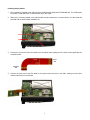
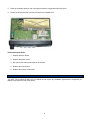
1
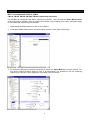
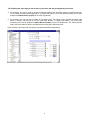
MOT-TVS-2-COM-M Frequency Hopping, Rolling Code Voice Scrambler for Motorola Commercial Series Mobile Radios MOT-VPU-15-COM-M Voice Inversion Voice Scrambler for Motorola Commercial Series Mobile Radios Manual Revision: 2014-05-19 Covers Software Revisions: MOT-COM: 2.95 and Higher Covers Hardware Revisions: MOT-COM: 7348D and Higher This manual supports the following Midian scramblers: MOT-TVS-2-COM-M & MOT-VPU-15-COM-M This manual supports the following radios: North America: CM-300, PM-400 (4-key version) EMEA Region: CM-160, CM-360 Asia: GM-3688 Latin America: EM-400 1 SPECIFICATIONS Operating Voltage Operating Current Operating Temperature Frequency Response Input Impedance Carrier Suppression Audio Output Impedance Tone Distortion 3.3 VDC 8 mA -30 - +60 C 300-2100 Hz 200 k 60 dB < Peak Voice 75 <1% Encryption Specifications TVS-2: Encryption Sequences TVS-2: Random Number Generator TVS-2: Sequence Length (est.) +40 Trillion 64 bits 84 billion years VPU-15: Inversion Codes Available 37 GENERAL INFORMATION The MOT-TVS-2-COM series is a high-level rolling code scrambler that plugs into the Motorola Commercial series radios. The TVS-2 uses hopping type rolling code encryption for higher security rather than sweeping code type and offers 4 user-programmable hop rates and is down gradable to voice inversion. The scrambler is capable of features such as ANI, ENI, OTAR, Deadbeat Disable, Spy, and more when using Midian’s Kryptic Signaling format with the CAD-300/DDU-300/TRC-300. The MOT-VPU-15-COM series is an entry level voice inversion scrambler that plugs into the Motorola Commercial series radios. The scrambler is capable of features such as ANI, ENI, OTAR, Deadbeat Disable, Spy, and more when using Midian’s Kryptic Signaling format with the CAD-300/DDU-300/TRC-300. For more detailed information on the scramblers’ features, troubleshooting and system information please reference the TVS-2 Technical Reference Manual. INSTALLATION OVERVIEW 1. Test the radio for functionality. 2. Program the radio per the Radio Programming Section of this manual. 3. Install the scrambler into the radio per the Hardware Installation Section of this manual. 4. Program the scrambler per the Product Programming Section of this manual. Note: Midian is not responsible for any damage/loss resulting from the use of Midian’s products. 2 RADIO PROGRAMMING MOT-TVS-2-COM-M & MOT-VPU-15-COM-M CM-160, CM-300, EM-400, GM-3688, PM-400 Programming Instructions It is necessary to program the radio before installing the scrambler. This is because the Option Board Feature of the radio must be enabled in order to program the scrambler using a RIB box and to hear confirmation beeps from the radio after programming the scrambler. 1. Upon starting the CPS programmer, click on View->Expert. 2. In the Option Board Window select “Advanced Option Interface” as the “Option Board Type”. 3. For each personality where scrambler functionality is desired, the Option Board box must be checked. You may wish to enable the option board on some or all personalities. This depends on how the scrambling feature will be controlled. This is explained in more detail in the next section. 3 The following two steps apply to the accessory connector and may be skipped by most users. 4. An accessory pin may be used to control the transmit mode of the scrambler between scramble and clear. This is useful in remote control applications. To enable this feature, one of the radio accessory pins must be assigned to Option Board 1 (Input) via the CPS programmer. 5. An accessory pin may be used to initiate an emergency ANI. This allows for an external emergency foot switch or button, and frees-up one of the radio front buttons. To enable this feature, one of the radio accessory pins must be assigned to Option Board 2 (Input) via the CPS programmer. The switch must be held in the active state for about 2 seconds before an emergency ANI will be sent. Note: Accessory pin features do not require any special scrambler programming. 4 MOT-TVS-2-COM-M & MOT-VPU-15-COM-M CM-360 Programming Instructions It is necessary to program the radio before installing the scrambler. This is because the Option Board Feature of the radio must be enabled in order to program the scrambler using a RIB box and to hear confirmation beeps from the radio after programming the scrambler. 1. Upon starting the CPS programmer, click on View->Expert. 2. In the Option Board Window select “Advanced” as the “Option Board Type”. 3. For each personality where scrambler functionality is desired, the Option Board box must be checked. You may wish to enable the option board on some or all personalities. This will depend on how the scrambling feature will be controlled. This is explained in more detail in the next section. 5 HARDWARE INSTALLATION Be certain to follow standard anti-static procedures when handling any of Midian’s products. Radio Firmware: Before installing the scrambler, check the radio firmware version. This is determined by reading the radio using the CPS. The scrambler has been tested with radio firmware versions R03.00.03 and R03.00.04. If the radio has an older version, it may need to be upgraded to ensure proper operation with the scrambler. Disassembling the Radio: Please consult the booklet included with the option board installation kit COM Option B (Motorola P/N PMLN4623A) for illustrations and more detailed installation instructions. Equipment required: Small flat blade screwdriver (4 mm maximum). Torx style screwdriver, size T-10. Small Phillips screwdriver. 1. Disconnect power. 2. Use a flat blade screwdriver to pry the volume control knob away from the front cover. This is best done from the bottom of the knob. Pull off the volume control knob. 3. Locate the two notches on the bottom which keep the control head in place. Use a flat blade screwdriver to pry the control head away from the chassis. 4. Carefully separate the control head from the chassis and remove the flat cable connecting the two from the chassis. 5. Use a flat blade screwdriver to pry the sides of the plastic cover away from the T-shaped mounting bosses on the sides of the radio. 6. Use a flat blade screwdriver to pry the plastic cover away from the tab on the back of the radio. 7. Remove the plastic cover. 8. Insert a flat blade screwdriver into the gap between the main shield and chassis near the speaker cutout area to lift the main shield from the chassis. 6 Installing the Scrambler: 1. The scrambler is installed in the radio using the COM Option B (Motorola P/N PMLN4623A). The COM Option B includes 4 metal stand-offs, 4 screws and a 28-pin flex cable. 2. Remove the 3 screws located in the option board area and replace the 3 screws with the 3 of the stand-offs provided with the option board installation kit. 3. Connect the curved end of the flex cable to the scrambler board making sure the silver contact pads face the scrambler board. Radio Side Scrambler Side 4. Connect the other end of the flex cable to the option board connector in the radio, making sure the silver contact pads face the circuit board. 7 5. Place the scrambler board on top of the spacers with the component side facing down. 6. Secure the board using the 3 screws provided in the installation kit. Reassembling the Radio: 1. Replace the main shield. 2. Replace the plastic cover. 3. Re-connect the control head cable to the chassis. 4. Replace the control head. 5. Replace the volume control knob. HARDWARE ALIGNMENT The MOT-TVS-2-COM-M & MOT-VPU-15-COM-M do not require any hardware adjustments or alignments, as Midian has preset the levels at the factory. 8 PRODUCT PROGRAMMING Install the MPS software if you have not done so already. The MOT-TVS-2-COM & MOT-VPU-15-COM series is programmable through the radio using the radio programming cables and the MPS software. Start the MPS software. From the product selection screen on the MPS software, locate and select MOT-TVS-2PRO or MOT-VPU-15-PRO and the desired model and click OK. The following table shows the proper MPS selection based upon the model scrambler ordered. PRO-M (MDC Mobile) PRO-ME (5-Tone or MPT Mobile) MOT-TVS-2-COM-M or MOT-VPU-15-COM-M MOT-TVS-2-COM-M, MOT-VPU-15-COM-M for CM-360 Configure the programming software by selecting File->Preferences. Select the appropriate COM port. If using the RIB box, make certain there is a check mark next to ‘Rib Box Enable’ by clicking on it. Set the parameters of the software to fit the application. If any clarifications on a feature are required, move the mouse cursor over the feature name until the question mark appears and right click, an on-line help for that feature will be shown. On the radio tab it is necessary to select the proper Radio Model. If the correct product was selected in the step above then it will be preset in the default file. The following table indicates the proper Radio Model Selection for the scrambler ordered: (A) MDC/LTR Mobile (6) 5-Tone or MPT Mobile MOT-TVS-2-COM-M, MOT-VPU-15-COM-M MOT-TVS-2-COM-M, MOT-VPU-15-COM-M for CM-360 After entering the parameters, save the file by going to File - Save As. Enter the file name in the File Name block and click Save. Saving the file will allow for quick and easy reprogramming of units. Turn power on to the radio and then the RIB. Click ProgramUnit! in the MPS software. You will hear 1-3 beeps from the radio if programmed successfully. To read the parameters from the scrambler, Click on ReadUnit!. The radio and RIB should be powered down for 3 seconds after reading or programming. Important Note: Do not attempt to ‘clone’ the scrambler by reading one and then programming another. When the scrambler is read, the security codes will be read out as zeroes. If another scrambler is then cloned with this information, the scramblers will be incompatible because they have different security codes. To ensure scramblers communicate with each other, program them from a saved file. 9 OPERATION Option Board Feature: Enabling the option board feature tells the radio to report events such as button press, PTT press, carrier detect, etc. to the option board. This feature enables communication between the option board and the radio. When controlling the scrambler with a radio button, it is absolutely required to enable this feature on all channels. For scrambling on a per channel basis only enable the option board on scrambled channels and the power up mode of the scrambler should be Scramble. On display models, the following icon appears on the LCD when option board mode is on: Mode Selection: Mode selection means a method of turning the scrambler on and off. In the MOT-TVS-2-COM and MOT-VPU-15-COM series there are three ways of doing this: Per-Channel Scramble On/Off: To use this feature each channel that is designated as a Scrambled channel should have the Option Board Feature box enabled in the radio programming software. Channels that are designated as Clear should NOT have the Option Board feature box enabled. Additionally the Power-Up State in the MPS software should be set to Scramble. When using Per-Channel Scrambling, a button should NOT be programmed for Mode Select in the MPS software. Option Board On/Off Button: The scrambling function may also be controlled by assigning a button to “Option Board” via the CPS programmer. This button may then be used to turn the scrambler on and off. This mode of operation requires that the Power-up Mode of the scrambler be set to Scramble. For the two above modes, the option board icon is displayed when scrambling is enabled. When the icon is not displayed, the scrambler board is completely disabled. It cannot decode scrambled audio, nor can it respond to commands from a CAD-300 or DDU-300. Scramble On/Off Button: To use this feature each channel should have the Option Board Feature box enabled in the radio programming software. The desired button should be programmed to no function in the radio programming software. In the MPS software on the Radio tab in the Button Assignment area set the desired button to “Mode Select”. Pressing and releasing this button will toggle the mode of the scrambler between scramble and clear. A medium tone followed by a high tone indicates the scrambler is in Scramble mode and a medium tone followed by a low tone indicates the scrambler is in Clear mode. Code Selection: The TVS-2 or VPU-15 can have up to 4 different codes programmed. Code Selection Button: To use this feature multiple security codes must be programmed into the TVS-2 or VPU15 scrambler. The desired button should be programmed to no function in the radio programming software. In the MPS software on the Radio tab in the Button Assignment area set the desired button to “Code Select”. Pressing and releasing this button will step the scrambler to the next security code. The scrambler will emit a number of beeps corresponding to the code number the scrambler stepped to (i.e. 2 beeps equals security code 2). The maximum number of codes is 4. 10 TECHNICAL NOTES Radio Compatibility: Midian has taken the utmost care to ensure the option board integrates into the radio with minimal impact to the features of the radio. However, some features may not be available in the radio when an option board is used. If a feature is not available, please contact Midian to see if the feature can be added. Radio Firmware: Midian recommends having the latest firmware in the radio when installing the scrambler. However, it should be noted that occasionally firmware updates may cause a conflict with proper option board/radio communications. This may appear that the scrambler is not working properly, but it is a conflict in the serial communication between the option board and radio. If this happens it will be necessary to go back to the original firmware revision. Please note that firmware versions between the EMEA region and the Asia and America regions might be different. Scan: Midian strongly recommends not using the radio’s Scan function when using voice scramblers. First of all synchronization packets will most likely not be decoded by the receiving radios, as the receiving radio may be looking at a different channel when sync is transmitted. Additionally if using a combination of scrambling on a perchannel basis and a mode select button to control the state of the scrambler, when the scan function is used the radio will ignore the button. This is best resolved by using per-channel scrambling OR a mode select button, but not both. If using scan and a mode-select button the Option Board Feature box in the radio programming section must be enabled on all channels. Known Issues: 1. The radio must be off for a full 3 seconds prior to being turned on or the scrambler cannot reset properly resulting in malfunction. 2. The "Enable LCD Message" option in the MPS software should not be enabled due to problems in the radio. It will cause the backlight to turn off when the mode/code is displayed and all of the icons will disappear. 3. Not all button assignments available via the MPS software work with this radio. The "Combo (press & hold)" and "Emerg (press & hold)" are not supported on the P1, P2, and P3 buttons when using Enhanced Integration. Only those assignments listed below are valid: No Function · Mode Select · Combo · Code Select · Emergency Emergency (press & hold) (on P3 long press only) When assigning buttons to the scrambler via the MPS software, the actual assignments vary from what is selected on the screen. Please refer to the following list, which shows the actual assignment that will take place for each possible selection: SELECTED BUTTON P1 P2 P3 P4 ACTUAL BUTTON P2 short press P2 long press P3 short press P3 long press 4. The "Enable Wired PTT" function on the "Radio" screen of the MPS software is obsolete. This box should never be checked. 5. Use of the System Scan feature of the radio has been known to cause a problem whereby the transmitter stays on the air 3 seconds after PTT is released. Checking the "Reserved Function" box on the "Advanced" screen of the MPS software works around this radio problem. 6. Upon power-up, the radio does not always report the state of the accessory pins to the option board. It may be necessary to toggle the state of these inputs once after power-up to ensure correct operation. 11 MIDIAN CONTACT INFORMATION MIDIAN ELECTRONICS, INC. 2302 East 22nd Street Tucson, Arizona 85713 USA Toll-Free: 1-800-MIDIANS Main: 520-884-7981 E-mail: [email protected] Web: www.midians.com 12 1 2 3 4 5 6 A A Vdd Vdd Vdd COC2 C2 .01u COR33 R33 10K OPT ENA PIC10602 PIC10601 COC109 C109 100p COC106 C106 GND 20 PIIC1020 19 PIIC1019 29 PIIC1029 GND 100p 30 PIIC1030 31 PIIC1031 GND COC6 C6 39p 32 PIIC1032 34 PIIC1034 GND 15 PIIC1015 COR4 R4 1.8M 14 PIIC1014 PIR402 COC34 C34 .001u RESET PIC3401 PIC3402 VAN 150p GND PIR3901 COR38 R38 COR39 R39 1K PIR3802 PI C801 1 C32 COC32 PIR3801 1K PIR3902 42 39 40 NC3 NC4 IRQ OSC1 PIIC1037 19 PIIC2019 VAN PIR802 PIC1001 COR21 R21 75K PIR2101 COR22 R22 PIR2102 PIR2201 COC11 C11 .0068u PIC1102 COR6 R6 10K PIC1101 9 PIIC709- 10 PIIC7010+ PIR601 PIR1801 PIC301 PIC302 COR18 R18 C3 COC3 .01u VAN 8.2K 8 PIIC708 COIC7:3 IC7:3 LMV324 VAN 12 PIIC7012 COR20 R20 36K PIR2001 + PIR2002 PIC1202 PIC1201 COP3 P3 A0 A2 A1 7 PI C203 A1 A2 20 PIIC2020 PIR1502 GND Vdd PI C401 PIC2301 4 PIIC404TRG PIC2201 PIC2102 PIC2401 PIC2402 PIC2101 COC20 C20 150p PI C202 PIR2802 COC24 C24 470p PIR2801 11 PIIC601112 PIIC6012+ COTP1 TP1 10 PIIC9014X 8 PIIC508 COR24 R24 10K PIR2402 COC29 C29 .01u COR23 R23 30K PIC2902 PIC2901 PIR2302 PIR2401 2 PIIC602- PIR2301 1 PIIC601 3 13 X1 PIIC9013 PIIC603+ COIC9:1 IC9:1 74HC4053 PIR4002 VAN PIC1402 PIC1401 C14 COC14 .1u PIC1501 PIC1502 C15 COC15 .001u PIIC6010 PIC1602 PIC1601 C16 COC16 .1u + PIC30 2 COC30 C30 4.7u PIC3502 PIC3501 PIR3101 C PIC2701 COC27 C27 22p PIC2702 COC8 C8 * PIR4001 TX OUT PIR3102 VAN PIC802 PIC30 1 COR31 R31 0R COIC6:1 IC6:1 TLV2375 COR40 R40 4.7K PI C503 PI C506 PI C507 PI C501 PI C505 COC13 C13 39p GND PIC401 PITP101 Y PIIC9015 PIC1302 PIC1301 12 X0 PIIC9012 COC4 C4 .0047u PIC402 A 14 COC38 C38 * GND PI C901 11 GND COIC5 IC5 LTC1069 15 3 OUT PIIC403 GND COIC4 PI C402 IC4 MIC1555 COR28 R28 4.7K PIC3802 PIC3801 VS 5 PIIC405THS COC21 C21 39p 1 PIIC201 GND VAN COC25 C25 22p PIR1501 GND GND PIC2202 4 PIIC504 COIC9:2 IC9:2 74HC4053 R15 COR15 10K1% PIR1401 C31 COC31 100p PIC2502 PIC2501 COC22 C22 82p PI C9010 PIIC902Y0 R14 COR14 10K1% PIR1802 GND PIY101 COY1 Y1 3.58 MHz COC26 C26 22p 36 1 2 B PIIC1036 B PIR1402 PIC3102 PIC3101 PIY102 PIC2601 PIC2602 PI C502 PIIC901 Y1 PROG OUT 37 PI C2018 PI C2014 PROG IN 8 Vdd 10 COIC7:4 IC7:4 LMV324 C12 COC12 .001u PIR3201 GND GND 14 - PIR3202 PIC2302 PI C2010 PI C205 PI C206 PI C2017 PIIC7014 13 PIIC7013 GND PIC2002 PIC2001 COR16 R16 36K PIR2202 Vdd COR7 R7 100K PIR1602 1.2M PIR1601 PIR1901 COIC2 IC2 16F716 PI C207 COR19 R19 56K PIR1902 PI C107 PI C204 PI C2013 PI C201 PI C2012 PI C208 PI C209 A0 5 PIIC305 2 PIP302 3 VDD GND COC18 C18 .1u 21 18 16 PIIC2016 COIC6:2 IC6:2 TLV2375 SO 6 PIIC306 COC23 C23 22p 10 VDD ORG PIC1802 PIC1801 1 A4 5 PIIC605+ GND 15 PIIC2015 SI 7 28 OSC1 7 PI C1035 PI C103 PI C104 PI C105 PI C106 6 PIR1302 COC17 C17 .001u B3 GND PIC1002 PIR602 PIIC108 OSC2 9 PIC1701 PIC1702 PIIC607 PIR1702 * PIR1202 COR13 R13 6 COR9 R9 * MAX809-S 3 2 PIIC803 V+ OUT PIIC802 B0 PIIC307 PIP301 A3 COR8 R8 PIR1201 36K COC10 C10 .0068u PIR901 PIIC1021 B7 COIC7:2 IC7:2 LMV324 PIQ10D COQ1 Q1 BSS 74HC4053 Vdd COIC8 IC8 PIC3201 PIC3202 PIQ10S A5 B2 7 Vdd +VIN PIC901 PIIC606- PIR902 GND PIC902 PIR1301 COR17 R17 27K PIIC707 C C4 NC1 2 PIC1 302 100p PIR1001 COIC9:3 PI C906 IC9:3 PIR201 PIR801 COC113 C113 PIIC1028 14 * TDO SCLK 22 TCMP OSC2 DISC IN COC33 C33 PIR1002 2 PIIC102 Vdd 5 6 Z PIIC904 8 GND PIIC908 7 VEE PIIC907 33 PIIC1033 COR12 R12 62K 8 E\ 4 PIQ10G PIR1701 5 PIIC705 + PIIC1022 GND PIR2901 A3 GND 6 NC2 PIIC308 COR32 R32 10K A7 17 PIC3 02 PIC3 01 PIC1 301 PIIC903 Z1 COC9 C9 .0068u COR10 R10 18K PIR1101 4 3 PIC501 PIIC706 - PIR102 RDI VCC PIR702 RES 12 PIIC905 Z0 PIR1102 44 PIIC1044 B1 PIR101 VCC 5 100K VSS PIR3602 PI C909 PI C9016 C COR11 R11 GND 16 6 PIR3601 PIR701 COR29 R29 4.7M B5 9 41 PIIC1041 VSS RX IN 750K 16 25 PIIC1025 23 PIIC1023 PIIC1016 PIR4101 A4 COC7 C7 .0068u COR1 R1 0R 4 PIR2902 5 COR36 R36 COR41 R41 * 3 PIC701 PIC702 COR2 R2 1.2M PIR202 PIIC304 PIIC1010 27 PIIC1027 B6 11 GND 10 2 PIR502 COC5 VAN C5 39p PIC502 B7 B4 PIR501 COIC7:1 IC7:1 LMV324 PI C701 11 * D7 TCAP COC1 C1 1 PIIC701 3 PIIC703 + SS B0 PIR301 COR5 R5 4.7K 3 PIIC303 GND SCK PIR4102 COC19 C19 .1u 11 PIIC1011 17 PIIC1017 MOSI 35 PIR302 PI C704 PIC1902 PIC1901 PIIC302 8 CS MISO 13 PIC101 PIC102 PIC2801 2 PIIC702 - C6 B6 PIC2802 300K 4 TX IN COR3 R3 12 C5 7 COC28 C28 .001u A6 Vdd 4 Vdd MCLR PIR401 PIIC1012 NC1 C1 C3 1 2 PIC601 PIC602 B4 B2 1 PIIC101 GND PIIC301 B3 COR35 R35 10K PIR3502 COC108 C108 100p 13 1 PIC10901 PIC10902 PIR3501 PIIC1013 2 CLK COIC1 IC1 68705HS B5 5 PIC10801 PIC10802 100p B1 Vdd COIC3 IC3 CAT93C46 1 MOSI COC107 C107 PIR3702 7 PIC10701 PIC10702 PIR3701 C2 Vdd COC37 C37 * 18 PIIC1018 6 MISO PIC3701 PIC10501 C105 COC105PIC3702 PIC10502 100p 9 PIIC109 C7 PIR3 02 COR37 R37 0R 3 PTT B 24 PIIC1024 C C0 VDD COPAD5 PIPAD401 COPAD4 PIPAD301 B COPAD3 PIPAD201 A COPAD2 RDY 26 PIIC1026 PIPAD501 VPP PI C1043 PI C1038 PI C1040 PI C1039 PI C1042 GND D 38 PIC201 43 PIC202 PIR3 01 COIC6:5 IC6:5 TLV2375 4 PIIC604 VCC 8 PIIC608 1/2SHDN 9 PIIC609 3/4SHDN 13 PIIC6013 GND PIR4202 PIR4201 COR42 R42 * GND PIC801 R26 COR26 10K C35 COC35 * COC36 C36 0R PIC3602 PIC3601 PIR2602 R25 COR25 39K PIR2502 PIR2501 PIR2601 15 PIIC601514 PIIC6014+ COIC6:3 IC6:3 TLV2375 GND 16 PIIC6016 R30 COR30 0R PIR3001 RX OUT PIR3002 COIC6:4 IC6:4 TLV2375 PIR3402 COR34 R34 * VAN PIR3401 GND D D COtb0sch1 MIDIAN ELECTRONICS, INC. DATE:2006-05-01 DWN BY:DML DESIGN: CJS 1 2 3 4 REV: 2014-05-13 5 APPR MOT-TVS-2-COM-M SCHEMATIC COPYRIGHT © 2014 REV DOCUMENT NAME D-4 CP SHEET PROJECT NUMBER 1 of 1 6 7727 COC18 PAC1802 PAC1801 COR32 PAR3201 PAR3202 COP3 PAIC308PAIC307PAIC306PAIC305 PAC3802 PAIC401 COIC4 COC38 PAC3801 PAIC402 PAP301 PAC2301 PAC2001 PAC2101 PAC2201 PAIC403 COIC3 COR28 COC24 PAR2802 PAC2401 PAC2402 PAR2801 PAIC405 PAIC404 PAR4201 PAR3101 PAC401 PAR2401 COR7 PAR702 PAR701 OR30 CPAR3402 OR34 CPAR3002 PAIC1023 PAIC301PAIC302PAIC303PAIC304 PAIC1011 COPAD3 PAIC1010 PAIC109 PAIC108 PAPAD301 PAIC107 PAIC106 PAIC105 PAIC104 PAIC103 COPAD2 PAIC102 PAIC101 COIC1 PAIC1031 PAVS1031 PAIC1032 PAVS1032 PAVS1033 PAIC1033 COC25 PAC2502 COY1 PAC2501 PAPAD201 PAIVCS1034 PAVISC1035 5PAIVCS1036 PAIVCS1037 PAIVSC1038 8 PAIVSC1039 9PAIVSC104 0PAIVCS1041 PAIVCS1042 PAIVSC1043 3 PAIVSC104 4 PAY101 PAR2901 PAR3501 PAC1701 COR35PAR3502 CPAC1702 OC17 PAR601 PAC301 COR41PAR4102 COC3 PAC302 PAR402 PAVS1011 PAIC6011 PAVS1010 PAIC6010 PAVS108 PAIC608 PAVS109 PAIC609 PAR1401 PAR1601 PAC3401 COR1 PAR101 PAR102 PAIC706 PAR202 PAC502 PAIC707 COC113 PAC11302 PAC11301 COR36 PAR3601 PAIC7013 COIC7 PAIC703 PAC3402 PAC3301 PAIC7014 PAIC702 COC34 PAC3302 PAR901 PAIC803 PAR902 PAIC701 PAIC7012 PAIC704 PAIC705 PAIC7011 PAIC7010 PAIC709 PAIC708 COR17 PAR1501 PAR1502 PAC2801 PAC2802 PAR1801 PAIC9016 COIC9 PAIC9015 PAIC9014 PAIC904 PAIC905 PAIC9013 PAIC9012 PAC701 PAIC906 PAIC9011 PAIC907 PAIC9010 COC7 PAC702 PAIC908 PAIC909 PAR4001 CPAR4002 OR40 PAR1802 COC1 PAC102 COC111 PAC1 102 PAC11101 PAC101 COC35 PAC3501 PAC3502 COC19 PAC11002 PAC11202 CPAC11001 OC1 0 CPAC11201 OC1 2 PAC2701 COC27 PAC2702 COTP1 COP2 PAVS1029 PAP2029 PAVS1030 PAP2030 PAIC505 PAIC506 PAIC507 PAC1901 PAC1902 PATP101 COC13 PAC1301 PAC1302 COIC5 PAIC508 PAP201PA 20 PAP203PA 204PAP205PA 206PAP207PAP208PA 209PA 201 PA 201 PA 2012PA 2013 PA 2014PA 2015PA 2016PA 2017PA 2018PA 2019PA 20 PAV2S10 1PAVS210 2 PAVS2103 PAVS2104 PAVS2105 PAVS2106 PAVS2107 PAVS2108 PAC10801 PAC10701 PAC10501 PAC10901 PAC10301 COC101 PAC10102 PAC10101 PAC10401 PAC2901 CPAC3602 OC36 COC29PAC2902 COR9 COC104 PAC10402 PAC3601 COR19 COC11 COR18 PAR2302 COC15 PAC1502 PAC1201 PAC1501 COR20 OC12 PAR2001 PAR2002 CPAC1202 PAR1701 PAR1702 PAC1102 PAC1101 PAR1902 PAR1901 COR8 PAR802 COC10 PAC1002 PAC1001 PAR801 COC28 COC31PAC3102 COPAR2502 R25 COR23 PAR2301 COR14 COR16 CO COC8 PAC802 PAC3101 PAR2501 COR15 PAC602 COR4 PAR401 COC6 PAC601 PAR3602 COC102 PAC10202 PAC10201 COPAC10802C108 CPAC10702OC107 CPAC10502 OC105 COPAC10902 C109 COPAC10302C103 PAVS1012 PAIC6012 PAVS106 PAIC606 PAVS107 PAIC607 COR22 COR5 PAR502 PAR2101 PAR2102 PAR2201 PAR2202 PAR501 COC33 COIC8 COC106 PAC10602 PAC10601 COC2 PAC202 PAVS105 PAIC605 COR21 COR2 COC5 PAR201 PAC501 PAIC802 PAIC801 PAR3801 PAR3901 PAC201 R29 COC26 OR39 PAY102 COPAR2902 PAC2601 PAC2602 COR38PAR3802 CPAR3902 PAR301 COR3 PAR302 PAR4101 CPAR2602 OR26 PAVS1013 PAIC6013 PAR1402 PAR1602 COR13 PAR1302 PAR1301 PAR1102 PAQ10G PAVS10BCOQ1 COR12 PAVS10C PAR1201 PAR1202 PAQ10D PAIC901 COR11 PAR1101 COC9 COR10 PAVS10E PAQ10S PAC902 PAR1001 PAR1002 PAIC902 PAC901 PAIC903 PAIC201 PAIC2012 PAIC2013 PAIC2014PAIC2015PAIC2016 PAIVSC102717PAIVCS120 18 PAIVSC102919PAIVSC102 20 COR6 PAR602 PAR2601 PAC801 PAVS1015 PAIC6015 PAVS1014 PAIC6014 PAVS104 PAIC604 PAR3301 PAR3302 COR37 PAR3702 PAR3701 PAIC102 PAIC1021PAIC102 PAIC10 9 PAIC10 8 PAIC10 7PAIC1016PAIC10 5 PAIC10 4 PAIC10 3 PAIC10 2 PAPAD401 PAIC1024 PAIC1025 PAPAD501 PAIC1026 COIC6 PAVS1016 PAIC6016 COR33 COC37 PAC3702 PAC3701 PAIC1027 PAIC1028 PAIC1029 PAIC1030 COC4 PAC402 PAR2402 PAR3401 PAR3001 CPAC2302 OC23 CPAC2002 OC20 COC21PAC2102 COC22PAC2202 COIC2 COPAD4 COPAD5 PAVS102 PAIC602 PAVS103 PAIC603 COR24 CPAR4202 OR42 COPAR3102 R31 PAIC2010PAIC209 PAIC208 PAIC207PAIC206PAIC205 PAIC204PAIC203 PAIC202PAIC201 PAVS101 PAP302 PAIC601 COC32 PAC3202 PAC3201 PAIC501 COC14 PAC1401 PAC1402 COC16 PAC1602 PAC1601 PAIC504 PAIC503 PAIC502 PAC3001 PAC3002 COC30 2SVOC 102SVAP