1
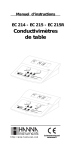
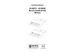
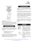
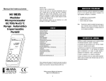
Instruction Manual
EC214
EC215 - EC215R
Bench
Conductivity
Meters
http://www.hannainst.com
These Instruments are in
Compliance with the CE Directives
Dear Customer,
Thank you for choosing a Hanna Instruments Product.
Please read this instruction manual carefully before using the instrument.
This manual will provide you with all the necessary information for the
correct use of the instrument, as well as a precise idea of its versatility
in a wide range of applications.
These instruments are in compliance with
directives.
TABLE OF CONTENTS
PRELIMINARY EXAMINATION ............................................................ 3
PRELIMINARY EXAMINATION
Remove the instrument from the packing material and examine it
carefully to make sure that no damage has occurred during shipping.
If there is any damage, notify your dealer.
Each meter is supplied complete with:
• Conductivity Probe (HI76300 for EC 214, HI76303 for EC 215
and EC 215R);
• Instruction Manual;
• 12VDC adapter (HI710005 or HI710006);
• Dust cover.
Note: Save all packing material until you are sure that the instrument
functions correctly. All defective items must be returned in the
original packing with the supplied accessories.
GENERAL DESCRIPTION .................................................................... 3
FUNCTIONAL DESCRIPTION EC 214 ................................................... 4
SPECIFICATIONS EC 214 .................................................................. 5
FUNCTIONAL DESCRIPTION EC 215 ................................................... 6
SPECIFICATIONS EC 215 .................................................................. 7
OPERATIONAL GUIDE ....................................................................... 8
CALIBRATION ................................................................................ 10
CONDUCTIVITY VS. TEMPERATURE CHART ......................................... 13
DETERMINATION OF THE TEMPERATURE
COEFFICIENT OF A SOLUTION (EC 215 & EC 215R) ........................... 14
PROBE MAINTENANCE ................................................................... 15
ACCESSORIES ............................................................................... 16
WARRANTY ................................................................................... 18
CE DECLARATION OF CONFORMITY .................................................. 19
2
GENERAL DESCRIPTION
EC 214 and EC 215 are digital bench-top multirange conductivity
meters designed for simplicity of use in measuring electrical conductivity in liquids.
Four ranges of conductivity measurements are provided to cover every
application from deionized water to brine.
The calibration is made simple through the easy-to-operate front
panel knob for slope adjustment.
The conductivity probe does not require re-calibration when switching
from one range to another.
The probe is made of glass with 4 platinum rings that are corrosion
resistant. It is also suitable for measuring conductivity of liquids in
small sample sizes, and comes with a 1 m (3.3') cable.
The temperature effect can be compensated through a knob on the
front panel of EC 214.
With EC 215, the 4-ring probe has a built-in temperature sensor that
automatically compensates for temperature changes in the liquid
tested. The temperature coefficient can be adjusted from 0 to 2.5%
through a knob on the front panel.
It is also available a model with recorder output feature: EC 215R.
3
FUNCTIONAL DESCRIPTION EC 214
SPECIFICATIONS EC 214
Range
Resolution
Accuracy
(@20°C / 68°F)
Typical EMC
Deviation
Calibration
Temperature
Compensation
Probe
Power Supply
Environment
1)
2)
3)
4)
5)
6)
7)
Liquid Crystal Display (LCD)
Conductivity calibration knob
8)
9)
10)
11)
Temperature setting knob for manual compensation
ON/OFF switch
Power adapter socket
Probe connector
Dimensions
Weight
0.0 to 199.9 µS/cm
0 to 1999 µS/cm
0.00 to 19.99 mS/cm
0.0 to 199.9 mS/cm
0.1 µS/cm
1 µS/cm
0.01 mS/cm
0.1 mS/cm
±1% Full Scale
(excluding probe error)
±1% Full Scale
Manual single point through front knob
Manual from 0 to 50 C
with ß fixed at 2%/ C
HI 76300
platinum 4-ring conductivity probe
with 1m (3.3') cable
(included)
12 VDC adapter
(HI710005 or HI710006 included)
0 to 50 C (32 to 122 F);
0-95% RH non-condensing
240x182x74 mm (9.4x7.1x2.9")
1.0 Kg (2.3 lb.)
199.9 µS key, to select the range 0.0 to 199.9µS/cm
19.99 mS key, to select the range 0.00 to 19.99 mS/cm
199.9 mS key, to select the range 0.0 to 199.9mS/cm
1999 µS key, to select the range 0 to 1999µS/cm
COND/ C key, to select conductivity reading or temperature setting for manual compensation
4
5
FUNCTIONAL DESCRIPTION EC 215
SPECIFICATIONS EC 215
Range
Resolution
Accuracy
(@20°C / 68°F)
Typical EMC
Deviation
Calibration
Temperature
Compensation
Probe (included)
Analog Output
(EC 215R only)
1) Liquid Crystal Display (LCD)
2) Conductivity calibration knob
3) 199.9 µS key, to select the range 0.0 to 199.9µS/cm
4) 19.99 mS key, to select the range 0.00 to 19.99 mS/cm
5) 199.9 mS key, to select the range 0.0 to 199.9mS/cm
6) 1999 µS key, to select the range 0 to 1999µS/cm
7) Temperature Coefficient setting knob
8) ON/OFF switch
9) Power adapter socket
10) Probe connector
11) Analog Output (EC 215R only)
6
Analog Output
Accuracy
Analog Output
Resolution
Power Supply
Environment
Dimensions
Weight
0.0 to 199.9 µS/cm
0 to 1999 µS/cm
0.00 to 19.99 mS/cm
0.0 to 199.9 mS/cm
0.1 µS/cm
1 µS/cm
0.01 mS/cm
0.1 mS/cm
±1% Full Scale
(excluding probe error)
±1% Full Scale
Manual at single point, through front knob
Automatic from 0 to 50 C
with adjustable β from 0 to 2.5%/ C
HI 76303
platinum 4-ring conductivity probe
with temperature sensor and 1m (3.3') cable
0 to 5VCC not isolated analog output - 20mA max
Range
Output
0.0 to 199.9µS/cm
0 to 5 VCC
0 to 1999µS/cm
0 to 5 VCC
0.00 to 19.99mS/cm
0 to 5 VCC
0.0 to 199.9mS/cm
0 to 5 VCC
0.1% of maximum displayed value
(EC 215R only)
±2.5 mV
(EC 215R only)
included
12 VDC power adapter (included
included)
0 to 50 C (32 to 122 F);
0-95% RH non-condensing
240x182x74 mm (9.4x7.1x2.9")
1.0 Kg (2.3 lb.)
7
OPERATIONAL GUIDE
Power connection
Plug the 12VDC adapter (HI710005 or HI710006) into the power
supply socket (#10 on page 4; #9 on page 6).
Note: make sure the main line is protected by a fuse.
Probe connection
Connect the conductivity probe to the socket provided (#11 on page
4; #10 on page 6).
Note: Make sure that the instrument has been calibrated before
taking conductivity measurements (see calibration paragraph).
Note: If possible, use plastic beakers to minimize EMC interferences.
TAKING CONDUCTIVITY MEASUREMENTS WITH EC 214
• switch the instrument on by pressing the ON/OFF
key.
• Immerse the probe in the solution submerging
the holes of the sleeve (0.5 cm below). Tap the
probe lightly on the bottom of the beaker to
remove any air bubbles trapped inside the sleeve.
Take the temperature of the solution with a
CHECKTEMP or a glass thermometer.
• Press the “COND/ C” key to select temperature
setting.
• Adjust the “TEMPERATURE” knob to display the temperature of the
solution on the LCD.
Note: If the display shows "1", there is an over-range condition.
Select the next higher range.
• Allow a few minutes for the reading to stabilize. The LCD will
display the temperature compensated conductivity reading.
TAKING CONDUCTIVITY MEASUREMENTS WITH EC 215
• switch the instrument on by pressing the ON/OFF
key.
• Immerse the probe in the solution submerging
the holes of the sleeve (0.5 cm below). Tap
the probe lightly on the bottom of the beaker
to remove any air bubbles trapped inside the
sleeve.
• Adjust the "TEMPERATURE COEFFICIENT" knob to the temperature
coefficient value of the solution (see determination of the temperature coefficient of a solution paragraph).
• Select the appropriate conductivity range.
Note: If the display shows "1", there is an over-range condition.
Select the next higher range.
• Allow a few minutes for the reading to stabilize. The LCD will
display the temperature compensated conductivity reading.
• Press the “COND/ C” key to select conductivity
reading.
• Select the appropriate conductivity range.
8
9
PROCEDURE FOR EC 214:
0
703
HI
If you are measuring in the mS ranges, calibrate the meter using
HI7030 (or HI8030) conductivity solution (12.88 mS @ 25 C) or
HI7034 (or HI8034) conductivity solution (80 mS @ 25 C). For the
µS ranges, use HI7031 (or HI8031) conductivity solution (1413 µS
@25 C) when calibrating in the range from 0 to 1999 µS or
HI7033 (or HI8033) conductivity solution (84 µS @ 25 C) when
calibrating in the range from 0 to 199.9 µS.
Choose a solution with a conductivity value close to the solution to be
measured.
Rinse the probe thoroughly in distilled water. This is to minimize
contamination of the calibration solution and secure higher accuracy.
When possible, use plastic beakers to minimize any EMC interferences.
• Pour a small quantity of the conductivity
solution, e.g. HI7030 or HI8030 (12.88
mS/cm @ 25 C), into a plastic beaker.
• Immerse the probe in the solution submerging
the holes of the sleeve (0.5 cm below). Tap
the probe lightly on the bottom of the beaker
to remove any air bubbles trapped inside the
sleeve. Take the temperature of the solution
with a CHECKTEMP or a glass thermometer.
• Press the “COND/ C” key to select temperature
setting.
• Adjust the “TEMPERATURE” knob to display the temperature of
the solution on the LCD.
10
• All subsequent measurements will be referenced to 25 C (77 F).
• To reference the measurements to 20 C (68 F), adjust the “CALIBRATION” knob to read (on the LCD) the value of the buffer
solution at 20 C (68 F), e.g. 11.67 mS/cm. See conductivity vs.
temperature chart.
• Calibration is now complete and the instrument is ready for use.
0
INITIAL PREPARATION
7 03
The instrument should be re-calibrated at least once a month, or
when the probe is changed.
• Press the “COND/ C” key to select conductivity
reading and select the appropriate range:
"199.9 µS"
for HI7033/HI8033,
"1999µS"
for HI7031/HI8031,
"19.99 mS"
for HI7030/HI8030,
"199.9 mS"
for HI7034/HI8034.
Note: If the display shows "1", there is an over-range condition.
Select the next higher range.
• Allow a few minutes for the reading to stabilize and adjust the
“CALIBRATION” knob to read (on the LCD) the value of the buffer
solution at 25 C (77 F), e.g. 12.88 mS/cm.
PROCEDURE FOR EC 215:
HI
CALIBRATION
• Pour a small quantity of the conductivity
solution, e.g. HI7030 or HI8030 (12.88
mS/cm @ 25 C), into a plastic beaker.
• Immerse the probe in the solution submerging
the holes of the sleeve (0.5 cm below). Tap
the probe lightly on the bottom of the beaker
to remove any air bubbles trapped inside the
sleeve.
• Adjust the "TEMPERATURE COEFFICIENT" knob to 2%/ C.
11
• Select the appropriate range:
"199.9 µS"
for HI7033/HI8033,
"1999µS"
for HI7031/HI8031,
"19.99 mS"
for HI7030/HI8030,
"199.9 mS"
for HI7034/HI8034.
Note: If the display shows "1", there is an over-range condition.
Select the next higher range.
• Allow a few minutes for the reading to stabilize and adjust the
“CALIBRATION” knob to read (on the LCD) the value of the buffer
solution at 25 C (77 F),e.g. 12.88 mS/cm.
CONDUCTIVITY VERSUS
TEMPERATURE CHART
The conductivity of an aqueous solution is the measure of its ability to
carry an electrical current by means of ionic motion.
The conductivity invariably increases with increasing temperature.
It is affected by the type and number of ions in the solution and by
the viscosity of the solution itself. Both parameters are temperature
dependent. The dependency of conductivity on temperature is expressed as a relative change per degree Celsius at a particular
temperature, commonly as percent per C.
Since a small difference in temperature causes a large change in
conductivity, the readings are usually normalized at 25 C.
C
• All subsequent measurements will be referenced to 25 C (77 F).
• To reference the measurements to 20 C (68 F), adjust the “CALIBRATION” knob to read (on the LCD) the value of the buffer
solution at 20 C (68 F), e.g. 11.67 mS/cm. See conductivity vs.
temperature chart.
• Calibration is now complete and the instrument is ready for use.
0
5
10
15
16
17
18
19
20
21
22
23
24
25
26
27
28
29
30
31
F
32
41
50
59
60.8
62.6
64.4
66.2
68
69.8
71.6
73.4
75.2
77
78.8
80.6
82.4
84.2
86
87.8
HI 7030
HI 8030
HI 7031
HI 8031
HI 7033
HI 8033
HI 7034
HI 8034
HI 7035
HI 8035
(µS/cm)
(µS/cm)
(µS/cm)
(µS/cm)
(µS/cm)
7150
8220
9330
10480
10720
10950
11190
11430
11670
11910
12150
12390
12640
12880
13130
13370
13620
13870
14120
14370
776
896
1020
1147
1173
1199
1225
1251
1278
1305
1332
1359
1386
1413
1440
1467
1494
1521
1548
1575
64
65
67
68
70
71
73
74
76
78
79
81
82
84
86
87
89
90
92
94
48300
53500
59600
65400
67200
68500
69800
71300
72400
74000
75200
76500
78300
80000
81300
83000
84900
86300
88200
90000
65400
74100
83200
92500
94400
96300
98200
100200
102100
104000
105900
107900
109800
111800
113800
115700
117700
119700
121800
123900
HI 7039
HI 8039
(µS/cm)
2760
3180
3615
4063
4155
4245
4337
4429
4523
4617
4711
4805
4902
5000
5096
5190
5286
5383
5479
5575
EC 214 manually compensates for temperature differences with a
fixed ß at 2%.
EC 215 automatically compensates for temperature differences with a
built-in circuitry. A knob is provided to adjust the temperature coefficient manually from 0% (without compensation) to 2.5% per degree
Celsius.
12
13
DETERMINATION OF THE TEMPERATURE
COEFFICIENT OF A SOLUTION
(EC 215 & EC 215R)
• Immerse the probe into a sample of the solution and adjust the
“TEMPERATURE COEFFICIENT” knob to 0% (i.e. no compensation).
• Condition the sample and probe at 25 C and note the conductivity
reading C25.
• Condition the sample and probe to a temperature t C which is
approximately 5 C to 10 C different from 25 C and note the
conductivity reading Ct.
• The temperature coefficient ß of the solution is calculated with
the formula:
(Ct - C25)
ß = 100 x --------------------------(t - 25) x C25
PROBE MAINTENANCE
Rinse the probe with tap water after
every series of measurements. If a
more thorough cleaning is required,
remove the sleeve and clean the
probe with a cloth or a nonabrasive
detergent.
After cleaning the probe, re-calibrate
the instrument.
The four ring platinum probe body
is in glass. For this reason great
care while handling the probe must
be taken.
The above procedure is suitable for determining the temperature
coefficient in the laboratory where the temperature of the solution can
be determined and controlled. If this is not possible, e.g. during onsite measurements, the following procedure should be used:
• Immerse the probe into the test solution and turn the “TEMPERATURE COEFFICIENT” knob to 0% (no compensation).
• Allow the conductivity reading to stabilize (the reading should not
change by more than ±0.2 mS within 1 minute) and record the
value, C.
• Repeat the procedure with the temperature of the solution changed
by more than 10 C. Wait for the conductivity reading to stabilize.
• Adjust the “TEMPERATURE COEFFICIENT” knob until the display
reads the value C as recorded earlier.
• The value indicated by the knob is the temperature coefficient of
the solution.
14
15
ACCESSORIES
CONDUCTIVITY BUFFER SOLUTIONS:
HI 7030L
HI 7030M
HI 7031L
HI 7031M
HI 7033L
HI 7033M
HI 7034L
HI 7034M
HI 7035L
HI 7035M
HI 7039L
HI 7039M
12880 µS/cm (µmho/cm), 460mL
12880 µS/cm (µmho/cm), 230mL
1413 µS/cm (µmho/cm), 460mL
1413 µS/cm (µmho/cm), 230mL
84 µS/cm (µmho/cm), 460 mL
84 µS/cm (µmho/cm), 230 mL
80000 µS/cm (µmho/cm), 460mL
80000 µS/cm (µmho/cm), 230mL
111800 µS/cm (µmho/cm), 460mL
111800 µS/cm (µmho/cm), 230mL
5000 µS/cm (µmho/cm), 460mL
5000 µS/cm (µmho/cm), 230mL
OTHER ACCESSORIES:
CHECKTEMPC
HI710005
HI710006
Electronic thermometer (range: -50.0 to 150.0 C)
Voltage adapter from 115VAC to 12VDC
Voltage adapter from 230VAC to 12VDC
HI 7400011
HI 740036
HI 740034
HI 740134
HI 76405
Base for bench meters
100mL plastic beakers (6 pcs)
Cap for 100mL beakers (6 pcs)
Dust cover
Electrode holder
CONDUCTIVITY BUFFER SOLUTIONS IN FDA APPROVED
BOTTLES:
HI 8030L
HI 8031L
HI 8033L
HI 8034L
HI 8035L
HI 8039L
12880 µS/cm (µmho/cm), 460 mL
1413 µS/cm (µmho/cm), 460 mL
84 µS/cm (µmho/cm), 460 mL
80000 µS/cm (µmho/cm), 460 mL
111800 µS/cm (µmho/cm),
460 mL
5000 µS/cm (µmho/cm), 460 mL
ELECTRODE CLEANING SOLUTIONS
HI 7061M
HI 7061L
General Cleaning Sol., 230 mL
General Cleaning Sol., 460 mL
ELECTRODE CLEANING SOLUTIONS IN FDA APPROVED
BOTTLES
HI 8061M
HI 8061L
General Cleaning Sol., 230 mL
General Cleaning Sol., 460 mL
CONDUCTIVITY PROBES:
HI 76300
HI 76303
platinum 4-ring conductivity probe with 1m
(3.3') cable (for EC214).
platinum 4-ring conductivity probe with temperature sensor and 1m (3.3') cable (for EC215).
16
17
WARRANTY
CE DECLARATION OF CONFORMITY
All Hanna Instruments meters are guaranteed for two years against
defects in workmanship and materials when used for their intended
purpose and maintained according to instructions. The electrodes
and the probes are guaranteed for a period of six months. This
warranty is limited to repair or replacement free of charge.
Damage due to accident, misuse, tampering or lack of prescribed
maintenance are not covered.
If service is required, contact the dealer from whom you purchased the
instrument. If under warranty, report the model number, date of
purchase, serial number and the nature of the failure. If the repair is
not covered by the warranty, you will be notified of the charges
incurred. If the instrument is to be returned to Hanna Instruments, first
obtain a Returned Goods Authorization number from the Customer
Service department and then send it with shipping costs prepaid.
When shipping any instrument, make sure it is properly packaged for
complete protection.
To validate your warranty, fill out and return the enclosed warranty
card within 14 days from the date of purchase.
All rights are reserved. Reproduction in whole or in part is prohibited
without the written consent of the copyright owner,
Hanna Instruments Inc., 584 Park East Drive, Woonsocket, Rhode
Island, 02895 , USA.
Hanna Instruments reserves the right to modify the design, construction and appearance of its products without advance notice.
Recommendations for Users
Before using these products, make sure that they are entirely suitable for the environment in which they are used.
Operation of these instruments in residential area could cause unacceptable interferences to radio and TV
equipments, requiring the operator to take all necessary steps to correct interferences.
The metal band at the end of the sensor is sensitive to electrostatic discharges. Avoid touching this metal band at all
times.
During calibration of instruments, ESD wrist straps should be worn to avoid possible damage to the sensor by
electrostatic discharge.
Any variation introduced by the user to the supplied equipment may degrade the instruments' EMC performance.
To avoid electrical shock, do not use these instruments when voltages at the measurement surface exceed 24VAC or
60VDC.
Use plastic beakers to minimize any EMC interferences.
To avoid damages or burns, do not perform any measurement in microwave ovens.
MANEC215R2 05/01
h t t p : / / w w w . h a n n a i n s t . c o m