1
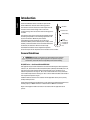
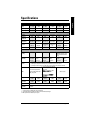
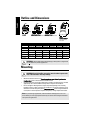
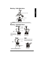
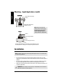
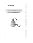
Operation Manual February 2005
xps/xct
ECHOMAX
Echomax XPS/XCT Operation Manual
Questions about the contents of this manual can be directed to:
Siemens Milltronics Process Instruments Inc.
1954 Technology Drive, P.O. Box 4225
Peterborough, Ontario, Canada, K9J 7B1
Email: [email protected]
Copyright Siemens Milltronics Process
Instruments Inc. 2005.
All Rights Reserved
We encourage users to purchase
authorized bound manuals, or to view
electronic versions as designed and
authored by Siemens Milltronics Process
Instruments Inc. Siemens Milltronics
Process Instruments Inc. will not be
responsible for the contents of partial or
whole reproductions of either bound or
electronic versions.
Disclaimer of Liability
While we have verified the contents of this manual
for agreement with the instrumentation described,
variations remain possible. Thus we cannot
guarantee full agreement. The contents of this
manual are regularly reviewed and corrections are
included in subsequent editions. We welcome all
suggestions for improvement.
Technical data subject to change.
MILLTRONICS is a registered trademark of Siemens Milltronics Process Instruments Inc.
Safety Guidelines
Warning notices must be observed to ensure personal safety as well as that of others,
and to protect the product and the connected equipment. These warning notices are
accompanied by a clarification of the level of caution to be observed.
WARNING: relates to a caution symbol on the product, and means that failure to
observe the necessary precautions can result in death, serious injury, and/or
considerable material damage.
WARNING: means that failure to observe the necessary precautions can result in
death, serious injury, and/or considerable material damage.
CAUTION: means that failure to observe the necessary precautions can result in
considerable material damage.
Note: means important information about the product or that part of the operating manual.
Unit Repair and Excluded Liability
•
•
•
•
The user is responsible for all changes and repairs made to the device by the user or
by the user’s agent.
All new components are to be provided by Siemens Milltronics Process Instruments
Inc.
Restrict repair to faulty components only.
Do not reuse faulty components.
7ML19985QM82
XPS/XCT Series Transducers – OPERATION MANUAL
Page EN-1
English
This manual outlines the essential features and functions of the Echomax XPS/XCT Series
transducers. This manual, and the Transducer Applictions Manual, are also available on our
website: www.siemens.com/processautomation. Printed copies are available from your local
Siemens Milltronics representative.
English
Introduction
The Echomax XPS/XCT series of transducers operate with
Siemens Milltronics ultrasonic level monitoring products.
The transducer converts the electrical transmit pulse from the
transceiver into acoustical energy. It then converts the
acoustical energy of the echo back into electrical energy for the
controller.
transducer
transducer face
–3 db boundary
The transducer face emits acoustical energy radiating outward,
decreasing in amplitude at a rate inversely proportional to the
square of the distance. Maximum power radiates
perpendicularly from the transducer face on the axis of
transmission. Where power is reduced by half (– 3 dB), a conical
boundary centered around the axis of transmission defines the
sound beam, the diameter of which is the beam angle.
axis of
transmission,
perpendicular
to transducer
face
The XPS/XCT transducers have an integrated temperature
sensor that reports the air temperature at the transducer to the controller.
General Guidelines
WARNING: Materials of construction are chosen based on their chemical
compatibility (or inertness) for general purposes. For exposure to specific
environments, check with chemical compatibility charts before installing.
XPS/XCT Series – Certificate SIRA 99ATEX5153X
This equipment may be used in hazardous areas associated with all gases with temperature
classes T1, T2, T3 and T4 for the XPS series (XPS-10, XPS-15, XPS-30, and XPS-40) and T1, T2,
and T3 for the XCT series (XCT-8 and XCT-12). The XPS series is only certified for use in
ambient temperatures in the range of - 40 °C to 95 °C and the XCT series is only certified for
use in ambient temperatures in the range of -40 °C to 145 °C. Neither should be used outside of
their respective temperature ranges.
Installation shall be carried out in accordance with the applicable code of practice, and by
suitably trained personnel.
These devices should only be supplied from a circuit containing a suitably-rated fuse that has a
breaking capacity of 4000A. This fuse is included in Siemens Milltronics controllers.
Repair of this equipment shall be carried out in accordance with the applicable code of
practice.
Page EN-2
XPS/XCT Series Transducers – OPERATION MANUAL
7ML19985QM82
The certification of this equipment relies on the following materials used in their construction:
XCT Series
Kynar®1710
Kynar®710
Encapsulant
Stycast LA-9823-76
Durapot® 861-F3 & 864
1.
Kynar®is a registered trademark of ELF Atochem.
Durapot®is a registered trademark of Cotronics Corporation.
For manual override, use the disconnect switch provided in the building installation of the
associated controller.
XPS 30/40 Series – Certificate SIRA 01ATEX5153X
This equipment may be used in hazardous dust zones with all conductive and non-conductive
dusts. The XPS-30 and XPS-40 type series transducers have a maximum surface temperature
of 135 °C (275 °F) (Temperature Class T4). These units are certified for use in ambient range of
-40 to 95 °C (-40 to 203 °F). The transducers should not be used outside this temperature range.
The XPS-30 and XPS-40 ultrasonic transducers must be installed so the face of the transducer
is not substantially subjected to light.
Installation shall be carried out in accordance with the applicable code of practice, and by
suitably trained personnel. Repair of the equipment shall be carried out in accordance with the
applicable code of practice and installation instructions.
These devices should only be supplied from a circuit containing a suitably rated fuse that has a
breaking capacity of 4000A. This fuse is included in Siemens Milltronics controllers.
The certification of this equipment relies on the following materials used in their construction:
Enclosure:
Kynar®710
Encapsulant:
Stycast LA-9823-76
For manual override, use the disconnect switch provided in the building installation of the
associated controller.
Product Marking
Note: Kynar®polyvinylidene flouride is resistant to attack from most chemicals under the
described operating conditions. However, for exposure to specific environments, check
with chemical compatibility charts prior to installation.
WARNING: This product is designated as a Pressure Accessory per Directive 97/
23/EC and is not intended for use as a safety device.
XPS-30
7ML19985QM82
XPS/XCT Series Transducers – OPERATION MANUAL
Page EN-3
English
XPS Series
Enclosure
English
XPS-40
Note:
•
•
Product configuration number shown for example only.
Serial number shown for example only.
Page EN-4
XPS/XCT Series Transducers – OPERATION MANUAL
7ML19985QM82
Specifications
XPS-15
XPS-30
XPS-40
XCT-8
XCT-12
0.3 - 10 m
(1 - 33 ft)
0.3 - 15 m
(1 - 50 ft)
0.6 - 30 m
(2 - 100 ft)
0.9 - 40 m
(3 -130 ft)
0.6 - 8 m
(2 - 26 ft)
0.6 - 12 m
(2 - 40 ft)
Frequency (kHz)
44
44
30
22
44
44
Beam Angle
12°
6°
6°
6°
12°
6°
Environmental
Location
indoor/outdoor indoor/outdoor indoor/outdoor
2000
Maximum
Altitude (m)
Ambient
Temperature
Pressure
2000
-40 to 95 °C
-40 to 95 °C
(-40 to 203 °F) (-40 to 203 °F)
8 bar
(120 psi)
8 bar
(120 psi)
4
4
PVDF
PVDF
Pollution Degree
indoor/outdoor indoor/outdoor indoor/outdoor
2000
2000
-40 to 95 °C
(-40 to 203 °F)
-40 to 95 °C
(-40 to 203 °F)
Europe: 0.5 bar
N. America: 15
psi
Europe: 0.5 bar
N. America: 15
psi
8 bar
(120 psi)
8 bar
(120 psi)
4
4
4
4
2000
2000
-40 to 145 °C -40 to 145 °C
(-40 to 293 °F) (-40 to 293 °F)
Construction
PVDF
PVDF
Housing
Mounting
Options
Cable
1" NPT or
BSP conduit
connection
•
•
•
•
1" NPT or BSP 1-1/2" NPT or
BSP conduit
conduit
connection
connection
Standard: PVDF
Optional: Universal* sized
flange available with PTFE
facing
1-1/2" NPT or BSP 1" NPT or BSP 1" NPT or BSP
conduit
conduit
conduit
connection
connection
connection
factory bonded to suit ANSI, DIN, and JIS standards
polyethylene foam facing for dusty or steamy environments
submergence shield, where flooding can occur (available only for XPS-10, XPS-15)
split flange for field mounting to suit ANSI, DIN, and JIS standards (not available for XPS-40)
2-wire twisted pair/braided
and foil shielded, 0.5mm² (20
AWG), PVC jacket
• 2-wire twisted pair/braided and
foil shielded, 0.5mm² (20 AWG),
PVC jacket
Maximum separation: 100 m
(330 ft)
Silicon Jacket
• RG-62 A/U coax Maximum
separation: 365 m (1200 ft)
Weight**
0.8 kg
(1.7 lb)
1.3 kg
(2.8 lb)
4.3 kg
(9.5 lb)
8 kg
(18 lb)
0.8 kg
(1.7 lb)
1.3 kg
(2.8 lb)
Maximum
Separation
365 m
(1200 ft)
365 m
(1200 ft)
365 m
(1200 ft)
365 m
(1200 ft)
365 m
(1200 ft)
365 m
(1200 ft)
Supply Source
Approvals
Transducers shall only be supplied by Siemens Milltronics certified controllers
CE***, CSA, FM, CENELEC/ATEX: See nameplate or consult Siemens Milltronics for current
approvals.
* Universal flange fits ANSI, DIN, and JIS standards.
** Approximate shipping weight of transducer with standard cable length.
*** EMC performance available upon request.
7ML19985QM82
XPS/XCT Series Transducers – OPERATION MANUAL
Page EN-5
English
XPS-10
Measurement
Range
Outline and Dimensions
English
G
D
B
A
radiating
face
standard
B
C
F
C
optional bonded flange
optional split flange
refer to associated instructions refer to associated instructions
E
optional
submergence shield
refer to associated
instructions
Dimension
XPS-10
XPS-15
XPS-30
XPS-40
XCT-8
XCT-12
A
88 mm (3.4")
121 mm (4.8") 175 mm (6.9") 206 mm (8.1") 88 mm (3.4")
121 mm (4.8")
B
122 mm (4.8") 132 mm (5.2") 198 mm (7.8") 229 mm (9.0") 122 mm (4.8") 132 mm (5.2")
C
to suit ANSI, DIN and JIS standards
D*
128 mm (5.0") 138 mm (5.4") 204 mm (8.0") 235 mm (9.2") 128 mm (5.0") 138 mm (5.4")
E
124 mm (4.9") 158 mm (6.2") n / a
n/a
n/a
n/a
F
152 mm (6.0") 198 mm (7.8") n / a
n/a
n/a
n/a
G
28 mm (1.1")
28 mm (1.1")
28 mm (1.1")
28 mm (1.1")
28 mm (1.1")
28 mm (1.1")
* nominal
WARNING: Optional Split Flange, Bonded Flange, and Easy Aimer configurations
are not suitable for pressure applications.
Mounting
WARNING: Special handling precautions must be taken to protect the
face of the transducer from any damage.
•
•
•
Mount the transducer so that it is above the maximum material level by at least the
blanking value. Refer to the associated controller manual.
On liquid applications, mount the transducer face parallel to the liquid surface. On solids
applications, use a Siemens Milltronics Easy Aimer to help aim the transducer.
Do not overtighten. Most applications require only hand tightening of the mounting
hardware. Connect a safety chain from the transducer to a structural member to secure
installation. Consider using the optional temperature sensor when a flanged transducer
is used, when a fast temperature response is required, or in high temperature vessels.
Note: For pressure tight applications, install transducers hand tight plus ½ turn to 1½
turns. PTFE tape or other appropriate sealant may be used to aid in sealing the threads for
use in pressure applications.
Page EN-6
XPS/XCT Series Transducers – OPERATION MANUAL
7ML19985QM82
Mounting – Solids Applications
English
Easy Aimer (typical model)
safety chain
transducer
WARNING: Improper installation may result in loss of process pressure.
Mounting – Liquid Applications
Bracket
Flexible Conduit
flexible
conduit
steel channel
coupling
safety
chain
transducer
Flexible conduit mounted
transducer should not be
subjected to wind, vibration,
or jarring.
Submersible
Plywood
rigid metal conduit
safety
chain
coupling
Plywood mounting provides excellent
isolation, but must be rigid enough to
avoid flexing if subjected to loading.
submergence
shield
Transducer with submergence shield, used in
applications where flooding is possible.
7ML19985QM82
XPS/XCT Series Transducers – OPERATION MANUAL
Page EN-7
Mounting – Liquid Applications (cont’d)
Blind Flange
English
nipple welded to blind flange
coupling
flange, gasket, and hardware
supplied by customer.
Note: Tighten the flange bolts
evenly in order to ensure a good
seal between the mating flanges.
Caution: Overtightening can
cause performance degradation.
Flanged
coupling
factory flanged transducer
bolt
gasket
customer flange, flat face only
nut
Customer flanged standpipe. If a metal flange must be welded to pipe, refer
to Liquid Applications - Standpipes in the Transducer Applications Manual.
Installation
Note: Installation shall only be performed by qualified personnel and in accordance with
local governing regulations.
•
•
•
Do not route cable openly. For optimum isolation against electrical noise, run cable
separately in a grounded metal conduit. Seal all thread connections to prevent ingress of
moisture.
Do not run cable near high voltage or current runs, contactors, and SCR control drives.
For pressure tight applications, install transducers hand tight plus ½ to 1½ turns.
PTFE tape or other appropriate sealant may be used to aid in sealing the threads for use
in pressure applications.
WARNING: Never attempt to loosen, remove, or disassemble process connection
while vessel contents are under pressure.
Page EN-8
XPS/XCT Series Transducers – OPERATION MANUAL
7ML19985QM82
Interconnection
Connect the transducer directly to the Siemens Milltronics transceiver via the two conductor
shielded cable.
blk
wht
drain/shield
Note: When connecting to an EnviroRanger ERS 500, a MultiRanger 100/200, or a
HydroRanger 200, the white, black, and shield wires are all connected separately. DO NOT
tie the white and shield wires together.
Coaxial Connection
Connect the transducer to the Siemens Milltronics transceiver via a junction box and RG–62 A/
U coaxial cable. This setup is effective for combined runs up to 365 m (1200 ft).
wht
drain/shield
extend cable using RG-62 A/U coax
Note: When connecting to an EnviroRanger ERS 500, MultiRanger 100/200, and
HydroRanger 200, do NOT use coaxial cable; see diagram below for proper procedure.
2-Wire Extension
(for EnviroRanger ERS 500, MultiRanger 100/200, and HydroRanger 200 only)
wht
blk
extend cable using 18 AWG
shielded/twisted pair
drain/shield
junction box
7ML19985QM82
XPS/XCT Series Transducers – OPERATION MANUAL
Page EN-9
English
Direct Connection
English
Page EN-10
XPS/XCT Series Transducers – OPERATION MANUAL
7ML19985QM82