1
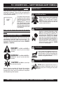
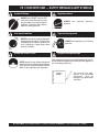
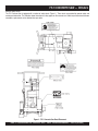
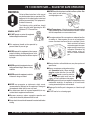
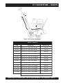
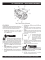
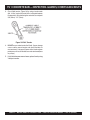
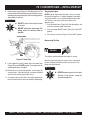
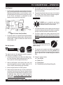
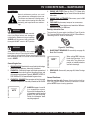
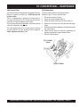
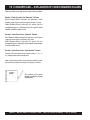
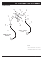
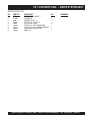
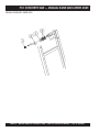
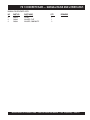
PARTS AND OPERATION MANUAL
CONCRETE SAW
© COPYRIGHT 2003, MULTIQUIP INC.
MODEL FS 1
Revision #3 (04/24/03)
MULTIQUIP INC..
PARTS DEPARTMENT:
18910 WILMINGTON AVE.
800-427-1244
CARSON, CALIFORNIA 90746 FAX: 800-672-7877
310-537-3700
SERVICE DEPARTMENT/TECHNICAL ASSISTANCE:
800-421-1244
800-478-1244
FAX: 310-537-3927
FAX: 310-631-5032
E-mail:[email protected] • www:multiquip.com
Atlanta • Boise • Dallas • Houston • Newark
Montreal, Canada • Manchester, UK
Rio De Janiero, Brazil • Guadalajara, Mexico
PAGE 2 — MQ-WHITEMAN FS1 CONCRETE SAW — PARTS & OPERATION MANUAL — REV. #3 (04/24/03)
HERE'S HOW TO GET HELP
PLEASE HAVE THE MODEL AND SERIAL
NUMBER ON-HAND WHEN CALLING
PARTS DEPARTMENT
800-427-1244 or 310-537-3700
FAX: 800-672-7877 or 310-637-3284
SERVICE DEPARTMENT
800-421-1244
FAX: 310- 537-4259
TECHNICAL ASSISTANCE
800-478-1244
FAX: 310- 631-5032
WARRANTY DEPARTMENT
888-661-4279, or 310-661-4279
FAX: 310- 537-1173
MQ-WHITEMAN FS1 CONCRETE SAW — PARTS & OPERATION MANUAL — REV. #3 (04/24/03) — PAGE 3
TABLE OF CONTENTS
Here's How To Get Help ........................................... 3
Table Of Contents .................................................... 4
Parts Ordering Procedures ...................................... 5
Safety Message Alert Symbols ............................. 6-7
Decals ...................................................................... 8
Rules for Safe Operation .....................................9-11
Dimensions ............................................................ 12
Weights .................................................................. 13
Basic Components ................................................. 14
Basic Engine Components ..................................... 16
General Information ..........................................17-18
MQ-Whiteman — FS 1
Concrete Saw
Inspection Engine .................................................. 19
Inspection Blade .................................................... 20
Inspection Blade Placement ............................. 21-22
Inspection-Guards, Covers, and V-Belts ...........23-24
Initial Start-Up ...................................................25-26
Operation ..........................................................27-28
Maintenance ..................................................... 29-31
Explanation Of Codes In Remarks Column ........... 32
Suggested Spare Parts .......................................... 33
Troubleshooting (Engine) ..................................34-35
Troubleshooting (Blade) ......................................... 36
Under Carriage Assembly .................................38-39
Blade Shaft Assembly .......................................40-41
Frame Assembly ...............................................42-43
Cover Assembly ................................................44-45
Blade Guard Assembly .....................................46-47
Water System Assembly ...................................48-49
Manual Raise and Lower Assembly .................50-51
NOTE
Specification and part
number are subject to
change without notice.
Pointers and Covers Assembly .........................42-43
Cab Assembly ...................................................34-35
Frame, Wheel, Tire and Hub Assembly ............36-37
Name Plate and Decals ....................................38-39
Pi Assembly.......................................................30-31
Name Plate And Decals ....................................32-33
Engines
Engine Assemblies ............................................52-53
Terms and Conditions Of Sale — Parts ................. 54
PAGE 4 — MQ-WHITEMAN FS1 CONCRETE SAW — PARTS & OPERATION MANUAL — REV. #3 (04/24/03)
PARTS ORDERING PROCEDURES
When ordering parts,
please supply the following information:
❒
❒
❒
❒
❒
❒
❒
Dealer account number
Dealer name and address
Shipping address (if different than billing address)
Return fax number
Applicable model number
Quantity, part number and description of each part
Specify preferred method of shipment:
Note: Unless otherwise indicated by customer, all
✓ FedEx or UPS Ground
orders are treated as “Standard Orders”, and will
✓ FedEx or UPS Second Day or Third Day
ship within 24 hours. We will make every effort to
✓ FedEx or UPS Next Day
ship “Air Shipments” the same day that the order is
✓ Federal Express Priority One
received, if prior to 2PM west coast time. “Stock
Orders” must be so noted on fax or web forms.
✓ DHL
✓ Truck
Here’s how to get help...
Please have the model and serial number on
hand when calling.
Parts Department
800-427-1244
310-537-3700
Fax: 800-672-7877
Fax: 310-637-3284
Mayco Parts
800-306-2926
310-537-3700
Fax: 800-672-7877
Fax: 310-637-3284
Service Department
800-478-1244
310-537-3700
Fax: 310-537-4259
MQ Power Service Department
800-835-2551
Fax: 310-638-8046
310-537-3700
Warranty Department
800-421-1244, Ext. 279
310-537-3700, Ext. 279
Fax: 310-537-1173
Multiquip’s Main Phone Numbers
800-421-1244
Fax: 310-537-3927
310-537-3700
MULTIQUIP INC.
18910 WILMINGTON AVENUE
POST OFFICE BOX 6254
CARSON, CALIFORNIA 90749
310-537-3700 • 800-421-1244
FAX: 310-537-3927
E-MAIL: [email protected]
WWW: multiquip.com
Place Your Parts Order Via Web or Fax
For Even More Savings!
Extra Discounts!
All parts orders which include complete part numbers
and are received by our automated web parts order
system, or by fax qualify for the following extra
discounts:
Ordered
via
Fax
Standard
orders
3%
Web
5%
Stock orders
($750 list and above)
10%
10%
Special freight allowances
when you order 10 or more
line items via Web or Fax!**
FedEx Ground Service at no charge for freight
No other allowances on freight shipped by any other
carrier.
NOTE: DISCOUNTS ARE SUBJECT TO CHANGE
Direct TOLL-FREE access
to our Parts Department:
Toll-free nationwide — 800-427-1244
MQ-WHITEMAN FS1 CONCRETE SAW — PARTS & OPERATION MANUAL — REV. #3 (04/24/03) — PAGE 5
FS 1 CONCRETE SAW — SAFETY MESSAGE ALERT SYMBOLS
FOR YOUR SAFETY AND THE SAFETY OF OTHERS!
Safety precautions should be followed at all times when
operating this equipment. Failure to read and understand the
Safety Messages and Operating Instructions could result in
injury to yourself and others.
NOTE
This Owner's Manual has been
developed to provide complete
instructions for the safe and
efficient operations of the
MQWhiteman FS 1 Concrete
Saw. Depending on the power
plant you have selected, please
refer to the engine manufacturers
instructions for data relative to its
safe operations.
Before using this Concrete Saw, ensure that the operating
individual has read and understands all instructions in this
manual.
SAFETY MESSAGE ALERT SYMBOLS
The three (3) Safety Messages shown below will inform you
about potential hazards that could injure you or others. The
Safety Messages specifically address the level of exposure to
the operator, and are preceded by one of three words: DANGER,
WARNING, or CAUTION.
DANGER:
You WILL be KILLED or
SERIOUSLY injured if you do not follow
directions.
WARNING:
You CAN be KILLED or
SERIOUSLY injured if you do not follow
directions.
HAZARD SYMBOLS
Lethal Exhaust Gases
Engine exhaust gases contain poisonous
carbon monoxide. This gas is colorless and
odorless, and can cause death if inhaled.
NEVER operate this equipment in a confined
area or enclosed structure that does not
provide ample free flow air.
Explosive Fuel
Gasoline is extremely flammable, and its
vapors can cause an explosion if ignited. DO
NOT start the engine near spilled fuel or
combustible fluids. DO NOT fill the fuel tank
while the engine is running or hot. DO NOT
overfill tank, since spilled fuel could ignite if it
comes into contact with hot engine parts or
sparks from the ignition system. Store fuel in
approved containers, in well-ventilated areas
and away from sparks and flames. NEVER
use fuel as a cleaning agent.
Burn Hazards
Engine components can generate extreme heat.
To prevent burns, DO NOT touch these areas
while the engine is running or immediately after
operations. Never operate the engine with heat
shields or heat guards removed.
Rotating Parts
CAUTION:
You CAN be injured if you
do not follow directions.
Potential hazards associated with Concrete Saw operations
will be referenced with Hazard Symbols which appear
throughout this manual, and will be referenced in conjunction
with Safety Message Alert Symbols.
NEVER operate equipment with covers, or
guards removed. Keep fingers, hands, hair and
clothing away from all moving parts to prevent
injury.
PAGE 6 — MQ-WHITEMAN FS1 CONCRETE SAW — PARTS & OPERATION MANUAL — REV. #3 (04/24/03)
FS 1 CONCRETE SAW — SAFETY MESSAGE ALERT SYMBOLS
Accidental Starting
Respiratory Hazard
ALWAYS place ON/OFF switch to OFF,
remove key and/or disconnect the spark
plug lead before servicing the engine or
equipment. Ground the lead to prevent
sparks that could ignite a fire.
Over Speed Conditions
ALWAYS wear approved respiratory
protection.
Sight and Hearing hazard
NEVER tamper with the factory settings of the
engine governor or settings. Personal injury
and damage to the engine or equipment can
result if operating in speed ranges above
maximum allowable.
Guards and Covers In Place
NEVER operate the saw without blade guards
and covers in place. Adhere to safety guidelines
ANSI American National Standards Institute,
OSHA or other applicable local regulations.
ALWAYS wear approved eye and hearing
protection.
Equipment Damage Messages
Other important messages are provided throughout this manual
to help prevent damage to your concrete saw, other property, or
the surrounding environment.
NOTE
This concrete saw, other
property, or the surrounding
environment could be
damaged if you do not follow
instructions.
MQ-WHITEMAN FS1 CONCRETE SAW — PARTS & OPERATION MANUAL — REV. #3 (04/24/03) — PAGE 7
FS 1 CONCRETE SAW — DECALS
Machine Safety Decals
The FS 1 Concrete Saw is equipped with a number of safety decals (Figure 1). These decals are provided for operator safety and
maintenance information. The illustration shows these decals as they appear on the concrete saw. Should any of these decals become
unreadable, replacements can be obtained from you dealer.
Figure 1. FS 1 Concrete Saw Decal Placement
PAGE 8 — MQ-WHITEMAN FS1 CONCRETE SAW — PARTS & OPERATION MANUAL — REV. #3 (04/24/03)
FS 1 CONCRETE SAW — RULES FOR SAFE OPERATION
WARNING:
Failure to follow instructions in this manual
may lead to serious injury or even death! This
equipment is to be operated by trained and
qualified personnel only! This equipment is
for industrial use only.
The following safety guidelines should
always be used when operating the MQ
Whiteman FS 1 Concrete Saw:
GENERAL SAFETY
■ DO NOT operate or service this equipment
before reading this entire manual.
■ This equipment should not be operated by
persons under 18 years of age.
■ NEVER operate this equipment without proper
protective clothing, shatterproof glasses, steeltoed boots and other protective devices required
by the job.
■ NEVER operate this equipment when not
feeling well due to fatigue, illness or taking
medicine.
■ NEVER operate this equipment under the
influence or drugs or alcohol.
■ NEVER use accessories or attachments, which are not
recommended by Multiquip for this equipment. Damage to
the equipment and/or injury to user may result.
■ The manufacturer does not assume responsibility for any
accident due to equipment modifications.
■ NEVER touch the hot exhaust manifold, muffler or cylinder. Allow
these parts to cool before
servicing engine or saw.
■ High Temperatures – Allow the engine to cool before adding
fuel or performing service and maintenance functions. Contact
with hot components can cause serious burns.
■ The engine section of this saw requires an adequate free flow
of cooling air. Never operate the saw in any enclosed or
narrow area where free flow of the air is restricted. If the air
flow is restricted it will cause
serious damage to the saw or
engine and may cause injury
to people. Remember the
saw's engine gives off
DEADLY carbon monoxide
gas.
■ Always refuel in a well-ventilated area, away from sparks and
open flames.
■ Always use extreme caution when working
with flammable liquids. When refueling,
stop the engine and allow it to cool. DO
NOT smoke around or near the machine.
Fire or explosion could result from fuel
vapors, or if fuel is spilled on a hot engine.
■ NEVER operate the saw in an explosive atmosphere or near
combustible materials. An explosion or fire could result
causing severe bodily harm or even death.
■ Topping-off to the filler port is dangerous, as it tends to spill
fuel.
■ NEVER use fuel as a cleaning agent.
■ Whenever necessary, replace nameplate, operation and
safety decals when they become difficult to read.
■ Always check the machine for loosened threads or bolts before
starting.
MQ-WHITEMAN FS1 CONCRETE SAW — PARTS & OPERATION MANUAL — REV. #3 (04/24/03) — PAGE 9
FS 1 CONCRETE SAW — RULES FOR SAFE OPERATION
GENERAL SAFETY
DIAMOND BLADE SAFETY
■ Always read, understand, and follow procedures in Operator’s
Manual before attempting to operate equipment.
■ Use appropriate steel centered diamond blades manufactured
for use on concrete saws.
■ Always be sure the operator is familiar with proper safety
precautions and operating techniques before using the saw.
■ Always inspect diamond blades before each use. The blade
should exhibit no cracks, dings, or flaws in the steel centered
core and/or rim. Center (arbor) hole must be undamaged and
true.
■ Stop the engine when leaving the saw unattended.
■ Block the unit when leaving or when using on a slope.
■ Maintain this equipment in a safe operating condition at all
times.
■ Always stop the engine before servicing, adding fuel and oil.
■ NEVER Run engine without air filter. Severe engine damage
may occur.
■ Always service air cleaner frequently to prevent carburetor
malfunction.
■ Always store equipment properly when it is not being used.
Equipment should be stored in a clean, dry location out of the
reach of children.
■ Examine blade flanges for damage, excessive wear and
cleanliness before mounting blade. Blade should fit snugly on
the shaft and against the inside/outside blade flanges.
■ Ensure that blade is marked with an operating speed greater
than the blade shaft speed of the saw.
■ Only cut the material that is specified by the diamond blade.
Read the specifications of the diamond blade to ensure the proper
tool has been matched to the material being cut.
■ Always keep blade guards in place. Exposure of the diamond
blade must not exceed 180 degrees.
■ NEVER use accessories or attachments, which are not
recommended by Multiquip for this equipment. Damage to
the equipment and/or injury to user may result.
■ Ensure that the diamond blade does not come into contact with
the ground or surface during transportation. DO NOT drop the
diamond blade on ground or surface.
■ NEVER operate this saw in areas that contain combustible material
or fumes. Fire and/or explosions may result from errant sparks
from the equipment.
■ The engine governor is designed to permit maximum engine
speed in a no-load condition. Speeds that exceed this limit may
cause the diamond blade to exceed the maximum safe allowable
speed.
■ Ensure that the blade is mounted for proper operating direction.
WARNING:
SAW TRANSPORTATION SAFETY
■ DO NOT operate this equipment unless
all guards and safety devices are attached
and in place.
■ Use the lifting bail and appropriate lifting equipment to ensure
the safe movement of the saw.
■ DO NOT use the handle bars and/or front pointer as lifting points.
■ NEVER tow the saw behind a vehicle.
■ Caution must be exercised while servicing this equipment.
Rotating and moving parts can cause injury if contacted.
■ Keep all inexperienced and unauthorized people away from
the equipment at all times.
■ Unauthorized equipment modifications will void all warranties.
■ Test the ON/OFF switch before operating. The purpose of the
switch is to shut down the engine.
■ Ensure that both pointer bars are positioned appropriately to
minimize their exposure during transportation.
■ Safeguard against extreme saw attitudes relative to level. Engines
tipped to extreme angles may cause oil to gravitate into the cylinder
head making the engine difficult to start.
■ NEVER transport the saw with the blade mounted.
PAGE 10 — MQ-WHITEMAN FS1 CONCRETE SAW — PARTS & OPERATION MANUAL — REV. #3 (04/24/03)
FS 1 CONCRETE SAW — RULES FOR SAFE OPERATION
Emergencies
■ Always know the location of the nearest fire extinguisher
and first aid kit. Know the location of the nearest telephone.
Also know the phone numbers of the nearest ambulance,
doctor and fire department. This information will be
invaluable in the case of an emergency.
Maintenance Safety
■ NEVER lubricate components or attempt service on a running
machine.
■ Always allow the machine a proper amount of time to cool
before servicing.
■ Keep the machinery in proper running condition.
■ Fix damage to the machine immediately and always replace
broken parts.
■ Dispose of hazardous waste properly. Examples of potentially
hazardous waste are used motor oil, fuel and fuel filters.
■ DO NOT use food or plastic containers to dispose of
hazardous waste.
MQ-WHITEMAN FS1 CONCRETE SAW — PARTS & OPERATION MANUAL — REV. #3 (04/24/03) — PAGE 11
FS 1 CONCRETE SAW — DIMENSIONS
Figure 2. FS 1 Concrete Saw Dimensions
TABLE 1. DIMENSIONS
REFERENCE
LETTER
DESCRIPTION
DIMENSION (MM)
A
Max Height (Handle Bars Fully Raised)
50" (1270)
B
Max Height (Handle Bars Fully Lowered)
36" (914)
C
Max Length (Handle Bars Fully Raised & Front Pointer Lowered)
50" (1270)
D
Max Length (Handle Bars Fully Raised & Front Pointer Raised)
39" (991)
E
Max Length (Handle Bars Fully Lowered & Front Pointer Raised)
36." (914)
F
Max Handle Bar Width
26" (660)
G
Max Handle Bar Deflection
16.5" (419)
H
Front Wheel Base
13.5" (343)
I
Rear Wheel Base
16" (406)
J
Max Width
25" (635)
Crated Dimension (L x W x H) 47" (1194) x 30" (762) x 44" (1118)
PAGE 12 — MQ-WHITEMAN FS1 CONCRETE SAW — PARTS & OPERATION MANUAL — REV. #3 (04/24/03)
FS 1 CONCRETE SAW — WEIGHTS
Figure 3. FS 1 Concrete Saw Weights
TABLE 2. WEIGHTS
SAW
DESCRIPTION
WEIGHT (kgs)
FS1-LE14
SAW, FS1, 14", PUSH, LESS ENGINE
160 (73)
FS1-LE18
SAW, FS1, 18", PUSH, LESS ENGINE
165 (75)
FS1-8H14
SAW, FS1, 14", PUSH, 8 HP HONDA
230 (104)
FS1-8H18
SAW, FS1, 18", PUSH, 8 HP HONDA
235 (106)
FS1-8K14
SAW, FS1, 14", PUSH, 8.5 HP KOHLER
230 (104)
FS1-8K18
SAW, FS1, 18", PUSH, 8.5 HP KOHLER
235 (106)
FS1-9H14
SAW, FS1, 14", PUSH, 9 HP HONDA
230 (104)
FS1-9H18
SAW, FS1, 18", PUSH, 9 HP HONDA
235 (106)
FS1-12K14
SAW, FS1, 14", PUSH, 12 HP KOHLER
240 (109)
FS1-12K18
SAW, FS1, 18", PUSH, 12 HP KOHLER
245 (111)
FS1-13H14
SAW, FS1, 14", PUSH, 13 HP HONDA
240 (109)
FS1-13H18
SAW, FS1, 18", PUSH, 13 HP HONDA
245 (111)
Crated Weight (kgs.) 300 lbs (137)
MQ-WHITEMAN FS1 CONCRETE SAW — PARTS & OPERATION MANUAL — REV. #3 (04/24/03) — PAGE 13
FS 1 CONCRETE SAW — BASIC COMPONENTS
BASIC COMPONENTS
Figure 4. FS 1 Concrete Saw Basic Components
PAGE 14 — MQ-WHITEMAN FS1 CONCRETE SAW — PARTS & OPERATION MANUAL — REV. #3 (04/24/03)
FS 1 CONCRETE SAW — BASIC COMPONENTS
BASIC COMPONENTS
NO
DESCRIPTION
PAGE
1
2
3
4
5
6
7
8
UNDER CARRIAGE ASSEMBLY
BLADE SHAFT ASSEMBLY
FRAME ASSEMBLY
BLADE COVER ASSEMBLY
BLADE GUARD ASSEMBLIES
WATER SYSTEM ASSEMBLY
RAISE/LOWER ASSEMBLY
GASOLINE ENGINE ASSEMBLIES
SEE PAGE 38
SEE PAGE 40
SEE PAGE 42
SEE PAGE 44
SEE PAGE 46
SEE PAGE 48
SEE PAGE 50
SEE PAGE 52
MQ-WHITEMAN FS1 CONCRETE SAW — PARTS & OPERATION MANUAL — REV. #3 (04/24/03) — PAGE 15
FS 1 CONCRETE SAW — BASIC ENGINE COMPONENTS
Figure 5. Engine Controls and Components
INITIAL SERVICING
5.
The engine (Figure 5) must be checked for proper lubrication and
filled with fuel prior to operation. Refer to the manufacturers Engine
manual for instructions & details of operation and servicing.
Fuel Valve Lever – OPEN to let fuel flow, CLOSE to stop
the flow of fuel.
6.
Choke Lever – Used in the starting of a cold engine, or in
cold weather conditions. The choke enriches the fuel
mixture.
1.
7.
Air Cleaner – Prevents dirt and other debris from entering
the fuel system. Remove wing-nut on top of air filter
cannister to gain access to filter element.
Fuel Filler Cap – Remove this cap to add unleaded
gasoline to the fuel tank. Make sure cap is tightened
securely. DO NOT over fill.
WARNING
WARNING
NOTE
Operating the engine without
an air filter, with a damaged air
filter, or a filter in need of
replacement will allow dirt to
enter the engine, causing rapid
engine wear.
Adding fuel to the tank should be accomplished only
when the engine is stopped and has had an
opportunity to cool down. In the event of a fuel spill,
DO NOT attempt to start the engine until the fuel residue has been
completely wiped up, and the area surrounding the engine is dry.
8.
Spark Plug – Provides spark to the ignition system. Set
spark plug gap to 0.6 - 0.7 mm (0.028 - 0.031 inch) Clean
spark plug once a week.
2.
Throttle Lever – Used to adjust engine RPM speed (lever
advanced forward SLOW, lever back toward operator
FAST).
9.
Muffler – Used to reduce noise and emissions.
3.
Engine ON/OFF Switch – ON position permits engine
starting, OFF position stops engine operations.
4.
Recoil Starter (pull rope) – Manual-starting method. Pull
the starter grip until resistance is felt, then pull briskly and
smoothly.
WARNING
Engine components can generate extreme heat.
To prevent burns, DO NOT touch these areas
while the engine is running or immediately after operating. NEVER
operate the engine with the muffler removed.
10. Fuel Tank – Holds unleaded gasoline. For additional
information refer to engine owner's manual.
PAGE 16 — MQ-WHITEMAN FS1 CONCRETE SAW — PARTS & OPERATION MANUAL — REV. #3 (04/24/03)
FS 1 CONCRETE SAW — GENERAL INFORMATION
FAMILIARIZATION
POWER PLANTS
The MQWhiteman FS1 Series Concrete Saws are designed for
wet or dry cutting utilizing diamond blades. They have been
engineered for general and industrial flat sawing applications.
The exceptional performance of these saws centers around
simple operating features, top quality components, and committed
attention to state-of-the-art manufacturing. The reinforced heavy
gauge steel frame and chassis assembly has been precisely jig
welded to eliminate operational bending and/or flex that would
lead to diminished blade performance.
The FS1 Saw Series provides a variety of gasoline engine
choices. Selection of a specific engine, and its capacity measured
in horsepower/torque, directly affects the performance of the
diamond blade. The FS1 series is generally classified in the
industry as a "LOW to MEDIUM" horsepower saw.
This classification is particularly useful when selecting the proper
diamond blade for an application. Refer to the engine Owner's
Manual for specific instructions regarding engine operation and
maintenance practices. [See Table 3]
Additionally, the general weight-to-strength ratio design of the
frame and chassis assembly provides for optimum weight
distribution to keep the blade running true in the cut. A rugged
blade shaft bearing assembly ensures minimal flutter and shaft
harmonics providing the most advantageous condition for a
diamond blade at operating speeds.
Heavy-duty front and rear axles, sturdy oversized wheels, and
industrial under carriage assembly ensure accurate tracking and
years of reliable use. A positive locking counter balance Raise/
Lower system with a depth meter easily orients blade elevation.
A hardy water plumbing system evenly distributes optimum water
volume & flow rate to both sides of the blade. Operator control of
the saw is safely accomplished with adjustable ergonomic
handlebars.
All FS1 saws are designed, engineered and manufactured with
strict adherence to American National Standards Institute, Inc.
(ANSI) guidelines B7.1 and B7.5.
TABLE 3. POWER PLANTS
ENGINE MFR.
HP
STARTING SYSTEM
AIR CLEANER
FUEL TANK
GAL. (Liters)
HONDA
8
Manual
Dual Element
1.6 (6.1)
HONDA
9
Manual
Cyclone Air Filtration
1.6 (6.1)
HONDA
13
Manual
Cyclone Air Filtration
1.7 (6.4)
KOHLER
8.5
Manual
Cyclone Air Filtration
1.6 (6.1)
KOHLER
12
Manual
Cyclone Air Filtration
1.8 (6.8)
MQ-WHITEMAN FS1 CONCRETE SAW — PARTS & OPERATION MANUAL — REV. #3 (04/24/03) — PAGE 17
FS 1 CONCRETE SAW — GENERAL INFORMATION
UNDER CARRIAGE SYSTEM
MANUAL RAISE/LOWER SYSTEM
A jig welded heavy steel gauge under carriage chassis assembly
supports the saw in tracking, pivoting and stabilization. Two rear
wheels (8" x 2.0" x 3/4") and two front wheels (4" x 2.0" x 3/4")
supports the chassis. The entire assembly pivots about the rear
carriage and is lubricated through 90-degree grease fitting in
the rear axle tube. [See page 38, Under Carriage Assembly]
A positive locking mechanical raise and lower spring tension
assembly supports elevation cycling operations. A rotating ball
handle permits the engage/disengage process, and the
tension
CCC
spring assists the operator with smooth blade entry and egress.
Blade orientation is referenced on the front face of the handle
bar support tube and is calibrated for 12", 14", 16" and 18"
diamond blades. [See Figure 11 and page 22]
BLADE DRIVE SYSTEM
A rugged blade shaft assembly has been specifically designed
to support the optimum distribution of torque from the engine
shaft to the blade shaft, and to ensure minimal vibratory conditions
on the tips of the shaft. Balanced engine & blade shaft pulleys
are connected to their respective shafts. Two premium V-belts
connect the engine pulley to the blade shaft pulley. The 1-1/4"
diameter blade shaft is supported by two self-aligning pillow
block bearings, and is designed for left and right hand cutting.
[See page 40, Blade Shaft Assembly]
BLADE GUARD ASSEMBLY
The two-piece heavy gauge 14" blade guard is designed with a
water system to meet the challenges of wet cutting operations. A
fluted floodwater manifold assembly supplies optimum volume
and dispersal of water to both sides of the diamond blade for wet
cutting applications. The sizable (6") fluted tubes that direct the
floodwater resist clogging and are easily removed for
maintenance. The blade guard has a convenient "flip-up" front
cover for easy blade changes, and is spring tensioned for positive
up/down positioning. The blade guard may be oriented for left or
right hand cutting.
WATER SYSTEM
The FS1 Series employs a water system that provides floodwater
to the blade. Two 6" fluted tubes are connected via a manifold,
and are oriented inside the blade guard to provide optimum
water volume and dispersal to both sides of the blade. A standard
"garden hose" hookup valve connects the water source to the
saw, and a 2-way water lever (ON/OFF) is conveniently located
for the operator. [See Figure 6 and page 48]
Figure 6. Water Connection/Manual/Raise Lower
Assembly
TABLE 4. BLADE SELECTION
Diamond Blade
Diameter (In.)
Depth of Cut
12"
3 5/8"
14"
4 5/8"
16"
5 5/8"
18"
6 5/8"
PAGE 18 — MQ-WHITEMAN FS1 CONCRETE SAW — PARTS & OPERATION MANUAL — REV. #3 (04/24/03)
FS 1 CONCRETE SAW — INSPECTION -ENGINE
Before Starting
1. Read safety instructions at the beginning of manual.
2. Clean the SAW, removing dirt and dust, particularly the
engine cooling air inlet, carburetor and air cleaner.
3. Check the air filter for dirt and dust. If air filter is dirty, replace
air filter with a new one as required.
4. Check carburetor for external dirt and dust. Clean with dry
compressed air.
Figure 8. Engine Oil Dipstick (Oil Level)
Some engines used with
the FS 1 Concrete Saw
have an oil Alert System.
This
system
will
automatically stop the in
the event of low oil level.
ALWAYS be sure to check
the engine oil level prior to
starting the engine.
5. Check fastening nuts and bolts for tightness.
NOTE
Engine Oil Check
1. To check the engine oil level, place the saw on secure level
ground with the engine stopped, and the diamond blade
removed.
2. Remove the filler cap/dipstick from the engine oil filler hole
(Figure 7) and wipe it clean.
Table 5. Oil Type
Season
Temperature
Oil Type
Summer
25°C or Higher
SAE 10W-30
Spring/Fall
25°C~10°C
SAE 10W-30/20
Winter
0°C or Lower
SAE 10W-10
Figure 7. Engine Oil Dipstick (Removal)
3. Insert and remove the dipstick without screwing it into the filler
neck. Check the oil level shown on the dipstick.
4. If the oil level is low (Figure 8), fill to the edge of the oil filler
hole with the recommended oil type (Table 5). Maximum oil
capacity is 400 cc.
Explosive Fuel
Gasoline Check
1. Remove the gasoline cap located on top of fuel tank.
2. Visually inspect to see if fuel level is low. If fuel is low, replenish
with unleaded fuel.
NOTE
Reference manufacturer
engine manual for specific
servicing instructions.
3. When refueling, be sure to use a strainer for filtration. DO
NOT top-off fuel. Wipe up any spilled fuel.
MQ-WHITEMAN FS1 CONCRETE SAW — PARTS & OPERATION MANUAL — REV. #3 (04/24/03) — PAGE 19
FS 1 CONCRETE SAW — INSPECTION -BLADE
WARNING
Failure to thoroughly inspect the diamond blade (Figure 9) for
operational safety could result in damage to the blade, the saw,
and may cause injury to the user or others in the operating area.
Figure 9. Diamond Blade
1.
Drive Pin Hole – A commonly located hole located on the
diamond blade core that prevents operational blade
slippage between the inner & outer blade flanges (collars).
Inspect the diameter of the hole to ensure there is no
distortion, and that a snug fit develops between the hole
and drive pin.
2.
Stress Relief Holes (Gullets) – Check the steel core for
cracks that may have propagated from the slots and/or
gullets. Cracks indicate extreme fatigue failure and if sawing
continues, catastrophic failure will occur.
3.
Edge Of The Steel Core – Check the diameter edge for
discoloration (blue oxidation) indicating an overheating
condition caused by insufficient cooling water/air.
Overheating of blades may lead to loss of core tension
and/or increase the possibility for blade failure. Check to
make sure the steel core’s width is uniform about the rim of
the blade, and not succumbing to an “under cutting”
condition brought about by highly abrasive material or
improper under cutting core protection.
4.
Directional Arrow – Check to ensure that the blade is
oriented properly on the blade shaft for sawing. Reference
the directional arrow in the blade and place it so the direction
of rotation “downcuts” with the turn of the shaft.
5.
Diamond Segment or Rim – Ensure there are no cracks,
dings, or missing portions of the diamond segment/rim. DO
NOT use a blade that is missing a segment or a portion
of the rim. Damaged and/or missing segments/rims may
cause damage to your saw, and injury to the user or others
in the operating area.
6.
Specifications – Ensure that the blade specifications, size,
and diameter properly match up to the sawing operation.
Wet blades must have water to act as a coolant. Utilizing a
diamond blade not matched properly to the task may result
in poor performance and/or blade damage.
7.
Arbor Hole – It is essential that the arbor hole diameter
properly matches the blade, and that it is free from
distortions. Correct blade flanges (collars) must be used.
The inside face of the flanges must be clean & free of debris.
An out of round arbor condition will cause damage to the
blade and the saw.
8.
MAX RPM – This RPM reference is the maximum safe
operating speed for the blade selected. NEVER exceed
the max RPM on the diamond blade. Exceeding the MAX
RPM is dangerous, and may cause poor performance and
may damage the blade.
PAGE 20 — MQ-WHITEMAN FS1 CONCRETE SAW — PARTS & OPERATION MANUAL — REV. #3 (04/24/03)
FS 1 CONCRETE SAW — INSPECTION -BLADE PLACEMENT
WARNING
4.
Diamond Blade – Ensure that the proper diamond blade
has been selected for the job. Pay close attention to the
directional arrows on the blade, clockwise for right-hand
cutting and counter-clockwise for left-hand cutting, then
place the blade onto the blade shaft, and ensure the arbor
hole of the blade matches the diameter of the shaft.
5.
Blade Drive Pin – Line up the blade drive pin with the
inner flange (collar) pin hole. The blade’s operating
directional arrows must point in a “down-cutting” direction
(whether cutting on right side or left) to perform correctly.
6.
Inner Flange (Collar) – This flange is fixed upon the blade
shaft, and is manufactured with a drive pin hole. The inside
surface of the flange must be free of debris and permit a
tight closure on the surface of the blade.
7.
Blade Shaft Torque Hole – A conveniently placed opening
on the frame that permits the use of the shaft lock wrench to
assist in blade changes. The pointed end of the locking
wrench fits into the saw frame hole and a machined hole in
the blade shaft. Once in place, the blade shaft can not
rotate making it easier to remove the blade nut.
Failure to thoroughly inspect the diamond blade (Figure 10) for
operational safety could result in damage to the blade, the saw,
and may cause injury to the user or others in the operating area.
1.
2.
3.
Blade Guard – Pivot the blade guard front cover all the
way back. The guard tension spring will keep the front cover
in position.
Blade Hex Nut – Unscrew the [blade shaft nut “right hand”
side loosens clockwise, and tightens counter clockwise],
[blade shaft nut “left side” loosens counter clockwise and
tightens clockwise]. Utilize the blade nut wrench and shaft
lock wrench located on the lower inside console cavity.
DO NOT overtighten the nut (approximately 45-50 ft.-lb/
61-68 N/m) when finalizing the assembly.
Outside Blade Flange (Collar) – Ensure that the outside
blade flange is placed flush against the diamond blade,
and that the flange drive pin goes through the blade pin
hole and seats properly into the inner flange drive pin hole.
The inside surface of the flange must be free of debris and
permit a tight closure on the surface of the blade core.
Figure 10. Diamond Blade Placement
MQ-WHITEMAN FS1 CONCRETE SAW — PARTS & OPERATION MANUAL — REV. #3 (04/24/03) — PAGE 21
FS 1 CONCRETE SAW — INSPECTION -BLADE PLACEMENT
NOTE
The following steps should be
accomplished before using
the FS1 on any cutting
surface.
Diamond Blade Placement Procedure
The FS1 is equipped with an Raise/Lower assembly that is
supported by the following components (Figure 11):
■ Raise/Lower Ball Handle (1)
■ Actuating Arm Lever (2)
■ Depth Pointer Bar (3)
■ Raise/Lower Scale (4)
1. Set the engine ON/OFF switch to the OFF
position.
2. Place the FS1 saw on a stable level working surface.
2. Grasp the raise/lower ball handle (1) and reorient the saw
to its highest position by rotating the ball handle counterclockwise while pulling back on the handle bars.
4. Lock this new position in place by maintaining back pressure
on the handle bars while rotating the ball handle clockwise
firmly against the actuating arm lever (2).
5. Lift up the blade guard cover to gain access to the diamond
blade.
NOTE
When removing or installing
a diamond blade, please note
that the blade retaining nuts
are left and right hand
threaded.
6. Use the provided blade nut and blade shaft locking wrenches
(Figure 10) to install the diamond blade. Also reference steps
1 through 7 on page 21.
Figure 11. Raise/Lower Assembly
WARNING
Dropping or forcing the blade onto the cutting surface can
severely damage the diamond blade and may cause serious
damage to the saw and bodily harm.
WARNING
ALWAYS make sure that the ball handle has been securely
locked against the actuating arm lever to prevent blade depth
creep.
7. When cutting, reference the cutting depth by viewing the
depth pointer bar (3) in conjunction with the raise lower scale
until the desired depth is achieved.
8. Always "lock in" the depth by firmly rotating the ball handle
against the actuating arm lever.
PAGE 22 — MQ-WHITEMAN FS1 CONCRETE SAW — PARTS & OPERATION MANUAL — REV. #3 (04/24/03)
FS 1 CONCRETE SAW — INSPECTION -GUARDS, COVERS AND V-BELTS
Guards and Covers Check
V-belts and Cover
CAUTION:
WARNING
NEVER operate the saw without blade guards and covers
(Figures 12,13 and 14) in place. DO NOT operate with the front
of the blade guard raised. The blade exposure cannot exceed
180 degrees during operations. Adhere to the safety guidelines
of the American National Standards Institute (ANSI) B7.1
and B7.5.
NEVER attempt to check the V-belt with the engine running
because severe injury can occur. Keep fingers, hands, hair and
clothing away from all moving parts.
V-belts Alignment and Tensioning
This concrete saw is equipped with two premium V-belts (14")
and three premimum V-belts (18") that have been aligned and
tensioned by factory personnel. All two V-belts MUST be installed
for proper operation of the saw. Failure to run the saw with less
than two belts may damage the saw or equipment.
Use the following procedure to check the alignment of V-belts:
Figure 12. Mist Blade Guard
CHECK the following on the "blade guard":
1. Remove the bolts that secure the V-belt cover (Figure 14) to
the saw frame.
■ Check to ensure the capacity of the blade guard matches the
diameter of your diamond blade.
■ Check that the guard is bolted firmly upon the saw frame.
■ Check that the spring tensioned front cover of the guard is
firmly seated with the rear section of the guard, and there are
no gaps.
■ Check the fit of the water hoses about the water manifold.
NEVER lift the blade guard while cutting.
■ Check that the flood water tubes and water jets are clear and
open. Test the water supply for pressure and flow (to both
sides of the blade) before sawing operations.
CHECK the following on the "blade flange cover":
Figure 14. V-Belt Cover
2. Check uniform parallelism (Figure 15) of V-belts and pulley
(sheaves). Use a straight edge or machinists's square
against both pulleys and adjust both pulleys until equally
aligned.
■ Check that the flange cover seats firmly upon the bayonet
fitting of the saw frame prior to operation.
■ This flange cover is to be in place when cutting from either the
right or left side of the saw.
Figure 13. Blade Flange Cover
Figure 15. Pulley Alignment
MQ-WHITEMAN FS1 CONCRETE SAW — PARTS & OPERATION MANUAL — REV. #3 (04/24/03) — PAGE 23
FS 1 CONCRETE SAW — INSPECTION -GUARDS, COVERS AND V-BELTS
3. Check V-belt tension (Figure 16) by using a tension meter
(6.0 - 9.0 lbs) against the inside belt at a mid point between
the two pulleys, or by deflecting the center belt at a mid point
3/8” (10mm) - 1/2” (13mm).
Figure 16. V-Belt Tension
4. DO NOT over or under tension the V-belts. Severe damage
can occur to the saw and engine crank shaft if the belts are
over tensioned. A decrease of power to the blade and poor
performance will result if the belts are under tensioned (loose
on pulleys).
5. If the V-belts becomes worn or loose, replace them by using
V-belt part number .
PAGE 24 — MQ-WHITEMAN FS1 CONCRETE SAW — PARTS & OPERATION MANUAL — REV. #3 (04/24/03)
FS 1 CONCRETE SAW— INITIAL START-UP
CAUTION:
DO NOT attempt to operate the saw until the
D
Safety, General Information and Inspection
sections have been read and understood.
Depending on engine manufacturer, operating
steps may vary. See engine manufactures
operating manual. The following start-up procedure makes
reference to a HONDA engine.
1. Ensure the diamond blade has been mounted correctly and
that it raised above the surface you about to saw.
The CLOSED position of the
choke lever enriches the fuel
NOTE
mixture for starting a COLD
engine. The OPEN position
provides the correct fuel
mixture for normal operation
after star ting, and for
restarting a warm engine.
5. Place the Choke Lever (Figure 19) in the "OPEN" position
2. Connect to water source (as applicable) see item 7 on page
48 (Water System Assembly), and test for adequate flood
water [ 4 to 5 gallons per minute (15 to 19 LT/min)], and/or
misting water [steady geometric aerosol spray at 40 psi].
3. Place the fuel valve lever (Figure 17) to the "ON" position.
Figure 19. Choke Lever
Figure 17. Fuel Valve Lever
CAUTION:
4. Place the Engine ON/OFF switch (Figure 18) in the "ON"
position.
The engine governor speed has been set at the factory. Changing
the governor speed could damage the blade and/or the saw.
6. Place the throttle lever (Figure 20) halfway between fast
and slow for starting. All sawing is done at full throttle. The
engine governor speed is factory set to ensure optimum
blade operating speeds.
Figure 18. Engine ON/Off Switch
Figure 20. Throttle Lever
MQ-WHITEMAN FS1 CONCRETE SAW — PARTS & OPERATION MANUAL — REV. #3 (04/24/03) — PAGE 25
FS 1 CONCRETE SAW — INITIAL START-UP
8. Grasp the starter grip (Figure 21) and slowly pull it out. The
resistance becomes the hardest at a certain position, corresponding to the compression point. Pull the starter grip briskly
and smoothly for starting.
CAUTION:
z DO NOT pull the starter rope all the way
to the end.
z DO NOT release the starter rope after
pulling. Allow it to rewind as soon as
possible.
Stopping the Engine
NEVER stop the engine while the blade is in the cut, except
for extreme emergencies. A sudden stoppage of the engine
at high speed while in a cut could damage the blade and/or
saw, and may cause injury to the user or other in the
operating area.
1. Place the throttle lever (Figure 20) in the slow position, and
listen for the engine speed to decrease.
2. Place the engine ON/OFF switch (Figure 18) to the “OFF”
position.
3. Place the fuel valve lever (Figure 17) to the “OFF” position.
Maneuvering The Saw
WARNING
The blade is spinning whenever the engine is running.
Figure 21. Starter Grip
9. If the engine has started, slowly return the choke lever
(Figure 19) to the CLOSED position. If the engine has not
started repeat steps 1 through 5.
10. Before the saw is placed into operation, run the engine for
several minutes. Check for fuel leaks, and noises that would
associate with a loose guard and/or covers.
11. All sawing is done at full throttle. Your engine governor has
been set at the factory to ensure an optimum speed setting.
Raise the blade high above the surface when maneuvering
the saw. Damage to the blade and/or saw may occur if the
blade strike the pavement.
CAUTION:
z NEVER stop the engine in the cut while
working at high speeds, except for
extreme emergencies.
PAGE 26 — MQ-WHITEMAN FS1 CONCRETE SAW — PARTS & OPERATION MANUAL — REV. #3 (04/24/03)
FS 1 CONCRETE SAW — OPERATION
Saw Alignment
1. The FS 1 employs a front and rear pointer (Figure 22) that has
been precisely aligned with the diamond blade at the factory.
Referencing the figure below, accurate tracking is accomplished by referencing the front and rear pointer tips over the
cut line. Precise saw direction is accomplished by slight
operator pressure against the handle bars.
5. Set the depth and saw only as the job conditions and
specifications require. Unnecessary deep sawing is wasteful
to the life of your blade.
6. The preferred method of sawing is to step cut in increments
of 2” (51 mm). “Step-cutting” provides the optimum opportunity for the blade to cut fast and last its longest.
CAUTION:
ALWAYS saw in a straight line only. Serious
damage to the blade may occur if the saw is
twisted or forced to cut radius shapes.
7. The rotation of the blade creates a tendency for the saw to pull
in a particular direction (to the right if the blade is mounted on
the right, to the left if the blade is mounted on the left).
Figure 22. Pointer View (Front/Rear)
2. For operator comfort, an ergonomically designed handle bar
adjusts by loosening two clamping knobs and adjusts to the
desired height. Tighten the knobs back down when the
desired height is met.
8. To ensure a straight line of sawing, apply pressure to the
appropriate handle as you slowly advance the saw forward.
DO NOT force the blade to the cut any faster than its natural
tendency.
WARNING
Wet Saw Operation
WARNING
The operator must wear the appropriate protective equipment
and clothing while engaged in sawing.
1. Connect hose from water source to the hose fitting connection (Hose Connection below handle bars) on the saw. The
source pressure should be approximately 40 psi.
2. Select the “ON” position of the two-way water value, and
ensure the proper flow and rate 4-5 gallons/ minute (15-19
Lt/min) is equally directed to both side of the blade.
If the engine stalls for any reason during
sawing, raise the blade out of the cut
before restarting.
9. The operator must recognize and adhere to the optimum
speed that the saw advances while sawing. DO NOT force
the saw in the cut. Observe the engine tachometer from time
to time to get the feel for a smooth sawing pace relative to
RPM.
10. Factors for sawing economy:
z Type of Blade
z Depth of Cut
z Sawing Speed
z Characteristics of the Material Being Cut
3. Advance engine throttle to full (FAST) position.
4. Slowly lower the blade onto your cut line by unlocking the
mechanical Raise/Lower lever (Figure 6); freeing the spring
assisted lowering assembly. Observe the depth of cut with
the depth feed scale, and lock in the depth with the Raise/
Lower handle. IF the water supply to your blade is
interrupted, stop sawing immediately.
MQ-WHITEMAN FS1 CONCRETE SAW — PARTS & OPERATION MANUAL — REV. #3 (04/24/03) — PAGE 27
FS 1 CONCRETE SAW — OPERATION
Dry Saw Operation
WARNING
WARNING
Engine components can
generate extreme heat.
Diamond Blades and Blade Speed
The operator must wear the appropriate protective equipment
and clothing while engaged in sawing.
1. Ensure the proper DRY Cutting blade is selected for the job.
2. The preferred method of sawing is to step cut in increments
of 2” (51 mm). “ Step-cutting” provides the optimum opportunity for the blade to cut fast and last its longest. Airflow acts
as a blade coolant during sawing. Cutting too deep with one
pass, or exerting excessive forward/side-ward pressure may
damage the blade.
1. Diamond Sawing consists of cutting WET or DRY.
2. Matching the correct blade for the specific job and material
being cut optimizes performance and value.
3. Selection of the proper diamond blade consists of:
z Determining WET or DRY cutting
z Material to be Cut
z Type of Saw Being Used
Finishing a Cut
z Horsepower of Saw
1. Raise the blade out of the cut by utilizing the ball handle
adjustment assembly. Raise the blade high enough out of
the cut to clear the surface and allow the saw to be maneuvered.
z Hardness Characteristics of the Material
2. Move the engine throttle lever to the idle (SLOW) position
(Figure 20).
3. Set the engine ON/OFF switch to the “OFF” position
(Figure 18).
4. Place the two-way water valve (Figure 6) in the “OFF”
position .
z Performance Expectations
4. Selecting the “grade” of diamond blade often defines the
performance factors that can be achieved. Multiquip offers a
variety of diamond blade grades to provide the desired level
of valve and performance.
Blade Speed
1. A diamond blade’s performance is directly connected to
specific peripheral (rim) speeds.
2. The following shaft rotational speeds have been factory set
to ensure optimum blade performance.
z FS 1 14” Capacity-3,200 RPM.
z FS 1 18” Capacity-2,700 RPM.
WARNING
Operating saw blades at rotational speeds
greater than those specified by the manufacture can cause blade damage, and may injure the user or others in the operating area.
PAGE 28 — MQ-WHITEMAN FS1 CONCRETE SAW — PARTS & OPERATION MANUAL — REV. #3 (04/24/03)
FS 1 CONCRETE SAW — MAINTENANCE
CAUTION:
General maintenance practices are crucial
to the performance and longevity of your saw.
The extreme environments of sawing operations require routine cleaning, lubrication, belt
tensioning, and inspection for wear and damage
WARNING
The following procedures devoted to maintenance can prevent serious saw damage or
malfunctioning. Before servicing or inspection,
ALWAYS park the saw on a level surface with
the engine ON/OFF switch in “OFF” position.
4. ENGINE AIR FILTER: Clean air filter 2 TO 3 times daily
when DRY cutting. See Engine Owner’s Manual for detailed
information.
5. ENGINE TANK & STRAINER: Clean every year/ or 300
hours.
6. FUEL LINE: Replace every two years/ or as necessary.
7.
SPARK PLUG: Clean/adjust every 6 months/or 100 hours.
Replace every year/ or 300 hours.
Bearing Lubrication Care
There are three (3) grease points (zerk fittings, Figure 23) on the
FS 1 Concrete Saw. Use only Premium Lithium 12 based Grease,
conforming to NLG1 Grade #2 consistency.
Figure 23. Zerk Fitting
WARNING
Some maintenance operations may require
the engine to be run. Ensure that the maintenance area is well ventilated. Exhaust contains poisonous carbon monoxide gas that can cause of unconsciousness and may
result in DEATH
General Engine Care
1. BLADE SHAFT BEARINGS: Grease daily, see page 40,
Blade Shaft Assembly.
NOTE
When cutting DRY, lubricate
blade shaft bearings 2 to 3
times daily. The grease can
provide an added protective
seal for the bearings.
1. ENGINE CHECK: Check daily for any oil and/or fuel leakage,
thread nut & bolt tightness, and overall cleanliness.
2. ENGINE OIL: Check daily. Inspect with blade removed and
saw frame level on a level surface. Keep the oil clean, and
at the proper servicing level (Figure 8). DO NOT OVERFILL!
SAE 10W30 of SG is recommended for general use.
3. ENGINE OIL CHANGE: Change engine oil the first month
or 20 hours of operation. Then every 3 months/ or 50 HOURS
NOTE
2. REAR AXLE: Grease daily, see page 38, Under Carriage
Assembly.
General Cleanliness
Clean the machine daily. Remove all dust and slurry build up.
If the saw is steam cleaned, ensure that lubrication is accomplished AFTER steam cleaning operations.
ALWAYS dispose of used oil
in a responsible manner.
Ensure that the disposition of
all hazardous waste is handled
properly. Call your Recycling
Center for information about
recycling engine oil.
MQ-WHITEMAN FS1 CONCRETE SAW — PARTS & OPERATION MANUAL — REV. #3 (04/24/03) — PAGE 29
FS 1 CONCRETE SAW — MAINTENANCE
Blade Shaft Bearing Replacement
The FS 1 is supported by “tapped" base lock collar self-aligning
blade shaft bearings. These heavy duty bearings support the 11/4 blade shaft, and have grease (zerk) points (Figures 24 and
25) conveniently located for service.
3. To loosen the tension on the two V-belts perform the following:
z Remove the V-belt cover (Figure 14).
z Loosen the engine adjustment bolts (Figure 26).
z Position the engine to allow for slack in the V-belts.
Figure 26. V-Belt Adjustment
Figure 24. Right-Side Shaft Bearing
1. Reference page 40 (Blade Shaft Assembly), during bearing
replacement.
2. Its recommended to replace both left & right hand bearings
collectively.
Replacement of the Blade Shaft Bearings
Perform the following to replace the "blade shaft bearings".
Reference Blade Shaft Assembly drawing, page 40:
4. Remove both the right and left hand blade shaft nuts from
the blade shaft.
5. Remove the blade flanges ( items 3 and 4)
6. Remove pulley set screw (item 8), and slide pulley (item
9 ) off blade shaft.
7. Remove (4) hex head cap screws (item 16) to free the
blade shaft assembly from the saw frame.
8. Remove the set screws from the pillow block bearing,
then slide the bearing(s) off the blade shaft.
9. Position the new blade shaft bearing(s) onto the blade
shaft and ensure that the bearing's zerk fitting is oriented
forward.
10. Re-install blade shaft nuts, pulley and blade shaft flanges
in the reverse order that they were removed.
11. Reposition the V-belts onto the blade shaft pulley, and
realign the V-belts for parallelism (Figure 15) as required.
12. Tighten the V-belts by adjusting the engine adjustment
bolts.
Figure 25. Left-Side Shaft Bearing
13. Replace the V-belt cover guard.
PAGE 30 — MQ-WHITEMAN FS1 CONCRETE SAW — PARTS & OPERATION MANUAL — REV. #3 (04/24/03)
FS 1 CONCRETE SAW — MAINTENANCE
V-Belt Tension Check
Check tension after first day of operation, then weekly/or 25 hours.
Replace as required (see Figure 16). NEVER operate with
less than 2 belts.
The FS 1 is equipped with (2) premium A-27 V-belts for the 14inch model and (3) premimum A-27 V-belts belts for the 18-inch
model which will provide optimum torque transfer.
The saw must be operated with all V-belts, and must be adjusted
collectively and properly to be effective.
The V-belt adjustment of the FS 1 has been factory set utilizing
precision standards. For V-belt adjustments only, see page 23,
V-belts alignment tensioning section.
V-Belt Replacement
To replace V-belts perform the following procedure:
Reference Figure 27 unless otherwise noted.
1.
2.
3.
4.
Remove the belt guard, Figure 14.
Loosen the engine adjustment bolts (1).
Position the engine to allow for slack in the V-belts, (2).
Remove the worn V-belt from the blade shaft and engine
pulleys.
5. Install the new V-belts by looping them around the blade shaft
and engine pulleys.
6. Tighten the new V-belts by collectively repositioning the
engine by tightening the engine adjustment bolts.
7. Re-install the V-belt guard.
FS1 14" Model
Shown
Figure 27. V-Belts
MQ-WHITEMAN FS1 CONCRETE SAW — PARTS & OPERATION MANUAL — REV. #3 (04/24/03) — PAGE 31
FS 1 CONCRETE SAW — TROUBLESHOOTING (ENGINE)
TABLE 6. ENGINE TROUBLESHOOTING
SYMPTON
Difficult to star t, "fuel is available, but no
SPARK at spark plug".
Difficult to star t, "fuel is available, and
SPARK is present at the spark plug".
Difficult to star t, "fuel is available, spark
is present and compression is normal"
Difficult to star t, "fuel is available, spark
is present and compression is low"
No fuel present at carburetor.
POSSIBLE CAUSE
SOLUTION
Spark plug bridging?
Check gap, insulation or
replace spark plug.
Carbon deposit on spark plug?
Clean or replace spark plug.
Shor t circuit due to deficient spark plug
insulation?
Check spark plug insulation,
replace if worn.
Improper spark plug gap?
Set to proper gap.
Engine ON/OFF switch is shor ted?
Check switch wiring, replace
switch.
Ignition coil defective?
Replace ignition coil.
Improper spark gap, points dir try?
Set correct spark gap and
clean points.
Condenser insulation worn or shor t
circuiting?
Replace condenser.
Spark plug wire broken or shor t circuiting?
R e p l a c e d e fe c t i ve s p a r k p l u g
wiring.
Wrong fuel type?
Flush fuel system, and replace
with correct type of fuel.
Water or dust in fuel system?
Flush fuel system.
Air cleaner dir ty?
Clean or replace air cleaner.
Suction/exhaust valve stuck or protruded?
Re-seat valves.
Piston ring and/or cylinder worn?
Replace piston rings and or
piston.
Cylinder head and/or spark plug not
tightened properly?
Torque cylinder head bolts and
spark plug.
Head gasket and/or spark plug gasket
damaged?
Replace head and spar k plug
gaskets.
Fuel not available in fuel tank?
Fill with correct type of fuel.
Fuel cock does not open properly?
Apply lubr icant to loosen fuel
cock lever, replace if necessary.
Fuel filter clogged?
Replace fuel filter.
Fuel tank cap breather hole clogged?
Clean or replace fuel tank cap.
Air in fuel line?
Bleed fuel line.
PAGE 32 — MQ-WHITEMAN FS1 CONCRETE SAW — PARTS & OPERATION MANUAL — REV. #3 (04/24/03)
FS 1 CONCRETE SAW — TROUBLESHOOTING (ENGINE)
TABLE 6. ENGINE TROUBLESHOOTING (CONTINUED)
SYMPTON
"Weak in power" compression is
proper and does not misfire.
POSSIBLE CAUSE
SOLUTION
Air cleaner not clean?
Clean or replace air cleaner
Improper level in carburetor?
Check float adjustment, re-build
carbureator.
Defective Spark plug?
Clean or replace spark plug.
Defective Spark plug?
"Weak in power" compression is
proper but misfires.
Engine overheats.
Rotational speed fluctuates.
Recoil star ter malfunction.
Water in fuel system?
Flush fuel system, and replace
with correct type of fuel.
Dir ty spark plug?
Clean or replace spark plug.
Ignition coil defective?
Replace ignition coil.
Spark plug heat value improper?
Replace with correct type of
spark plug.
Correct type of fuel?
Replace with correct type of fuel
Cooling fins dir ty?
Clean cooling fins.
Governor adjusted correctly?
Adjust governor.
Governor spring defective?
Replace governor spring.
Fuel flow restricted?
C h e c k e n t i r e f u e l s y s t e m fo r
leaks or clogs.
Recoil mechanism clogged with dust and
dir t?
Clean recoil assembly with soap
and water.
Sprial spring loose?
Replace sprial spring.
MQ-WHITEMAN FS1 CONCRETE SAW — PARTS & OPERATION MANUAL — REV. #3 (04/24/03) — PAGE 33
FS 1 CONCRETE SAW — TROUBLESHOOTING (BLADE)
TABLE 7. BLADE TROUBLESHOOTING
SYMPTON
Blade slows or Stops cutting,still
remains on blade.
Blade does not cut straight and/or
true.
Blade discoloring, crackling and/or
wearing excessively.
POSSIBLE CAUSE
SOLUTION
Blade too hard for the material being
cut.
Consult Dealer or Multiquip for correct blade. Try
cutting very soft material (sandstone, silica brick,
cinder block) to "Redress" the blade.
Engine Torgue diminished because of
loose V-Belts.
Tighten and/or replace V-Belts.
Insufficent Engine power.
Check Throttle setting. Check Engine horespower.
Improper direction of rotation.
Check that the blade is oriented, and rotational
arrow points in a "Down-Cutting" direction.
Blade is slipping on the blade shaft.
Check that the blade & flange pin is properly
installed on the blade shaft (see Figure 10).
Blade being used on misaligned saw.
Check blade shaft bearings and alignment
integrity.
Blade is excessively hard for the
material being cut.
Check specifications of the blade with the
material being cut. Consult Dealer or Multiquip for
information.
Blade being used at improper RPM.
Ensure blade surface feet per minute speed
(SFPM) is approximately 10,000 (see Page 29).
Blade improperly mounted on arbor
shoulders and flanges.
Ensure blade is properly affixed on the blade
shaft.
Excessive force applied to blade while
cutting.
Do not force the blade in the cut. Apply a
slow/steady pace to sawing..
Blade too hard for the material being
cut.
Consult Dealer or Multiquip for correct blade. Try
cutting very soft material (sandstone, silica brick,
cinder block) to "Redress" the blade.
Blade improperly mounted on arbor
shoulders and flanges.
Ensure blade is properly affixed on the blade
shaft. Ensure the blade flanges are clean & free
of debris.
Blade not receiving enough cooling
water or air.
Ensure proper flow & volume of water is provided
for wet cutting blades. Ensure sufficent cooling air
is circulated about a dry cutting blade.
Abor hole out of round
Ensure blade is properly affixed on the blade
sh a f t.
Incorrect blade chosen for material
being cut.
Check specifications of the blade with the
material being cut. Consult Dealer or
multiquip for information.
Excessive force applied to blade while
cutting.
Do not force the blade in the cut. Apply a
slow/steady pace to sawing.
PAGE 34 — MQ-WHITEMAN FS1 CONCRETE SAW — PARTS & OPERATION MANUAL — REV. #3 (04/24/03)
FS 1 CONCRETE SAW — NOTE PAGE
MQ-WHITEMAN FS1 CONCRETE SAW — PARTS & OPERATION MANUAL — REV. #3 (04/24/03) — PAGE 35
FS 1 CONCRETE SAW — EXPLANATION OF CODE IN REMARKS COLUMN
How to read the marks and remarks used in this parts book.
Section 1: Items Found In the “Remarks” Column
Serial Numbers-Where indicated, this indicates a serial
number range (inclusive) where a particular part is used.
Model Number-Where indicated, this shows that the
corresponding part is utilized only with this specific model
number or model number variant.
Section 2: Items Found In the “Remarks” Column
Serial Numbers-Where indicated, this indicates a serial number
range (inclusive) where a particular part is used.
Model Number-Where indicated, this shows that the
corresponding part is utilized only with this specific model number
or model number variant.
Section 3: Items Found In the “Items Number” Column
All parts with same symbol in the number column, , #, +, %,
or <, belong to the same assembly or kit.
*
Note: If more than one of the same reference number is listed,
the last one listed indicates newest (or latest) part available.
NOTE
The contents of this parts
catalog are subject to change
without notice.
PAGE 36 — MQ-WHITEMAN FS1 CONCRETE SAW — PARTS & OPERATION MANUAL — REV. #3 (04/24/03)
FS 1 CONCRETE SAW — SUGGESTED SPARE PARTS
FS 1 CONCRETE SAW 1 TO 3 UNITS
1 to 3 Units
Qty. ........ P/N .............................. Description
1 ............ 511329 ........................ SHAFT, BLADE S/N 200003 TO 200009
1 ............ 511659 ........................ SHAFT, BLADE S/N 2000102 ............ 511333 ........................ FLANGE, BLADE INSIDE
1 ............ 511332 ........................ FLANGE, BLADE OUTSIDE
2 ............ 492167 ........................ BEARING PILLOW BLOCK
1 ............ 511331 ........................ NUT, BLADE, RIGHT-HAND
1 ............ 511330 ........................ NUT, BLADE LEFT-HAND
1 ............ 500194 ........................ KEY, 1/4" X 1-3/4
2 ............ 511501 ........................ V-BELT A-27
2 ............ 511433 ........................ WHEELS, REAR
2 ............ 503088 ........................ WHEELS, FRONT
1 ............ 511503F ..................... WRENCH
1 ............ 511502 ........................ TOOL, SHAFT LOCK
Serial number breakdown:
MQ-WHITEMAN FS1 CONCRETE SAW — PARTS & OPERATION MANUAL — REV. #3 (04/24/03) — PAGE 37
FS 1 CONCRETE SAW — UNDER CARRIAGE ASSY.
UNDER CARRIAGE ASSY.
PAGE 38 — MQ-WHITEMAN FS1 CONCRETE SAW — PARTS & OPERATION MANUAL — REV. #3 (04/24/03)
FS 1 CONCRETE SAW — UNDER CARRIAGE ASSY.
UNDER CARRIAGE ASSY.
NO
PART NO
PART NAME
1
2
3
4
5
6
7
8
9
9
10
11
12
13
14
15
16
17
17
18
10024
503078
0730
0948
503602
10024
511471
491704
511407
511661
8151
503111
511487
492586
503088
621
10176
512468
511311
511472
NUT, NYLOC 1/4-20
1
ROD, DEPTH ADJUSTMENT
1
SCREW, HHC 1/4-20 X 1
1
WASHER, FLAT 1/4
2
POINTER, DEPTH
1
NUT, NYLOC 1/2-13
2
TENSIONER, SPRING
1
ZERK FITTING
1
AXLE, REAR .............................................. 1 .................... S/N
AXLE, REAR .............................................. 1 .................... S/N
WASHER, FLAT 3/4
8
SCREW, HHC 1/2-13 X 4-1/4
1
SPRING, DEPTH ADJUSTMENT
1
NUT, NYLOC 5/8 - 11
2
WHEEL, FRONT
2
WASHER, FLAT 1/2
2
NUT, NYLOC 1/2 - 13
1
FRAME, CARRIAGE .................................. 1 .................... S/N
FRAME, CARRIAGE .................................. 1 .................... S/N
PLATE, SPRING ANCHOR
1
QTY.
REMARKS
200003 TO 200009
200010 TO
200003 TO 200009
200010 TO
MQ-WHITEMAN FS1 CONCRETE SAW — PARTS & OPERATION MANUAL — REV. #3 (04/24/03) — PAGE 39
FS 1 CONCRETE SAW — BLADE SHAFT ASSY.
BLADE SHAFT ASSY.
PAGE 40 — MQ-WHITEMAN FS1 CONCRETE SAW — PARTS & OPERATION MANUAL — REV. #3 (04/24/03)
FS 1 CONCRETE SAW — BLADE SHAFT ASSY.
BLADE SHAFT ASSY.
NO
PART NO
PART NAME
1
2
3
4
5
6
7
7
8
9
9
10
11
11
12
13
14
15
16
17
17
511330
503803
511332
511333
511404
492167
511329
511659
492467
505205
512892
500194
511405
512896
511466
511331
504679
10133
490166
511501
511501
NUT, LEFT-HAND
1
PIN, BLADE DRIVE 3/8" X 1"
1
FLANGE, DRIVEN ASSY.
1
FLANGE, BLADE INSIDE
2
BUSHING, LEFT SIDE
1
BEARING, PILLOW BLOCK
2
SHAFT, BLADE ........................................ 1 ............... S/N 200003 TO 200009
SHAFT, BLADE ........................................ 1 ............... S/N 200010 TO
SCREW, SET 5/16" NC X 3/8"
1
PULLEY (2-GROOVE)
1
PULLEY (3-GROOVE) ............................. 1 ............... S/N 20010501
KEY 1/4" X 1-3/4
1
BUSHING, RIGHT SIDE .......................... 1 ............... USED WITH 2-BELT PULLEY
BUSHING, RIGHT SIDE .......................... 1 ............... USED WITH 3-BELT PULLEY S/N20010128
SPACER, BLADE SHAFT
1
NUT, RIGHT-HAND
1
WASHER, FLAT 3/8
8
NUT, NYLOCK 3/8 - 16
4
SCREW, HHC 3/8 - 16 X 3 1/2
4
V-BELT A-27 ............................................. 2 ............... 8.0, 8.5 AND 9.0 HP ENGINES.
V-BELT A-27 ............................................. 3 ............... 11, 12 AND 13 HP ENGINES S/N 20010501
QTY.
REMARKS
MQ-WHITEMAN FS1 CONCRETE SAW — PARTS & OPERATION MANUAL — REV. #3 (04/24/03) — PAGE 41
FS 1 CONCRETE SAW — FRAME ASSY.
FRAME ASSY.
PAGE 42 — MQ-WHITEMAN FS1 CONCRETE SAW — PARTS & OPERATION MANUAL — REV. #3 (04/24/03)
FS 1 CONCRETE SAW — FRAME ASSY.
FRAME ASSY.
NO
PART NO
PART NAME
1
2
3
4
5
6
7
8
9
10
11
12
13
14
15
16
17
18
19
19
20
21
511432
511436
511502
503015
511503F
511481
621
511429
511433
511428
1023
504679
10133
511472
503057
1023
492305
492553
512467
511853
511474
503723
HANDLE, GRIP
2
HANDLE BAR
1
TOOL, SHAFT LOCK
1
KNOB, CLAMPING
2
WRENCH
1
SCREW, WING 5/16-18X1
1
WASHER, FLAT 1/2
2
BUSHING, WHEEL
2
WHEEL, REAR
2
SCREW, ALLEN HEAD 1/2-13X3
2
SCREW, HHC 3/18-16 X 1-1/4
2
WASHER, FLAT 3/8
3
NUT, NYLOC 3/8-16
3
PLATE, SPRING ANCHOR
1
ROD, POINTER
1
SCREW, HHC 3/8-16 X 1-1/4
1
SCREW, HHC 5/16-18 X 1-3/4
2
NUT, HEX FINISH 5/16-18
2
CHASSIS ........................................................ 1 ..................... S/N 200003 TO 200009
CHASSIS ........................................................ 1 ..................... S/N 200010 TO
CLIP, TOOL
1
RIVET
1
QTY.
REMARKS
MQ-WHITEMAN FS1 CONCRETE SAW — PARTS & OPERATION MANUAL — REV. #3 (04/24/03) — PAGE 43
FS 1 CONCRETE SAW — COVER ASSY.
COVER ASSY.
PAGE 44 — MQ-WHITEMAN FS1 CONCRETE SAW — PARTS & OPERATION MANUAL — REV. #3 (04/24/03)
FS 1 CONCRETE SAW — COVER ASSY.
COVER ASSY.
NO
PART NO
PART NAME
1
2
3
4
5
6
7
503012
592623
0655
492597
COVER, BELT
WASHER, LOCK
SCREW, HHC 5/16 - 18 X 3/4
WASHER, FLAT 5/16
503014
503114
COVER, BLADE FLANGE
SCREW, HHC 5/16 - 18 X 3-1/2
QTY.
REMARKS
1
4
2
6
2
1
2
MQ-WHITEMAN FS1 CONCRETE SAW — PARTS & OPERATION MANUAL — REV. #3 (04/24/03) — PAGE 45
FS 1 CONCRETE SAW — BLADE GUARD ASSY.
BLADE GUARD ASSY.
PAGE 46 — MQ-WHITEMAN FS1 CONCRETE SAW — PARTS & OPERATION MANUAL — REV. #3 (04/24/03)
FS 1 CONCRETE SAW — BLADE GUARD ASSY.
BLADE GUARD ASSY.
NO
PART NO
PART NAME
1
2
3
4
5
6
7
8
9
10
11
12
13
14
14
15
16
17
18
19
20
26250
503103
503082
503083
503079
10024
15160
503113
492531
503115
503090
0655
492623
503017
504673
492384
504679
10133
492595
503084
503119
SCREW, HHC 1/4 - 20 X 13/4
FITTING
MANIFOLD
GASKET, MANIFOLD FLOOD
TUBE, FLOOD
NUT, NYLOCK 1/4 - 20 X 3/4
CLIP, CONDUIT
SCREW, COUNTER SUNK 1/4 - 20 X 3/4
NUT, SQUARE 3/16 - 24
SCREW, HHC 3/16 - 24 X 3/4
SPRING, CENTURY
SCREW, HHC 5/16 - 18 X 3/4
WASHER, LOCK 5/16"
GUARD, BLADE 14" BODY
GUARD, BLADE 18" BODY
SCREW, HHC 3/8 - 16 X 4
WASHER, FLAT 3/8
NUT, NYLOC 3/8 - 16
WASHER, FLAT 3/16
FLAP, NEOPRENE WATER SHIELD
NUT, NYLOC 3/16 - 24
QTY.
REMARKS
4
1
1
1
2
6
2
2
4
4
1
4
6
1
1
1
2
1
4
1
2
MQ-WHITEMAN FS1 CONCRETE SAW — PARTS & OPERATION MANUAL — REV. #3 (04/24/03) — PAGE 47
FS 1 CONCRETE SAW — WATER SYSTEM ASSY.
WATER SYSTEM ASSY.
PAGE 48 — MQ-WHITEMAN FS1 CONCRETE SAW — PARTS & OPERATION MANUAL — REV. #3 (04/24/03)
FS 1 CONCRETE SAW — WATER SYSTEM ASSY.
WATER SYSTEM ASSY.
NO
1
2
PART NO
0730
511431
PART NAME
SCREW, HHC 1/4-20 X 1
CLAMP, 3/4
3
4
5
6
7
8
9
0948
491163
10024
491201
503124
491237
503108
WASHER, FLAT 1/4
FITTING, 1/2" X 90" PIPE
NUT, NYLOC 1/4-20
FITTING, 1/2" NPT CONNECTOR
FITTING, 1/2 NPT/ GARDEN HS BRASS
VALVE, BALL COCK 1/2" NPT
HOSE, 1/2
QTY.
4
2
REMARKS
4
2
4
1
1
1
1
MQ-WHITEMAN FS1 CONCRETE SAW — PARTS & OPERATION MANUAL — REV. #3 (04/24/03) — PAGE 49
FS 1 CONCRETE SAW — MANUAL RAISE AND LOWER ASSY.
MANUAL RAISE AND LOWER ASSY.
PAGE 50 — MQ-WHITEMAN FS1 CONCRETE SAW — PARTS & OPERATION MANUAL — REV. #3 (04/24/03)
FS 1 CONCRETE SAW — MANUAL RAISE AND LOWER ASSY.
MANUAL RAISE/LOWER ASSY.
NO
PART NO
PART NAME
1
2
3
4
4910196
503013
503093
503094
KNOB, 3/8 NC
LEVER
WASHER, FLAT
WASHER, COMPOSITE
QTY.
REMARKS
1
1
1
2
MQ-WHITEMAN FS1 CONCRETE SAW — PARTS & OPERATION MANUAL — REV. #3 (04/24/03) — PAGE 51
FS 1 CONCRETE SAW — ENGINE ASSY.
ENGINE ASSY.
PAGE 52 — MQ-WHITEMAN FS1 CONCRETE SAW — PARTS & OPERATION MANUAL — REV. #3 (04/24/03)
FS 1 CONCRETE SAW — ENGINE ASSY.
ENGINE ASSY.
NO
1
1
1
1
1
2
2
3
PART NO
PART NAME
492054
512891
500194
8.0 H.P. HONDA MODEL GX240K1QA2
8.5 H.P. KOLHER MODEL PA-951502
9.0 H.P. HONDA MODEL GX270K1QC9
12.0 H.P. KOHLER MODEL PA-941502
13.0 H.P. HONDA MODEL GX390K1QC9
PULLEY 2-GROOVE
PULLEY 3-GROOVE
KEY, 1/4 X 1- 3/4
QTY.
REMARKS
1
1
1
1
1
1
1
1
MQ-WHITEMAN FS1 CONCRETE SAW — PARTS & OPERATION MANUAL — REV. #3 (04/24/03) — PAGE 53
Effective: October 1, 2002
PAYMENT TERMS
TERMS AND CONDITIONS OF SALE — PARTS
5.
Terms of payment for parts are net 10 days.
FREIGHT POLICY
All parts orders will be shipped collect or
prepaid with the charges added to the invoice.
All shipments are F.O.B. point of origin.
Multiquip’s responsibility ceases when a signed
manifest has been obtained from the carrier,
and any claim for shortage or damage must be
settled between the consignee and the carrier.
MINIMUM ORDER
The minimum charge for orders from Multiquip
is $15.00 net. Customers will be asked for
instructions regarding handling of orders not
meeting this requirement.
RETURNED GOODS POLICY
Return shipments will be accepted and credit
will be allowed, subject to the following provisions:
1.
A Returned Material Authorization must
be approved by Multiquip prior to shipment.
2.
To obtain a Return Material Authorization,
a list must be provided to Multiquip Parts
Sales that defines item numbers, quantities, and descriptions of the items to be
returned.
a. The parts numbers and descriptions
must match the current parts price
list.
b. The list must be typed or computer
generated.
c. The list must state the reason(s) for
the return.
d. The list must reference the sales
order(s) or invoice(s) under which the
items were originally purchased.
e. The list must include the name and
phone number of the person requesting the RMA.
3.
A copy of the Return Material Authorization must accompany the return shipment.
4.
Freight is at the sender’s expense. All
parts must be returned freight prepaid to
Multiquip’s designated receiving point.
6.
Parts must be in new and resalable
condition, in the original Multiquip package (if any), and with Multiquip part
numbers clearly marked.
Rebates for price declines and added charges
for price increases will not be made for stock on
hand at the time of any price change.
b. Any parts with a limited shelf life
(such as gaskets, seals, “O” rings,
and other rubber parts) that were
purchased more than six months
prior to the return date.
for special handling including bus shipments,
insured parcel post or in cases where Multiquip
must personally deliver the parts to the carrier.
Multiquip reserves the right to quote and sell
The following items are not returnable: direct to Government agencies, and to Original
a. Obsolete parts. (If an item is in the Equipment Manufacturer accounts who use our
price book and shows as being products as integral parts of their own products.
replaced by another item, it is SPECIAL EXPEDITING SERVICE
obsolete.)
A $35.00 surcharge will be added to the invoice
LIMITATIONS OF SELLER’S LIABILITY
Multiquip shall not be liable here under for
c. Any line item with an extended dealer damages in excess of the purchase price of the
net price of less than $5.00.
item with respect to which damages are claimed,
d. Special order items.
and in no event shall Multiquip be liable for loss
of profit or good will or for any other special,
e. Electrical components.
consequential or incidental damages.
f. Paint, chemicals, and lubricants.
LIMITATION OF WARRANTIES
g. Decals and paper products.
No warranties, express or implied, are made in
h. Items purchased in kits.
connection with the sale of parts or trade acces7. The sender will be notified of any sories nor as to any engine not manufactured by
material received that is not acceptable. Multiquip. Such warranties made in connection
8. Such material will be held for five with the sale of new, complete units are made
working days from notification, pending exclusively by a statement of warranty
instructions. If a reply is not received packaged with such units, and Multiquip neither
within five days, the material will be assumes not authorizes any person to assume
returned to the sender at his expense. for it any other obligation or liability whatever in
connection with the sale of its products. Apart
9. Credit on returned parts will be issued at from such written statement of warranty, there
dealer net price at time of the original are no warranties, express, implied or statutory,
purchase, less a 15% restocking charge. which extend beyond the description of the
10. In cases where an item is accepted, for products on the face hereof.
which the original purchase document
can not be determined, the price will be
based on the list price that was effective
twelve months prior to the RMA date.
11. Credit issued will be applied to future
purchases only.
PRICING AND REBATES
Prices are subject to change without prior
notice. Price changes are effective on a specific date and all orders received on or after
that date will be billed at the revised price.
PAGE 54 — MQ-WHITEMAN FS1 CONCRETE SAW — PARTS & OPERATION MANUAL — REV. #3 (04/24/03)
NOTE PAGE
MQ-WHITEMAN FS1 CONCRETE SAW — PARTS & OPERATION MANUAL — REV. #3 (04/24/03) — PAGE 55
PARTS AND OPERATION MANUAL
HERE'S HOW TO GET HELP
PLEASE HAVE THE MODEL AND SERIAL NUMBER
ON-HAND WHEN CALLING
PARTS DEPARTMENT
800-427-1244 or 310-537-3700
FAX: 800-672-7877 or 310-637-3284
^^^^^*^^^^^^^^^^^^^^^^^^^^^^^^^*^6668
SERVICE DEPARTMENT/TECHNICAL ASSISTANCE
800-478-1244 or 310-537-3700
FAX: 310- 537-4259
WARRANTY DEPARTMENT
888-661-4279, or 310-661-4279
FAX: 310- 537-1173
MAIN
800-421-1244 or 310-537-3700
FAX: 310-537-3927
MULTIQUIP INC.
POST OFFICE BOX 6254
CARSON, CA 90749
310-537-3700 • 800-421-1244
FAX:310-537-3927
E-MAIL: [email protected]
WWW: multiquip.com
Atlanta • Boise • Dallas • Houston • Newark
Quebec, Canada • Manchester, UK • Rio De Janiero, BR • Guadalajara, MX