1
Owner's Manual
ELECTRIC START
42" MOWER
6 SPEED TRANSAXLE
LAWN TRACTOR
Model No.
917.272073
•
•
•
•
Safety
Assembly
Operation
Maintenance
• Repair Parts
CAUTION:
Read and follow all Safety
Rules and Instructions before
operating this equipment,
For answers to your questions
about this product, Call:
1-800-659-5917
Sears Craftsman Help Line
5 am - 5 pm, Mon- Sat
Sears, Roebuck and Co., Hoffman Estates, II 60179
Visit our Craftsman website:www.sears.com/craftsman
Maintenance
Warranty
...............................................
2
Safety Rules ......................................... 3
Product Specifications .......................... 6
Assembly .............................................. 8
Operation ............................................ 11
Maintenance Schedule ...................... 17
....................................... 17
Service and Adjustments .................... 21
Storage ............................................... 27
Troubleshooting ................................. 28
Repair Parts ........................................ 32
Parts Ordering ..................... Back Cover
LIMITED'I3NO YEAR WARRANTY ON CRAFTSMAN RIDING EQUIPMENT PARTS
For two (2) years from the date of purchase, if this Craftsman Riding Equipment is
maintained, lubricated end tuned up according to the instructions in the owner's
manual, Sears will repair or replace, free of charge, any parts found to be defective in
material or workmanship. Warranty service is available free of charge by taking your
Craftsman riding equipment to your nearest Sears Service Center. In-home warranty
service is available but a trip charge will apply. This warranty applies only while this
product is in the United States.
This Warranty does not cover:
• Expendable items which become worn during normal use, such as blades, spark
plugs, air cleaners, belts and oil filters.
• Tire replacement or repair caused by punctures from outside objects, such as nails,
thorns, stumps, or glass.
• Repairs necessary because of operator abuse, including but not limited to, damage
caused by towing objects beyond the capability of the riding equipment, impacting
objects that bend the frame or crankshaft, or over speeding the engine.
• Repairs necessary because of operator negligence, including but not limited to,
electrical and mechanical damage caused by improper storage, failure to use the
proper grade and amount of engine oil, failure to keep the deck clear of flammable
debris, or the failure to maintain the equipment according to the instructions
contained in the owner's manual.
• Engine (fuel system) cleaning or repairs caused by fuel determined to be contaminated or oxidized (stale). In general, fuel should be used within thirty (30) days of its
purchase date.
• Riding equipment used for commercial or rental purposes.
LIMITED 90 DAY WARRANTY ON BATTERY
For ninety (90) days from date of purchase, if any battery included with this riding
equipment proves defective in material or workmanship and our testing determines
the battery will not hold a charge, Sears will replace the battery at no charge. Warranty service is available free of charge by taking your Craftsman riding equipment to
your nearest Sears Service Center. In-home warranty service is available but a trip
charge will apply. This warranty applies only while this product is in the United States.
TO LOCATE THE NEAREST SEARS SERVICE CENTER OR TO SCHEDULE INHOME WARRANTY SERVICE, SIMPLY CONTACT SEARS AT 1-800-4-MY-HOME
This Warranty gives you specific legal rights, and you may also have other rights
which may vary from state to state.
Sears, Roebuck and Co., D/817 WA, Hoffman Estates, IL 60179
IMPORTANT: This cutting machine is capable of amputating hands and feet and
throwing objects. Failure to observe the following safety instructionscould result in
sedous injury or death.
I, GENERAL OPERATION
II. SLOPE OPERATION
• Read, understand, and follow all
Slopes are a major factor related to lossinstructions in the manual and on the
of-control and tipover accidents, which
machine before starting.
can result in severe injury or death. All
• Only allow responsible adults, who are
slopes require extra caution. If you cannot
familiar with the instructions, to operate
back up the slope or if you feel uneasy on
the machine.
it, do not mow it.
• Clear the area of objects such as
DO:
rocks, toys, wire, etc,, which could be
• Mow up and down slopes, not across.
picked up and thrown by the blade.
• Remove obstacles such as rocks, tree
• Be sure the area is dear of other
limbs, etc.
people before mowing. Stop machine
Watch
for holes, ruts, or bumps.
if anyone enters the area.
Uneven terrain could overturn the
• Never carry passengers.
machine. Ta// grass can hide obstacles.
• Do not mow in reverse unless absoUse slow speed. Choose a low gear so
lutely necessary. Always look down
that you will not have to stop or shift
and behind before and while backing.
while on the slope.
• Be aware of the mower discharge
Follow the manufacturer's recommendirection and do not point it at anyone.
dations for wheel weights or counterDo not operate the mower without
weights to improve stability.
either the entire grass catcher or the
Use extra care with grass catchers or
guard in place.
other attachments. These can change
• Slow down before turning.
the stabilityof the machine.
• Never leave a running machine
Keep all movement on the slopes slow
unattended. Always turn off blades, set
and gradual. Do not make sudden
parking brake, stop engine, and
changes in speed or direction.
remove keys before dismounting,
Avoid starting or stopping on a slope. If
• Turn off blades when not mowing.
tires lose traction, disengage the
• Stop engine before removing grass
blades and proceed slowly straight
catcher or unclogging chute.
down
the slope.
• Mow only in daylight or good artificial
DO NOT:
light.
• Do not turn on slopes unless neces• Do not operate the machine while
sary, and then, turn slowly and graduunder the influence of alcohol or drugs,
ally downhill, if possible.
• Watch for traffic when operating near or
• Do ootmow near drop-offs, ditches, or
crossing roadways.
embankments. The mower could
• Use extra care when loading or
suddenly turn over if a wheel is over the
unloading the machine into a trailer or
truck.
edge of a cliff or ditch, or if an edge
caves in.
• Data indicates that operators, age 60
• Donotmowonwetgrass.
Reduced
years and above, are involved in a
traction could cause sliding.
large percentage of riding mower• Do not try to stabilize the machine by
related injuries. These operators
putting your foot on the ground.
should evaluate their ability to operate
• Donotusegrasscatcheronsteep
the riding mower safely enough to
protect themselves and others from
slopes.
serious injury.
Ill.CHILDREN
Tragic
accidents
canoccurif the operator
is not alert to the presence of children.
Children are often attracted to the
machine and the mowing activity. Never
assume that children will remain where
you last saw them,
• Keep children out of the mowing area
and under the watchful care of another
responsible adult.
• Be alert and turn machine off if children
enter the area.
• Before and when backing, look behind
and down for small children.
• Never carry children, They may fall off
and be seriously injured or interfere
with safe machine operation.
• Never allow children to operate the
machine.
• Use extra care when approaching blind
corners, shrubs, trees, or other objects
that may obscure vision.
IV. SERVICE
• Use extra care in handling gasoline
and other fuels. They are flammable
and vapors are explosive.
-Use only an approved container.
-Never remove gas cap or add fuel
with the engine running. Allow
engine to cool before refueling, Do
not smoke.
-Never refuel the machine indoors.
- Never store the machine or fuel
container inside where there is an
open flame, such as a water heater.
• Never run e machine inside a closed
area.
• Keep nuts and bolts, especially blade
attachment bolts, tight and keep
equipment
in good condition.
• Never tamper with safety devices.
Check their proper operation regularly.
• Keep machine free of grass, leaves, or
other debris build-up. Clean oil or fuel
spillage. Allow machine to cool before
storing.
• Stop and inspect the equipment if you
strike an object. Repair, if necessary,
before restarting.
• Never make adjustments or repairs
with the engine running.
• Grass catcher components ere subject
to wear, damage, and deterioration,
which could expose moving parts or
allow objects to be thrown, Frequently
check components
and replace with
manufacturer's
recommended parts,
when necessary,
• Mower blades are sharp and can cut.
Wrap the blade(s) or wear gloves, and
use extra caution when servicing them.
• Check brake operation frequently.
Adjust and service as required.
• Be sure the area is clear of other
people before mowing. Stop machine if
anyone enters the area.
• Never carry passengers or children
even with the blades off.
• Do not mow in reverse unless absolutely necessary. Always look down
and behind before and while backing.
• Never carry children. They may fall off
and be seriously injured or interfere
with safe machine operation.
• Keep children out of the mowing area
and under the watchful care of another
responsible adult.
4
• Be alert and turn machine off if children
enter the area.
• Before end when backing, look behind
and down for small children.
• Mow up and down slopes (15° Max),
not across.
• Remove obstacles such as rocks, tree
limbs, etc.
• Watch for holes, ruts, or bumps.
Uneven terrain could overturn the
machine. Tall grass can hide obstacles.
• Use slow speed. Choose a low gear so
that you will not have to stop or shift
while on the slope.
• Avoid starting or stopping on a slope. If
tires lose traction, disengage the
blades and proceed slowly straight
down the slope.
• If machine stops while going uphill,
disengage blades, shift into reverse
and back down slowly.
• Do not turn on slopes unless necessary, and then, turn slowly and gradually downhill, if possible.
,_Look for this symbol to point out
important safety precautions. It means
CAUTION!!! BECOMEALERT!!! YOUR
SAFETY IS INVOLVED.
_
CAUTION: In order to prevent
accidental starting when setting up,
transporting, adjusting or making repairs,
always disconnect spark plug wire and
place wire where it cannot contact spark
plug.
_ CAUTION: Do not coast down a hill
in neutral, you may lose control of the
tractor.
_, CAUTION: Tow only the attachments
that are recommended by and comply
with specificationsof the manufacturer of
your tractor. Use common sense when
towing. Operate only at the lowest
possible speed when on a slope. Too
heavy of a load, while on a slope, is
dangerous. Tires can lose traction with
the ground and cause you to lose control
of your tractor.
_.WARNING:
Engine exhaust, some of
its constituents, and certain vehicle
components contain or emit chemicals
known to the State of California to cause
cancer and birth defects or other reproductive harm.
_bWARNING: Battery posts, terminals
and related accessories contain lead and
lead compounds, chemicals known to the
State of California to cause cancer and
birth defects or other reproductive harm.
Wash hands after handling.
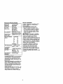
PRODUCT
SPECIFICATIONS
GASOLINE 1.25GALLONS
CAPACITY UNLEADED
ANDTYPE: REGULAR
OILTYPE
SAE10W30
API-SF-SJ):
)IL CAPACITY:
SPARK PLUG:
3AP: .030")
GROUND SPEED
VIPH):
(ABOVE32=F)
SAE 5W-30
(BELOW 32°F)
W/FILTER: 4.5 PINTS
W/OFILTER: 4.0 PINTS
CHAMPION RC12YC
FORWARD:
1sT
1.2
2N°
1.5
3RD
2.4
4 TM
3.5
5 TM
4.8
6 TM
5.3
REVERSE: 1,5
TIRE PRESSURE:
FRONT: 14 PSi
REAR: 10 PSi
CHARGING
SYSTEM:
15 AMPS @ 3600 RPM
BATrERY:
AMP/HR:
30
MIN. CCA: 240
CASE SIZE: UIR
BLADE BOLT
27-35 FT. LBS.
TORQUE:
CONGRATULATIONS on your purchase
of a new tractor. It has been designed,
engineered and manufactured to give
you the best possible dependability and
performance.
Should you experience any problem you
cannot easily remedy, please contact a
Sears or other qualifyed service center.
We have competent, well-trained technicians and the proper tools to service or
repair this tractor.
Please read and retain this manual. The
instructions will enable you to assemble
and maintain your tractor properly.
Always observe the "SAFETY RULES".
REPAIR AGREEMENT
A Repair Agreement is available on this
product. Contact your nearest Sears
store for details.
CUSTOMER RESPONSIBILITIES
• Read and observe the safety rules.
• Follow a regular schedule in maintaining, caring for and using your tractor.
• Follow the instructions under "Maintenance" and "Storage" sections of this
owner's manual.
WARNING: This tractor is equipped
with an internal combustion engine and
should not be used on or near any
unimproved forest-covered, brushcovered or grass-covered land unless the
engine's exhaust system is equipped with
a spark arrester meeting applicable local
or state laws (if any). If a spark arrester is
used, it should be maintained in effective
working order by the operator.
In the state of California the above is
required by law (Section 4442 of the
California Publlc Resources Code).
Other states may have similar laws.
Federal laws apply on federal lands. A
spark arrester for the muffler is available
through your nearest Sears service
center(See REPAIR PARTS section of this
manual).
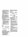
Steering Wheel
Steering
Wheel Insert
(1) Large Flat Washer
1) Lock
washer 3/8
1) Hex Bolt
3/8-16 x 1
(1) Hex Bolt
5/16-18 x 1-1/4
(1)
Locknut
5/16-18
t
j_
Extension
Shaft
teering
Steering
Wheel Adapter
(1) Washer
17/32 x 1-3/16 x 12
Gauge
_(1)
Knob
Slope Sheet
Video Cassette
(2) Keys
Your new tractor has been assembled at the factory with exception of those parts left
unassembled for shipping purposes. To ensure safe and proper operation of your
tractor all parts and hardware you assemble must be tightened securely. Use the
correct tools as necessary to insure proper tightness. Review the video cassette before
you begin.
TOOLS REQUIRED FOR ASSEMBLY
__11nse_
A socket wrench set will make assembly
_!:;
3/8 Hex Bolt
easier. Standard wrench sizes you need
_3/8
Lock Washer
are listed below.
Large Flat
(1) 9/16"wrench
(1) Pliers
Washer
(2) 1/2"wrench
(1) Utility knife
(1) Tire pressure gauge
J
_-_
Steedng Wheel _'_
When right or left hand is mentioned in
this manual, it means, from your point of
view, when you are in the operating
position (seated behind the steering
wheel).
Steering Boot
Tebs
Adapter------'_
TO REMOVE TRACTOR FROM
CARTON
UNPACK CARTON
1. Remove all accessible loose parts
and parts cartons from carton.
2. Cut, from top to bottom, along lines on
all four comers of carton, and lay
panels fiat.
3. Check for any additional loose parts or
cartons and remove.
Shaft
BEFORE REMOVING TRACTOR
FROM SKID
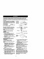
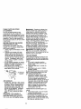
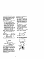
ATTACH STEERINGWHEEL
6. Assemble large fiat washer, 3/8 lock
washer, 3/8 hex bolt and tighten
securely.
7. Snap steering wheel insert into center
of steering wheel.
8, Remove protective materials from
tractor hood and grill.
IMPORTANT: Check for and remove any
staples in skid that may puncture tires
where tractor is to roll off skid.
ASSEMBLE EXTENSION SHAFT AND
BOOT
1. Slide extension shaft onto lower
steering shaft. Align mounting holes
in extension and lower shafts and
install 5/16 hex bolt and Iocknut.
Tighten securely.
2. Place tabs of steering boot over tab
slots in dash and push down to
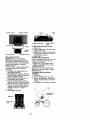
HOW TO SET UP YOUR TRACTOR
CHECK BATTERY
1. Lift seat pan to raised position and
open battery box door.
NOTE: If thisbattery is put into service
after month and year indicated on label
(label located between terminals) charge
battery for minimum of one hour at 6-10
amps. (See "BATTERY" in Maintenance
section of this manual for charging
instructions).
secure.
INSTALL STEERING WHEEL
3. Position front wheels of the tractor so
they are pointing straight forward.
4. Remove steering wheel adapter from
steenng wheel and slide adapter onto
steering shaft extension.
5. Position steering wheel so cross bars
are horizontal (left to right) and slide
inside boot and onto adapter.
8
NOTE: You may now roll or drive your
tractor off the skid. Follow the appropriate
instruction below to remove the tractor
from the skid.
Batter
Door
TO ROLL TRACTOR OFF SKID (See
Operation section for location and
function of controls)
1. Press lift lever plunger and raise
attachment lift lever to its highest
position.
2. Release parking brake by depressing
clutch/brake pedal.
3. Place gearshift lever in neutral (N)
position.
4. Roll tractor forward off skid.
5. Remove banding holding deflector
shield up against tractor.
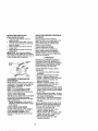
INSTALL SEAT
Adjust seat before tightening adjustment
knob.
1. Remove adjustment knob and fiat
washer securing seat to cardboard
packing and set aside for assembly of
seat to tractor.
2. Pivot seat upward and remove from
the cardboard packing. Remove the
cardboard packing and discard.
3. Place seat on seat pan so head of
shoulder bolt is positioned over large
slotted hole in pan.
4. Push down on seat to engage
shoulder bolt in slot and pull seat
towards rear of tractor.
5. Pivot seat and pan forward and
assemble adjustment knob and flat
washer loosely. Do not tighten.
6. Lower seat into operating position and
sit in seat.
7. Slide seat until a comfortable position
is reached which allows you to press
clutch/brake pedal all the way down.
8. Get off seat without moving its
adjusted position.
9. Raise seat and tighten adjustment
knob securely.
TO DRIVE TRACTOR OFF SKID (See
Operation section for location and
function of controls)
_,WARNING:
Before starting, read,
understand and follow all instructionsin
the Operation section of this manual. Be
sure tractor is in a well-ventilated area. Be
sure the area in front of tractor is clear of
other people and objects.
1. Be sure all the above assembly steps
have been completed.
2. Check engine oil level and fill fuel
tank with gasoline.
3. Sit on seat in operating position,
depress clutch/brake pedal and set
the parking brake.
4. Place gear shift lever in neutral (N)
position.
5. Press lift lever plunger and raise
attachment lift lever to its highest
position.
6. Start the engine. After engine has
started, move throttle control to idle
position.
7. Depress clutch/brake pedal into full
"BRAKE" position and hold. Move
gearshift lever to 1st gear.
8. Slowly release clutch/brake pedal and
slowly dnve tractor off skid.
9. Apply brake to stop tractor, set parking
brake and place gearshift lever in
neutral position.
1O.Tum ignition key to "OFF" position.
Continue with the instructions that follow.
Seat
ar
Bolt
9
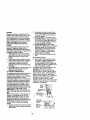
INSTALL MULCHER
PLATE
(If previously removed)
1. Raise and hold deflector shield in
upright position.
2. Place front of mulcher plate over front
of mower deck opening and slide into
place, as shown,
3. Hook front latch into hole on front of
mower deck.
4. Hook rear latch into hole on back of
mower deck.
_CAUTION:
Do not remove deflector
shield from mower. Raise and hold shield
when attaching mulcher plate and allow it
to rest on plate while in operation.
_
Mulcher
Plate
Shield
Latch
Hooks
TO CONVERT TO BAGGING OR
DISCHARGING
Simply remove mulcher plate and store in
a safe place. Your mower is now ready for
discharging or installation of optional
grass catcher accessory.
NOTE: it is not necessary to change
blades. The mulcher blades are designed for discharging and bagging also.
CHECK TIRE PRESSURE
The tires on your tractor were overinflated
at the factory for shipping purposes.
Correct tire pressure is important for best
cutting performance.
• Reduce tire pressure to PSI shown in
"PRODUCT SPECIFICATIONS" section
of this manual.
CHECK DECK LEVELNESS
For best cutting results, mower housing
should be properly leveled. See "TO
LEVEL MOWER HOUSING" in the
Service and Adjustments section of this
manual.
CHECK FOR PROPER POSITION OF
ALL BELTS
See the figures that are shown for
replacing motion and mower blade drive
belts in the Service and Adjustments
section of this manual. Verify that the
belts are routed correctly.
CHECK BRAKE SYSTEM
After you learn how to operate your
tractor, check to see that the brake is
propedy adjusted. See "TO ADJUST
BRAKE" in the Service and Adjustments
section of this manual
/CHECKLIST
BEFORE YOU OPERATEAND ENJOY
YOUR NEW TRACTOR, WE WISH TO
ASSURE THAT YOU RECEIVE THE BEST
PERFORMANCE AND SATISFACTION
FROM THIS QUALITY PRODUCT.
PLEASE REVIEWTHE FOLLOWING
CHECKLIST:
,/All assembly instructionshave been
completed.
,I No remaining loose parts in carton.
,/Battery is properly prepared and
charged. (Minimum 1 hour at 6 amps).
/ Seat is adjusted comfortably and
tightened securely.
/ All tires are properly inflated. (For
shipping purposes, the tires were
overinflated at the factory).
,/Be sure mower deck is properly leveled
side-to-side/front-to-rear for best cutting
results. (Tires must be properly inflated
for leveling).
,/Check mower and drive belts. Be sure
they are routed propedy around pulleys
and inside all belt keepers.
,/Check wiring. See that all connections
are still secure and wires are properly
clamped.
WHILE LEARNING HOW TO USE YOUR
TRACTOR, PAY EXTRAA'I-rENTION TO
THE FOLLOWING IMPORTANT ITEMS:
/ Engine oil is at proper level.
#" Fuel tank is filled with fresh, clean,
regular unleaded gasoline.
/ Become familiar with all controls - their
location and function. Operate them
before you start the engine.
,/Be sure brake system is in safe
operating condition.
10
These symbols may appear on your tractor or in literature supplied with the product,
Learn and understand their meaning.
A,
BATTERY
ENGINE
CAUTION OR
WARNING
ON
ENGINE
REVERSE
OFF
FORWARD
OIL PRESSURE
LIGHTS
FAST
ON
SLOW
!
OVER TEMP
LIGHT
FUEL
CHOKE
MOWER
_r_'l R N
ATTACHMENT
CLUTCH ENGAGED
REVERSE
IGNITION
CLUTCH
NEUTRAL
ATrACHMENT
DANGER,
KEEP HANDS
HEIGHT
pARKING BRAKE
LOCKED
H
L
HIGH
LOW
KEEP AREA
MOWERLI_
®5I
PARKING
SLOPE
BRAKE
HAZARDS
(SEE SAFETY RULES SECTION)
DISENGAGED
AND FEET
CLEAR
UNLOCKED
FREE
AWAY
(Automatic
11
WHEEL
Models
only)
KNOWYOURTRACTOR
READ THIS OWNER'S MANUAL AND SAFETY RULES BEFORE OPERATING
YOUR TRACTOR
Compare the illustrationswith your tractor to familiarize yourself with the locations of
various controls and adjustments. Save this manual for future reference.
Light Switch
Attachment
Ignition Switch
Clutch
Ammeter
/
.....
--.
Lift
Lever
_
Plunger
ThrotUe/Choke
Control
Attachment
Clutch/Brake
Pedal
_ Height
Parking Brake Lever
Gearshift Lever
Our tractors conform to the safety standards of the American
National Standards Institute.
AMMETER - Indicates charging (+) or
discharging (-) of battery.
ATTACHMENT CLUTCH LEVER - Used
to engage the mower blades, or other
attachments mounted to your tractor.
ATTACHMENT LIFT LEVER - Used to
raise, lower, and adjust the mower deck
or other attachments mounted to your
tractor.
CLUTCH/BRAKE PEDAL - Used for
declutching and braking the tractor and
starting the engine.
GEARSHIFT LEVER - Selects the speed
and direction of tractor.
IGNITION SWITCH - Used for starting and
stopping the engine.
LIFT LEVER PLUNGER - Used to release
attachment lift lever when changing its
position.
LIGHT SWITCH - Turns the headlights on
and off.
PARKING BRAKE LEVER - Locks clutch/
brake pedal into the brake position.
THROTTLE/CHOKE CONTROL- Used
for starting and controlling engine speed.
12
The operation of any tractor can result in foreign objects thrown into the
eyes, which can result in severe eye damage. Always wear safety
glasses or eye shields while operating your tractor or performing any
adjustments or repairs. We recommend a wide vision safety mask over
spectacles or standard safety glasses.
HOW TO USE YOUR TRACTOR
TO SET PARKING BRAKE
Your tractor is equipped with an operator
presence sensing switch. When engine
is running, any attempt by the operator to
leave the seat without first setting the
parking brake will shut off the engine.
1. Depress clutch/brake pedal into full
"BRAKE" position and hold.
2. Place parking brake lever in "ENGAGED" position and release
pressure from clutch/brake pedal.
Pedal should remain in =BRAKE"
position, Make sure parking brake will
hold tractor secure,
Attachment Clutch Lever
"Engaged"Position
Throttle/
Ignition Key
Choke
/
Brake
Pedal
Brake
Lever
"BI
Position
Position
STOPPING
MOWER BLADES • To stop mower blades,move attachment clutch lever to "DISENGAGED"
position.
GROUND DRIVE • To stop ground drive, depress clutch/
brake pedal into full "BRAKE" position.
• Move gearshift lever to neutral (N)
position.
ENGINE• Move throttle control to slow position.
NOTE: Failure to move throttle control to
slow position and allowing engine to idle
before stopping may cause engine to
"backfire".
• Turn ignition key to "OFF" position end
remove key. Always remove key when
leaving tractor to prevent unauthorized
IMPORTANT: Leaving the ignition switch
in any position other than "OFF" will
cause the battery to be discharged,
(dead).
NOTE: Under certain conditionswhen
tractor is standing idle with the engine
running, hot engine exhaust gases may
cause "browning"of grass. To eliminate
this possibility,always stop engine when
stopping tractor on grass areas.
_,CAUTION: Always stop tractor
completely, as described above, before
leaving the operator's position;to empty
grass catcher, etc.
TO USE THROTTLE CONTROL
Always operate engine at full throttle.
• Operating engine at less than full
throttle reduces the battery charging
rate.
• Full throttle offers the best bagging and
mower performance.
TO MOVE FORWARD AND BACKWARD
The direction and speed of movement is
controlled by the gearshift lever.
1. Start tractor with clutch/brake pedal
depressed and gearshift lever in
neutral (N) position.
2. Move gearshift lever to desired
position.
3. Slowly release clutch/brake pedal to
start movement.
IMPORTANT: Bring tractor to a complete
stop before shifting or changing gears.
Failure to do so will shorten the useful life
of your transaxle.
TO ADJUST MOWER CUTTING HEIGHT
The position of the attachment lift lever
determines the cutting height.
• Grasp lift lever.
• Press plunger with thumb and move
lever to desired position.
The cutting height range is approximately 1-1/2 to 4". The heights are
measured from the ground to the blade tip
with the engine not running. These
heights are approximate and may vary
depending upon soil conditions, height of
grass and types of grass being mowed.
use.
• Never use choke to stop engine.
13
• The average lawn should be cut to
approximately 2-1/2 inches during the
cool season and to over 3 inches
during hot months. For healthier and
better looking lawns, mow often and
after moderate growth.
• For best cutting performance, grass
over 6 inches in height should be
mowed twice. Make the first cut
relatively high; the second to desired
height.
TO ADJUST GAUGE WHEELS
Gauge wheels are propedy adjusted
when they are slightly off the ground
when mower is at the desired cutting
height in operating position. Gauge
wheels then keep the deck in proper
position to help prevent scalping in most
terrain conditions.
NOTE: Adjust gauge wheels with tractor
on a flat level surface.
1. Adjust mower to desired cutting height
(See =TO ADJUST MOWER CUTTING
HEIGHT" in the Operation section of
this manual).
2. With mower in desired height of cut
position, gauge wheels should be
assembled so they are slightly off the
ground. Install gauge wheel in
appropriate hole with shoulder bolt, 3/
8 washer, and 3/8-16 Ioeknut and
tighten securely.
3. Repeat for opposite side installing
gauge wheel in same adjustment
hole.
Gauge
Wheel
Mounting,_
Bracket - :
o_ _ __
\
Locknut
J)
_"
3/8
Shoulder
"Bolt
Gauge Wheel
TO OPERATE MOWER
Your tractor is equipped with an operator
presence sensing switch. Any attempt by
the operator to leave the seat with the
engine running and the attachment clutch
engaged will shut off the engine.
1. Select desired height of cut.
2, Start mower blades by engaging
attachment clutch control.
TO STOP MOWER BLADES disengage attachment clutch control.
_LCAUTION: Do not operate the mower
without either the entire grass catcher, on
mowers so equipped, or the deflector
shield in place.
Attachment
Clutch Lever
Attachernnt
"Engaged"
igh
Position
. Position
Low
Position
Position
Deflector
Shield
TO OPERATE ON HILLS
_b&.UTION: Do not drive up or down hills
with slopes greater than 15° and do not
drive across any slope.
• Choose the slowest speed before
starting up or down hills,
• Avoid stopping or changing speed on
hills.
• If slowing is necessary, move throttle
control lever to slower position.
• If stopping is absolutely necessary,
push clutch/brake pedal quickly to
brake position and engage parking
brake.
• Move gearshift lever to 1st gear. Be
sure you have allowed room for tractor
to roll slightly as you restart movement.
• To restart movement, slowly release
parking brake and crutch/brake pedal.
• Make all turns slowly.
TO TRANSPORT
• Raise attachment lift to highest position
with attachment lift control,
• When pushing or towing your tractor,
be sure gearshift lever is in neutral (N)
position.
• Do not push or tow tractor at more than
five (5) MPH.
NOTE: To protect hood from damage
when transporting your tractor on a truck
or a trailer, be sure hood is closed and
secured to tractor. Use an appropriate
means of tying hood to tractor (rope, cord,
etc.).
14
TOWING CARTS AND OTHER
ATTACHMENTS
Tow only the attachments that are
recommended by and comply with
specificationsof the manufacturer of your
tractor. Use common sense when towing.
Too heavy of a load, while on a slope, is
dangerous. Tires can lose traction with
the ground and cause you to lose control
of your tractor.
BEFORE STARTING THE ENGINE
CHECK ENGINE OIL LEVEL
The engine in your tractor has been
shipped, from the factory, already filled
with summer weight oil.
1. Check engine oil with tractor on level
ground.
2. Unthread and remove oil fill cap/
dipstick;wipe oil off. Reinsert the
dipstickinto the tube and rest oil fill
cap on the tube. Do not thread the
cap onto the tube. Remove and read
oil level. If necessary, add oil until
"FULL" mark on dipstick is reached.
Do not overfill.
• For cold weather operation you should
change oilfor easier starting(See "OIL
VISCOSITY CHART" in the Maintenance section of this manual).
• To change engine oil, see the Maintenance section in this manual.
ADD GASOLINE
• Fill fuel tank. Use fresh, clean, regular
unleaded gasoline with a minimum of
87 octane. (Use of leaded gasoline
will increase carbon and lead oxide
deposits and reduce valve life). Do
not mix oil with gasoline.
Purchase
fuel in quantities that can be used
within 30 days to assure fuel freshness.
IMPORTANT:
When operating in
temperatures below 32°F(0°C),
use
fresh, clean winter grade gasoline to
help insure good cold weather starting.
_WARNING:
Experience indicates that
alcohol blended fuels (called gasohol or
using ethanol or methanol) can attract
moisture which leads to separation and
formation of acids during storage. Acidic
gas can damage the fuel system of an
engine while in storage. To avoid engine
problems, the fuel system should be
emptied before storage of 30 days or
longer. Drain the gas tank, start the engine
and let it run until the fuel lines and
carburetor are empty. Use fresh fuel next
season. See Storage Instructions for
additional information. Never use engine
or carburetor cleaner products in the fuel
tank or permanent damage may occur.
• I,CAUTION: Fill to bottom of gas tank
filler neck. Do not overfill. Wipe off any
spilled oil or fuel. Do not store, spill or use
gasoline near an open flame.
TO START ENGINE
When startingthe engine for the firsttime or if
the engine has run outoffuel, itwilltake extra
cranking time to move fuel from the tank to the
engine.
1. Sit on seat in operating position,
depress clutch/brake pedal and set
parking brake.
2. Place gear shift lever in neutral (N)
position.
3. Move attachment clutch to "DISENGAGED" position.
4. Move throttle control to choke position.
NOTE: Beforestarting, read the warm and
cold startingprocedures below.
5. Insert key into ignition and turn key
clockwise to "START" position and
release key as soon as engine starts.
Do not run starter continuouslyfor
more than fifteen seconds per minute. If
the engine does not start after several
attempts, move throttle control to fast
position,wait a few minutes and try
again. If engine still does not start,
move the throttle control back to the
choke position and retry.
WARM WEATHER STARTING (50° F and
above)
6. When engine starts, move the throttle
control to the fast position.
• The attachments and ground drive can
now be used. If the engine does not
accept the load, restart the engine and
allow it to warm up for one minute using
the choke as described above.
15
COLD WEATHER STARTING ( 50 ° F and
below)
6. When engine starts, allow engine to
run with the throttle control in the
choke position until the engine runs
roughly, then move throttle control to
fast position. This may require an
engine warm-up period from several
seconds to several minutes, depending on the temperature.
• The attachments can also be used
during the engine warm-up period.
NOTE: If at a highalfitude(above 3000 feet)
or in coldtemperatures(below 32 F) the
carburetorfuel mixturemay need to be
adjustedfor best engine performance. See
"TO ADJUST CARBURETOR" in the Service
and Adjustments se_on of this manual.
MOWING TIPS
• Mower should be properly leveled for
best mowing performance. See "TO
LEVEL MOWER HOUSING" in the
Service and Adjustments section of this
manual.
• The left hand side of mower should be
used for trimming.
• Drive so that clippings are discharged
onto the area that has been cut. Have
the cut area to the right of the tractor.
This will result in a more even distribution of clippings and more uniform
cutting.
• When mowing large areas, start by
turning to the right so that clippings will
discharge away from shrubs, fences,
driveways, etc. After one or two
rounds, mow in the opposite direction
making left hand turns until finished.
• If grass is extremely tall, it should be
mowed twice to reduce load and
possible fire hazard from dried clippings. Make first cut relatively high; the
second to the desired height.
• Do not mow grass when it is wet. Wet
grass will plug mower and leave
undesirable clumps. Allow grass to dry
before mowing.
• Always operate engine at full throttle
when mowing to assure better mowing
performance and proper discharge of
material. Regulate ground speed by
selecting a low enough gear to give the
mower cutting performance as well as
the quality of cut desired.
• When operating attachments, select a
ground speed that will suit the terrain
and give best performance of the
attachment being used.
MULCHING
MOWING TIPS
IMPORTANT: For best performance,
keep mower housing free of built-up
grass and trash. Clean after each use.
• The special mulching blade will recut
the grass clippings many times and
reduce them in size so that as they fall
onto the lawn they will disperse into the
grass and not be noticed. Also, the
mulched grass will biodegrede quickly
to provide nutrients for the lawn.
Always mulch with your highest engine
(blade) speed as this will provide the
best recutting action of the blades.
• Avoid cutting your lawn when it is wet.
Wet grass tends to form clumps and
interferes with the mulching action.
The best time to mow your lawn is the
early afternoon. At this time the grass
has dried and the newly cut area will
not be exposed to the direct sun.
• For best results, adjust the mower
cutting height so that the mower cuts off
only the top one-third of the grass
blades. For extremely heavy mulching,
reduce your width of cut on each pass
and mow slowly.
• Certain types of grass and grass
conditions may require that an area be
mulched a second time to completely
hide the clippings. When doing a
second cut, mow across or perpendicular to the first cut path.
• Change your cutting pattern from week
to week. Mow northto south one week
then change to east to west the next
week. This will help prevent matting
and graining of the lawn.
Max 1/3"
16
1 - Cl_tm_e m,_l o_mt _
operat_g ur_" i heaW k>ad_- In ht,_h mbie_t
GENERAL RECOMMENDATIONS
The warranty on this tractor does not
cover items that have been subjected to
operator abuse or negligence. To receive
full value from the warranty, operator must
maintain tractor as instructed in this
manual.
Some adjustments will need to be made
periodically to properly maintain your
tractor.
All adjustments in the Service and
Adjustments section of this manuel
should be checked at least once each
season.
• Once a year you should replace the
spark plug, clean or replace air filter,
and check blades and belts for wear. A
new spark plug and clean air filter
assure proper air-fuel mixture and help
your engine run better and last longer.
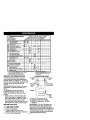
BEFORE EACH USE
1, Check engine oil level.
2, Check brake operation,
3. Check tire pressure,
4. Check operator presence and
interlock systems for proper operation.
5. Check for loose fasteners.
temW_.
5. tr =K;_
v*_h adjw_Z,i lyltom
6. Not r aqelred If e_lpped _
malomnan_ttee baHery
T - l_ghten freer nxka_,o( b._t Io 35 _.4_ maximum
Do eo_ c_e_hte,l
LUBRICATION CHART
Zerk
Zerk
_)Front Wheel,-Bearing
Zerk
=--
Beanng
r -j
=
Zerk
shift
.... _
L__J Pivots
SAE 30 or 10w30 MOTOR OIL
_) GENERALPURPOSE GREASE
(_) REFER TO Maintenance"ENGINE"
SECTION
IMPORTANT: Do not oil or grease the
pivot points which have special nylon
bearings. Viscous lubricantswill attract
dust and dirt that will shorten the life of the
self-lubricating bearings. If you feel they
must belubricated,useonlya dry,powdered
graphitetypelubricantsparingly.
17
TRACTOR
Always observe safety rules when
performing any maintenance.
BRAKE OPERATION
If tractor requires more than six (6) feet
stopping distance at high speed in
highest gear, then brake must be adjusted. (See "TO ADJUST BRAKE" in the
Service and Adjustments section of this
manual).
TIRES
• Maintain proper air pressure in all tires
(See =PRODUCT SPECIFICATIONS"
section of this manual).
• Keep tires free of gasoline, oil, or insect
control chemicals which can harm
rubber.
• Avoid stumps, stones, deep ruts, sharp
objects and other hazards that may
cause tire damage.
NOTE: To seal tire punctures and prevent
fiat tires due to slow leaks, tire sealant
may be purchased from your local parts
dealer. Tire sealant also prevents tire dry
rot and corrosion.
OPERATOR PRESENCE SYSTEM
Be sure operator presence and interlock
systems are working properly. Ifyour
tractor does not function as described,
repair the problem immediately.
• The engine should not start unless the
clutch/breke pedal is fully depressed
and attachment clutch control is in the
disengaged position.
• When the engine is running, any
attempt by the operator to leave the
seat without first setting the parking
brake should shut off the engine.
• When the engine is running and the
attachment clutch is engaged, any
attempt by the operator to leave the
seat should shut off the engine.
• The attachment clutch should never
operate unless the operator is in the
seat.
BLADE CARE
For best results mower blades must be
kept sharp. Replace bent or damaged
blades.
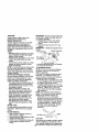
BLADE REMOVAL
1, Raise mower to highest position to
allow access to blades.
2. Remove hex bolt, lock washer and fiat
washer securing blade.
3. Install new or resharpened blade with
trailing edge up towards deck as
shown.
IMPORTANT: To ensure proper assembly,
center hole in blade must align with star
on mandrel assembly.
4. Reassemble hex bolt, lock washer
and flat washer in exact order as
shown.
5. Tighten bolt securely (27-35 Ft. Lbs.
torque).
IMPORTANT: Blade bolt is grade 8 heat
treated.
MandrelAssembly
TrailingEdgeUp
%.
Blade Center
Hole
FlatWasher
Lock Washe
_-Hex
Bolt(Grade *-"_
*A Grade 8 heattreatedboltcan be identified
bysix lines on the bolt head.
TO SHARPEN BLADE
NOTE: We do not recommend sharpening blade - but if you do, be sure the
blade is balanced.
Care should be taken to keep the blade
balanced. An unbalanced blade will
cause excessive vibration and eventual
damage to mower and engine.
• The blade can be sharpened with a file
or on a grinding wheel. Do not attempt
to sharpen while on the mower.
• To check blade balance, you will need
a 5/8" diameter steel bolt, pin, or a cone
balancer. (When using a cone balancer, follow the instructions supplied
with balancer.)
NOTE: Do not use a nail for balancing
blade. The lobes of the center hole may
appear to be centered, but are not.
• Slide blade on to an unthreaded
portion of the steel bolt or pin and hold
the bolt or pin parallel with the ground.
If blade is balanced, it should remain in
a horizontal position. If either end of
the blade moves downward, sharpen
the heavy end until the blade is
balanced.
/" j
//
5/8" Bolt or Pin_"
BATTERY
Your tractor has a battery charging system
which is sufficient for normal use. However, periodic charging of the battery with
18an automotive charger will extend its life.
•
Keep battery and terminals clean.
• Keep battery bolts tight.
• Keep small vent holes open.
• Recharge at 6-10 amperes for 1 hour,
NOTE: The odginal equipment battery on
your tractor is maintenance free. Do not
attempt to open or remove caps or covers.
Adding or checking level of electrolyte is
not necessary.
TO CLEAN BATTERY AND TERMINALS
Corrosion and dirt on the battery and
terminals can cause the battery to "leak"
power.
1. Open battery box door.
2. Disconnect BLACK battery cable first
then RED battery cable and remove
battery from tractor.
3. Rinse the battery with plain water and
dry.
4. Clean terminals and battery cable
ends with wire brush until bright.
5. Coat terminals with grease or petroleum jelly.
6. Reinstall battery (See "REPLACING
BATTERY" in the SERVICE AND
ADJUSTMENTS section of this
manual).
V-BELTS
Check V-belts for deterioration and wear
after 100 hours of operation and replace if
necessary. The belts are not adjustable.
Replace belts if they begin to slip from
wear.
TO CHANGE ENGINE OiL
Determine temperature range expected
before oil change. All oll must meet API
service classification SF-SJ.
• Se sure tractor is on level surface.
• Oil will drain more freely when warm.
• Catch oil in a suitable container.
1. Remove oil fill cap/dipstick. Be careful
not to allow dirt to enter the engine
when changing oil.
2. Remove cap from end of drain valve
and install the drain tube onto the
fitting.
3. Unlock drain valve by pushing inward
slightly and turning counterclockwise.
4. To open, pull out on the drain valve,
5. After oil has drained completely, close
and lock the drain valve by pushing
inward and turning clockwise until the
pin is in the locked position as shown.
6. Remove the drain tube and replace
the cap onto to the end of the drain
valve.
7. Refill engine with oil through oil fill
dipstick tube. Pour slowly. Do not
overfill. For approximate capacity see
"PRODUCT SPECIFICATIONS"
section of this manual.
8. Use gauge on oil fill cap/dipstick for
checking level. Insert dipstick into the
tube and rest the oil fill cap on the
tube. Do not thread the cap onto the
tube when taking reading. Keep oil
at "FULL" line on dipstick. Tighten cap
onto the tube securely when finished.
Oil Drain Valve
TRANSAXLE COOLING
Keep transaxle free from build-up of dirt
and chaff which can restrict cooling.
ENGINE
LUBRICATION
Only use high quality detergent oil rated
with API service classificationSF-SJ.
Select the oil's SAE viscositygrade
according to your expected operating
temperature.
Change the oil after every 50 hours of
operation or at least once a year if the
tractor is not used for 50 hours in one
year,
Check the crankcase oil level before
starting the engine end after each eight
(8) hours of operation. Tighten oil fill cap/
dipstick securely each time you check the
oil level.
Closed
and _]P'_L_",_.-"
Locked I
_.4_/'_-_
Position
_ DrainTube
I /
CLEAN AIR SCREEN
Air screen must be kept free of dirt and
chaff to prevent engine damage from
overheating. Clean with a wire brush or
compressed air to remove dirt end
stubborn dried gum fibers.
CLEAN AIR INTAKE/COOLING AREAS
To insure proper cooling, make sure the
grass screen, cooling fins, and other
external surfaces of the engine are kept
clean at all times,
19
SPARK PLUGS
Replace spark plugs at the beginning of
each mowing season or after every 100
hours of operation, whichever occurs first.
Spark plug type and gap setting are
shown in "PRODUCT SPECIFICATIONS"
section of this manual.
Every 100 hours of operation (more often
under extremely dusty, dirty conditions),
remove the blower housing and other
cooling shrouds. Clean the cooling fins
and external surfaces as necessary.
Make sure the cooling shrouds are
reinstalled.
NOTE: Operating the engine with a
blocked grass screen, dirty or plugged
cooling fins, and/or cooling shrouds
removed will cause engine damage due
to overheating.
AIR FILTER
Your engine will not run properly using a
dirty air filter. Clean the foam pre-cleaner
after every 25 hours of operation or every
season. Service paper cartridge every
100 hours of operation or every season,
whichever occurs first.
Service air cleaner more often under
dusty conditions.
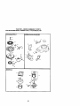
1. Remove knob and cover.
2. Remove wing nut and air cleaner from
base.
ENGINE OIL FILTER
Replace the engine oil filter every season
or every other oil change if the tractor is
used more than 100 hours in one year.
1. Drain oil from engine crankcase (See
"TO CHANGE ENGINE OIL" in this
section of this manual, through step
remove drain plug),
2. Remove oil filter and wipe off filter
adapter.
3. Apply a thin coating of new engine oil
to the rubber gasket on replacement
oil filter.
4. Install replacement oil filter on filter
adapter. Turn oil filter clockwise until
rubber gasket contacts the filter
adapter, then tighten filter an additional 1/2 turn.
5. Fill crankcase with new oil (See "TO
CHANGE ENGINE OIL" in this section
of this manual). For approximate
capacity see "PRODUCT SPECIFICATIONS" section of this manual
6. Start the engine and check for oil
leaks. Correct any leaks before
placing engine into full operation.
TO SERVICE PRE-CLEANER
3. Slide foam pre-cleaner off cartridge.
4. Wash it in liquid detergent and water.
5. Squeeze it dry in a clean cloth. Allow
it to dry.
6. Saturate it in engine oil. Wrap it in
clean, absorbent cloth and squeeze to
remove excess oil.
TO SERVICE CARTRIDGE
• Replace a dirty, bent, or damaged
cartridge.
NOTE: Do not wash the paper cartridge
or use pressurized air, as this will
damage the cartridge.
7. Reinstall the pre-oleaner (cleaned
and oiled) over the paper cartridge.
8. Reassemble air cleaner, wing nut,
cover and tighten knob securely.
PreI
.
Aw Cleaner
Paper Cartndge
MUFFLER
Inspect and replace corroded muffler and
spark arrester (if equipped) as it could
create a fire hazard and/or damage.
IN-LINE FUEL FILTER
The fuel filter should be replaced once
each season. If fuel filter becomes
clogged, obstructing fuel flow to carburetor, replacement is required.
1. With engine cool, remove filter and
plug fuel line sections.
2. Place new fuel filter in position in fuel
line with arrow pointing towards
carburetor.
3. Be sure there are no fuel line leaks
and clamps are properly positioned.
4. Immediately wipe up any spilled
gasoline.
2O
• Keep finished surfaces and wheels free
of all gasoline, oil, etc.
• Protect painted surfaces with automotive type wax.
We do not recommend using a garden
hose to clean your tractor unless the
electdcel system, muffler, air filter and
carburetor are covered to keep water out.
Water in engine can result in a shortened
engine life.
:: : Camp
CLEANING
• Clean engine, battery, seat, finish, etc.
of all foreign matter.
CAUTION: BEFORE PERFORMING ANY SERVICE OR ADJUSTMENTS:
1. Depress clutch/brake pedal fully and set parking brake.
2. Place gearshift lever in neutral (N) position.
3. Place attachment clutch in "DISENGAGED" position.
4. Turn ignitionkey "OFF" and remove key.
5. Make sure the blades and all moving parts have completely stopped.
6. Disconnect spark plug wire from spark plug and place wire where it cannot
come in contact with plug.
TRACTOR
TO REMOVE MOWER
Mower will be easier to remove from the
right side of tractor.
1. Place attachment clutch in "DISENGAGED" position.
2. Move attachment lift lever forward to
lower mower to its lowest position.
3. Roll belt off engine pulley.
4. Remove small retainer spring, and lift
clutch spring off pulley bolt.
5. Remove large retainer spring, slide
collar off and push housing guide out
of bracket.
6. Disconnect anti-swaybar from chassis
bracket by removing retainer spring.
7. Disconnect suspension arms from
rear deck brackets by removing
retainer springs.
8. Disconnect front links from deck by
removing retainer springs.
9. Raise lift lever to raise suspension
arms. Slide mower out from under
tractor.
IMPORTANT: If an attachment other than
the mower deck is to be mounted on the
tractor, remove the front links and hook
the clutch spring Into square hole in
frame.
TO INSTALL MOWER
1. Raise attachment lift lever to its
highest position.
2. Slide mower under tractor with
discharge guard to right side of tractor.
3. Lower lift lever to its lowest position.
4. Install mower in reverse order of
removal instructions.
=.
"" k
Small Retainer Spring
Clutch Spdng_
Suspension Arms
.""
-.4"'-:"
Square Hole
._;._.--Front
Link
Retainer S
Anti-Sway
Springs
(Both Sides)
Collar
Housing Guide
Larg_
21
TO LEVEL MOWER HOUSING
Adjust the mower while tractor is parked
on level ground or driveway. Make sure
tiros are properly inflated (See =PRODUCT SPECIFICATIONS" section of this
manual). If tires aro over or
underinflated, you will not properly adjust
your mower.
SIDE-TO-SIDE ADJUSTMENT
• Raise mower to its highest position.
• At the midpoint of both sides of mower,
measure height from bottom edge of
mower to ground. Distance"A" on
both sides of mower should be the
same or within 1/4" of each other.
• If adjustment is necessary, make
adjustment on one side of mower only.
• To raise one side of mower, tighten lift
link adjustment nut on that side.
• To lower one side of mower, loosen lift
link adjustment nut on that side.
NOTE: Each full turn of adjustment nut
will change mower height about 1/8".
• Recheck measurements after adjusting.
BottomEdgeof
Mowerto Ground
\
Measure distance "D" directly in front and
behind the mandrel at bottom edge of
mower housing as shown.
• Before making any necessary adjustments, check that both front links are
equal in length. Both links should be
approximately 10-3/8".
• If links are not equal in length, adjust
one link to same length as other link.
• To lower front of mower loosen nut "E"
on both front links an equal number of
turns.
• When distance "D" is 1/8" to 1/2" lower
at front than rear, tighten nuts "F"
against trunnion on both front links.
• To raise front of mower, loosen nut "F"
from trunnion on both front links.
Tighten nut "E" on both front links an
equal number of turns.
• When distance "D" is 1/8" to 1/2" lower
at front than rear, tighten nut "F" against
trunnion on both front links.
• Recheck side-to-side adjustment.
BottomEdgeof
Mowerto Ground
/
BOTH FRONT LINKS MUST BE EQUAL
IN LENGTH
Suspension
Arm
-IL
iftLink
'
Adjustment
_--_Nut
FRONT-TO-BACK ADJ USTME NT
IMPORTANT: Deck must be level side-toside.If the following front-to-back adjustment is necessary, be sure to adjust both
front links equally so mower will stay
level side-to-side.
To obtain the best cutting results, the
mower housing should be adjusted so
that the front is approximately 1/8" to 1/2"
lower than the rear when the mower is in
its highest position.
-Nut =E"
Front
Links
22
Trunnion
TO REPLACE MOWER BLADE DRIVE
BELT
The mower blade drive belt may be
replaced without tools. Park the tractor
on level surface. Engage parking brake.
BELT REMOVAL1. Remove mower from tractor (See "TO
REMOVE MOWER" in this section of
this manual).
2. Work belt off both mandrel pulleys
end idler pulleys.
3. Pull belt away from mower.
BELT INSTALLATION 4. Install new belt in reverse order of
removal.
5. Make sure belt is in all pulley grooves
and inside all belt guides.
6. Install mower in reverse order of
removal instructions.
Mandrel
Idler Pulleys
Mandrel
Pulley
TO ADJUST BRAKE
Your tractor is equipped with an adjustable brake system which is mounted on
the right side of the transaxle.
If tractorrequires more than six (6) foot
stopping distance at high speed in highest
gear on a level dry concrete or paved
surface, then brake must be adjusted.
1. Depress clutch/brake pedal and
engage parking brake.
2. Measure distance between brake
operating arm and nut "A" on brake
rod.
3. If distance is other than 1-1/2", loosen
jam nut and turn nut "A"until distance
becomes 1-1/2". Retighten jam nut
against nut "A".
4. Road test tractor for proper stopping
distance as stated above. Readjust if
necessary. If stopping distance is still
greater than six (6) feet in highest
gear, further maintenance is necessan/. Contact a Sears or other
qualified service center.
With Parking Brake "Engaged"
Nut "A"
jl_JOJamNut
I_
perating
Arm
TO REPLACE MOTION DRIVE BELT
Park the tractor on level surface. Engage
parking brake. For assistance, there is a
belt installation guide decal on bottom
side of left footrest.
1. Remove mower (See "TO REMOVE
MOWER" in this section of this
manual.)
2. Remove belt from stationary idler and
clutching idler.
3. Pull belt slack toward rear of tractor.
Remove belt upwards from transaxle
pulley by deflecting belt keepers.
4. Pull belt toward front of tractor and
remove downwards from around
engine pulley.
5. Install new belt by reversing above
procedure.
PulleyClutching-.---_
Idler
Stationary-"
Idler
mransaxle,
Engine
23
TRANSAXLE GEAR SHIFT LEVER
NEUTRAL ADJUSTMENT
The transaxle should be in neutral when
the gear shift ]ever is in neutral (N) (lock
gate) position.The adjustment is preset at
the factory; however, if adjustment is
needed, proceed as follows:
1. Make sure transaxle is in neutral (N).
NOTE: When the tractor rear wheels
move freely, the transaxle is in neutral.
2. Loosen adjustment bolt in front of the
right rear wheel.
3. Position the gear shift lever in the
neutral (N) position.
4. Tighten adjustment bolt securely.
NOTE: If additional clearance is needed
to get to adjustment bolt, move mower
deck height to the lowest position.
Gearshift Lever
Neutral Lock Gate
Adjustment Bolt
TO ADJUST STEERING WHEEL ALIGNMENT
If steering wheel crossbars are not
horizontal (left to right) when wheels are
positioned straight forward, remove
steering wheel and reassemble per
instructionsin the Assembly section of
this manual.
FRONT WHEEL TOE-IN/CAMBER
The front wheel toe-in and camber are
not adjustable on your tractor. If damage
has occurred to affect the front wheel toein or camber, contact a Sears or other
qualified service center.
TO REMOVE WHEEL FOR REPAIRS
1. Block up axle securely.
2. Remove axle cover, retaining ring and
washers to allow wheel removal (rear
wheel contains a square key - Do not
lose).
3. Repair tire and reassemble.
NOTE: On rear wheels only: align
grooves in rear wheel hub and axle.
Insert square key.
4. Replace washers and snap retaining
ring securely in axle groove.
5. Replace axle cover.
NOTE: To seal tire punctures and prevent
fiat tires due to slow leaks, tire sealant
may be purchased from your local parts
dealer. _re sealant also prevents tire dry
rot and corrosion.
Retaining_
Ring
Axle
Washers
i
Square Key _
(RearWheel Only)
TO START ENGINE WITH A WEAK
BATTERY
_CAUTION:
Lead-acid batteries
generate explosive gases. Keep sparks,
flame and smoking materials away from
batteries. Always wear eye protection
when around batteries.
If your batlery is too weak to start the
engine, it should be recharged. (See
"BATTERY* in the MAINTENANCE
section of this manual).
If "jumper cables" are used for emergency
starting, follow this procedure:
IMPORTANT: Your tractor is equipped
with a 12 volt negative grounded system.
The other vehical must also be a 12 volt
negative grounded system. Do not use
your tractor battery to start other vehicles.
TO ATTACH JUMPER CABLES 1. Connect each end of the RED cable to
the POSITIVE (+) terminal of each
battery, taking care not to short
against chassis.
2. Connect one end of the BLACK cable
to the NEGATIVE (-) terminal of fully
charged battery.
3. Connect the other end of the BLACK
cable to good CHASSIS GROUND,
away from fuel tank and battery.
TO REMOVE CABLES, REVERSE ORDER1. BLACK cable first from chassis and
then from the fully charged battery.
2. RED cable last from both batteries.
24
Positive Terminal
Negative Terminal
Keps_
Hex
Nut -">0
Bolt
Positive (Red) Cable
TO REPLACE HEADLIGHT BULB
1. Raise hood.
2. Pull bulb holder out of the hole in the
backside of the grill.
3. Replace bulb in holder and push bulb
holder securely back into the hole in
the backside of the grill.
4. Close hood.
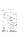
INTERLOCKS AND RELAYS
Loose or damaged wiring may cause your
tractor to run poorly, stop running, or
prevent it from starting.
• Check wiring. See electrical wiring
diagram in the Repair Parts section.
TO REPLACE FUSE
Replace with 20 amp automotive-type
plug-infuse. The fuse holder is located
behind the dash.
TO REMOVE HOOD AND GRILL
ASSEMBLY
1. Raise hood.
2. Unsnap headlight wire connector.
3. Stand in front of tractor. Grasp hood
at sides, tilt toward engine and lift off
of tractor.
4. To replace, reverse above procedure.
Charged
Battery
Positive Terminal
Negative (Black)
Cable
Negative Terminal
REPLACING BATTERY
_CAUTION:
Do not short battery
terminals by allowing a wrench or any
other object to contact both terminals at
the same time. Before connecting battery,
remove metal bracelets, wristwatch
bands, rings, etc.
Positive terminal must be connected first
to prevent sparking from accidental
grounding.
1. Lift seat pan to raised position and
open battery box door.
2. Disconnect BLACK battery cable first
then RED battery cable and carefully
remove battery from tractor.
3. Install new battery with terminals in
same position as old battery.
4. First connect RED battery cable to
positive (+) terminal with hex bolt and
keps nut as shown. Tighten securely.
5. Connect BLACK grounding cable to
negative (-) terminal with remaining
hex bolt and keps nut. Tighten
securely.
6. Close battery box door.
f
- \
\_ \
Hood
HeadlightWire
Connector
Battery
Door
25
ENGINE
Maintenance,repair,or replacementof the
emissioncentJ_ devicesand systems,which
are beingdone at the customersexpense,
may be pedonnedby any non-roadengine
repairestabiishrnentor individual.Warranty
repairsmust be performedby an authorized
enginemanufacturer'sservice outfat.
TO ADJUST THROTTLE CONTROL
CABLE
The throttle controlhas been presetat the
factory end adjustmentshouldnot be
necessary.Check adjustmentas described
belowbefore looseningcable. If adjustmentis
necessary,proceed as follows:
1. Withengine notrunning,move throttle
controlleverfrom slow to choke position.
Slowlymove lever from choke to fast
position.
2. Check to see if holein throttle lever and
hole in speed controlbracketare aligned.
3. if holes are notaligned,loosencable
clamp screw and alignthe holes by
insertinga pencilor a 1/4" drillbitthrough
bothholes.
4. Pullthrottle cableup to remove slackand
tightencable clamp screw. Remove
alignmentpencilor ddllbit.
TO ADJUST CARBURETOR
The carburetorhas been presetat the factory
and adjustmentshouldnot be necessary.
However,minor adjustmentmay be required
to compensatefor differencesin fuel,
temperature, altitude or load. If the carburetor
does need adjustment, proceed as follows:
In general, fuming the adjus_ng needles in
(clockwise) decreases the supply of fuel to
the engine gMng a leaner fuel/air mixture.
Tuming the adjusting needles out (ccJJnterdockwise) increases the supply of fuel to the
engine giving a rk;herfuel/air mixture.
IMPORTANT: Damage to the needles and
seats in carburetor may resultif turned in too
tight.
NOTE: The cerburetor on this engine is low
emissk)n. It is equipped with an idle fuel
adju_ng needle with a ]imiter cap, which
allows some adjustment within the limits
allowed by the cap. Do not attempt to remove
the limitercap. The limJtercap cannot be
removed without breaking the adjusting
needle.
1. Be sure you have a dean air filterand the
throttle controlcable is adjusted properly
(see above).
2. Start engineand allow to warm for five
minutes. Make adjustmentswith engine
running and shifVmofien control lever in
neutral (N) pesitJon.
3. Idle seeed settina- With throttle control
lever in slow position,engine shouldidle
at 1750 RPM. if engineidlestoo slowor
fast, turnidle speed adjustingscrew in or
outunitlcorre_ idle is attained.
4. Idlefuel needlesetting- W_ throttle
controllever in slow pesitJon,turnidlefuel
adjustment needle in (clockwise) until
engine begins to die and then rum out
(counterclockwise) until engine runs
rough. Tum needle to a point midway
between those two positions.
5. Recheck idle speed. Readjust if necessery.
ACCELERATION TEST 6. Move throttle control lever from slow to
fast pasltJon,if engine hesitates or dies,
turn idle fuel adjusting needle out
(counterclockwise) 1/8 tam. Repeat test
and cenitnue to adjust, if necessary, until
engine accelerates smoothly.
High speed stop is factory adjusted. Do
not adjust - damage may result.
IMPORTANT: Never tamper with the
engine governor, which is factory set for
proper engine speed. Overspeeding the
engine above the factory high speed
setting can be dangerous. If you think the
engine-governed high speed needs
adjusting, contact a Sears or other
qualified service center, which has proper
equipment and experience to make any
necessary adjustments.
Cable
Clamp _
Screw
Speed Control
Bracket
_ver
Adjusting
Screw
Idle Fuel
Adjusting
Idle Spee_
Needle
26
Immediately prepare your tractor for
storage at the end of the season or if the
tractor wiB not be used for 30 days or
more.
_iLCAUTION: Never store the tractor with
gasoline in the tank inside a building
where fumes may reach an open flame or
spark. Allow the engine to cool before
storing in any enclosure.
TRACTOR
Remove mower from tractor for winter
storage. When mower is to be stored for
a period of time, clean it thoroughly,
remove all dirt, grease, leaves, etc. Store
in a clean, dry area.
1. Clean entire tractor (See "CLEANING"
in the Maintenance section of this
manual).
2. Inspect end replace belts, if necessary
(See belt replacement instructionsin
the Service and Adjustments section
of this manual).
3. Lubricate as shown in the Maintenance section of this manual.
4. Be sure that all nuts, bolts and screws
are securely fastened. Inspect moving
parts for damage, breakage and wear.
Replace if necessary.
5. Touch up all rusted or chipped paint
surfaces; sand lightly before painting.
BATTERY
• Fully charge the battery for storage.
• After a period of time in storage, battery
may require recharging.
• To help prevent corrosion and power
leakage during long periods of storage,
battery cables should be disconnected
and battery cleaned thoroughly (see
"TO CLEAN BATTERY AND TERMINALS" in the Maintenance section of
this manual).
• After cleaning, leave cables disconnected and place cables where they
cannot come in contact with battery
terminals.
• If battery is removed from tractor for
storage, do not store battery directly on
concrete or damp surfaces.
ENGINE
FUEL SYSTEM
IMPORTANT: tt is important to prevent
gum deposites from forming in essential
fuel system parts such as carburetor, fuel
hose, or tank during storage. Also,
experience indicates that alcohol
blended fuels (called gasohol or using
ethanol or methanol) can attract moisture
which leads to separation and formation
of acids during storage. Acidic gas can
damage the fuel system of and engine
while m storage.
1. Drain the fuel tank.
2. Start the engine and let it run until the
fuel lines and carburetor are empty.
• Never use engine or carburetor cleaner
products in the fuel tank or permanent
damage may occur.
• Use fresh fuel next season.
NOTE: Fuel stabilizer is an acceptable
alternative in minimizing the formation of
fuel gum deposits during storage. Add
stabilizer to gasoline in fuel tank or
storage container. Always follow the mix
ratio found on stabilizer container. Run
engine at least 10 minutes after adding
stabilizer to allow the stabilizer to reach
the carburetor. Do not drain the gas tank
and carburetor if using fuel stabilizer.
ENGINEO|L
Drain oil (with engine warm) and replace
with clean engine oil. (See =ENGINE" in
the Maintenance section of this manual).
CYLINDER(S)
1. Remove spark plug(s).
2. Pour one ounce of oil through spark
plug hole(s) into cylinder(s).
3. Turn ignition key to "START" position
for e few seconds to distribute o_L
4. Replace with new spark plug(s).
OTHER
• Do not store gasoline from one season
to another.
• Replace your gasoline can if your can
starts to rust. Rust and/or dirt in your
gasoline will cause probJems.
• If possible, store your tractor indoors
and cover It to give protection from dust
and dirt.
• Cover your tractor with a suitable
protective cover that does not retain
moisture. Do not use plastic. Plastic
cannot breathe which allows condensation to form and will cause your
tractor to rust.
IMPORTANT: Never cover tractor while
engine and exhaust areas ere still warm.
27
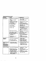
TROUBLESHOOTING
CHART
CAUSE
PROBLEM
CORRECTION
Willnotstart
1. Out of fuel,
2. Engine not =CHOKED"
properly.
3. Engine flooded.
1. Fill fuel tank.
2. See "TO START ENGINE"
in Operation section.
3. Wait several minutes
before attempting to start.
4. Bad spark plug.
4. Replace spark plug.
5. Dirty air filter.
5. Clean/replace air filter.
6. Dirty fuel filter.
6. Replace fuel filter.
7 Water in fuel.
7. Drain fuel tank and
carburetor, refill tank with
fresh gasoline and replace
fuel filter.
8. Loose or damaged wiring.
8. Check all wiring.
9. Carburetor out of adjustment 9. See "To Adjust Carburetor"
in Service Adjustments
section.
10.Contact a Sears or other
10. Engine valves out of
adjustment.
qualified service center.
Hard to start
1. Dirty air filter.
2. Bad spark plug.
3. Weak or dead battery.
4. Dirty fuel filter.
5. Stale or dirty fuel.
6. Loose or damaged wiring.
7. Carburetor out of adjustment
8. Engine valves out of
adjustment.
Enginewill not
turn over
1. Clutch/brake pedal not
depressed.
2. Attachment clutch is
engaged.
3. Weak or dead battery.
9. Faulty operator presence
switch(es).
1. Depress clutch/brake
pedal.
2. Disengage attachment
clutch.
3. Recharge or replace
battery.
4. Replace fuse.
5. Clean battery terminals.
6. Check all wiring.
7. Check/replace ignition
switch.
8. Check/replace solenoid or
starter.
9. Contact a Sears or other
qualified service center.
1.
2.
3.
4.
1.
2.
3,
4.
4.
5.
6.
7.
Blown fuse.
Corroded battery terminals.
Loose or damaged wiring.
Faulty ignition switch.
8. Faulty solenoid or starter.
Engine clicks but
will not start
1. Clean/replaca air filter.
2. Replace spark plug.
3. Recharge or replace
battery.
4. Replace fuel filter,
5. Drain fuel tank and refill
with fresh gasoline.
B. Check all wiring.
7. See "To Adjust Carburetor"
in Service Adjustments
section.
8. Contact a Sears or other
qualified service center.
Weak or dead battery.
Corroded battery terminals.
Loose or damaged wiring.
Faulty solenoid or starter.
28
Recharge or replace battery
Clean battery terminals,
Check all wiring.
Check/replace solenoid or
starter.
TROUBLESHOOTING
PROBLEM
Loss of power
CHART
CAUSE
CORRECTION
1. Cutting too much grass/too
fast.
2. Throttle in "CHOKE"
position.
3. Build-up of grass, leaves
and trash under mower.
4. Dirty air filter.
5. Low oil level/dirty oil.
6. Faulty spark plug.
7. Dirty fuel filter.
8. Stale or dirtyfuel.
9. Water in fuel.
10.Spark plug wire loose.
11. Dirty engine air screen/fins.
12. Dirty/clogged muffler.
13.Loose or damaged wiring.
14. Carburetor out of
adjustment.
15. Engine valves out of
adjustment.
Excessive
vibration
1. Worn, bent or loose blade.
2. Bent blade mandrel.
3. Loose/damaged part(s).
1. Set in "Higher Cut" position/
reduce speed.
2. Adjust throttle control.
3. Clean underside of mower
housing.
4. Clean/replace air filter.
5. Check oil level/change oil.
6. Clean and regap or change
spark plug.
7. Replace fuel filter.
8. Drain fuel tank and refill with
fresh gasoline.
9. Drain fuel tank and carbure
tor, refill tank with fresh
gasoline and replace fuel
filter.
10.Connect and tighten spark
plug wire.
11.Clean engine air screen/fins.
12. Clean/replace muffler.
13.Check all wiring.
14.See "To Adjust Carburetor"
in Service Adjustments
secfion.
15.Contact a Sears or other
qualified service center.
1. Replace blade.
Tighten blade bolt.
2. Replace blade mandrel.
3. Tighten loose part(s).
Replace damaged parts.
Engine continues
to run
when operator
leaves seat with
with attachment
clutch engaged
1. Faulty operator-safety
presence control system.
1. Check wiring, switches and
connections. If not
contact a Sears or other
qualified service center.
Poorcut-uneven
1. Worn, bent or loose blade.
1. Replace blade. Tighten
blade bolt.
2. Level mower deck.
3. Clean underside of mower
housing.
4. Replace blade mandrel.
5. Clean around mandrels to
open vent holes.
2. Mower deck not level.
3. Buildup of grass, leaves,
and trash under mower.
4. Bent blade mandrel.
5. Clogged mower deck vent
holes from buildup of
grass, leaves, and trash
around mandrels.
29
TROUBLESHOOTING
PROBLEM
Mowerbladeawill
not rotate
CHART
CAUSE
CORRECTION
1. Obstruction in clutch
mechanism.
2. Worn/damaged mower
drive belt.
3, Frozen idler pulley.
4. Frozen blade mandrel.
1. Remove obstruction.
2. Replace mower drive belt.
3. Replace idter pulley.
4, Replace blade mandrel
Poor grass
discharge
1. Place throttle control in
"FAST" position.
2. Travel speed too fast.
2. Shift to slower speed.
3. Wet grass.
3. Allow grass to dry before
mowing.
4. Mower deck not level.
4. Level mower deck.
5. Low/uneven tire air
5. Check tires for proper air
pressure.
pressure.
6. Worn, bent or loose blade.
6. Replace/sharpen blade.
Tighten blade bolt.
7. Clean underside of mower
7. Buildup of grass, leaves
and trash under mower.
housing.
8. Mower drive belt worn.
8. Replace mower drive belt.
9. Blades improperly installed. 9. Reinstall blades sharp edge
down.
10.Improper blades used.
10.Replace with blades listed
in this manual.
11.Clean around mandrels to
11.Clogged mower deck vent
holes from buildup of grass,
open vent holes.
leaves, and trash around
mandrels.
Headlight(s) not
working
if so equipped)
1.
2.
3.
4.
1. Engine speed too slow.
Switch is "OFF".
Bulb(s) burned out.
Faulty light switch.
Loose or damaged wiring.
5. Blown fuse.
3artery will not
:harge
1. Bad battery cell(s).
2. Poor cable connections.
3. Faulty regulator
(if so equipped).
4. Faulty alternator.
Engine"backfires"
Nhenturning
_ngine"OFF"
1.
2.
3.
4.
Turn switch "ON".
Replace bulb(s).
Check/replace light switch.
Check wiring and connections.
5. Replace fuse.
1. Replace battery.
2. Check/clean all connections.
3. Replace regulator.
4. Replace alternator.
1. Engine throttle control not
set at "SLOW" position
for 30 seconds before
stopping engine,
30
1. Move throttle control to
"SLOW" position and allow
to idle for 30 seconds before
stopping engine.
TRACTOR - - MODEL NUMBER 917.272073
SCHEMATIC
_D
I
L
_
}
..........
w_,Tt
/\.L
- _
BAGrrER_
y
A2
....
___
SC_ENOID
CLUTCH / BRAKE
/
,
_1
"
c_
'
__
_
_
i
,
,
_UEL
...............
SEAT SWITCH
_,
'
k,
_A_
....
_
,
|
'
30
'
_"
'
_R_TO_
PRESENCE RELAy #1
,, ,_) _,
_P
.( \\
_
z
IGNITION
/
CE
_y#2
I
j)
v_o_
UNIT
OPERATOR
\
:_
OPERATOR
_.
,
SWITCH
RELAy
.-_
-"
NON-REMOVABLE
_
2
'---
PRESENCE REL&Y #3
I
TWIN CYL, ENGINES)
(2 PLUGS ON
i
REMOVABLE
WIRING INSULATED
CUPS
NOTE: IF WIRING INSULATED SLIPS WERE REMOVED FOR
CONNECTIONS
CONNECTIONS
SERVICING OF UNIT, THEY SHOULD BE REPLACED TO
PROPERLY SECURE YOUR WIRING
31
TRACTOR - - MODEL NUMBER 917.272073
ELECTRICAL
~
32
TRACTOR - - MODEL NUMBER 917.272073
ELECTRICAL
KEY
NO.
PART
NO.
DESCRIPTION
1
2
8
16
21
22
24
25
26
27
28
29
3O
33
40
41
42
43
45
52
81
163465
74760412
156417
161343
175688
4152J
4799J
146147
175158
73510400
4207J
160784
175566
140403
170219
71110408
131563
175141
122822X
141940
109748X
Battery
Bolt Hex Hd 1/4-2Ounc x 3/4
Case BatteP/
Switch, Intedock
Harness Asm Light W/4152J
Bulb Light #1156
Cable Battery 6 Ga 11" red
Cable Battery 6 Ga w/16 wire red
Fuse
Nut Keps Hex 1/4-20 Unc
Cable Ground 6 Ga 12" black
Switch Plunger Non'hal Op Olive
Switch Ign
Key Ign
Harness Ign
Bolt BIk. Fin Hex 1/4-20 Uric x 112
Cover Terminal Red
Solenoid
Ammeter Rectangular 15 Amp
Protection Wire Loop
RelayAsm
NOTE:
All component dimensions given in U.S. inches
1 inch = 25.4 mm
33
TRACTOR
- - MODEL NUMBER 917.272073
CHASSIS AND ENCLOSURES
34
TRACTOR - - MODEL NUMBER 917.272073
CHASSIS AND ENCLOSURES
KEY PART
NO. NO.
DESCRIPTION
1
2
3
5
9
10
11
13
14
17
18
25
26
28
29
30
31
37
38
39
58
60
64
74
114
115
142
143
144
145
159
166
206
207
208
211
212
--
Chassis
Drawbar
Screw 3/6-16 x 314
Bumper Hood/Dash
Dash
Bolt, Carriage 3/8-16 x 3/4
Panel Dash, L.H.
Panel. Dash, R.H.
Screw Thdrct 3/6-16 x 1/2
Hood Assembly
Bumper Hood
Washer 13/32 x 13/16 x 12 Gauge
Nut
Grille
Lens
FendlFtrest
Bracket, Fender Support
Screw Thdrol 5/16-18 x 1/2
Pivot Bracket Assembly, Rear
Bracket Pivot Laser Lt
Duct Air Engine
Bolt Rdhd Sqnk 318-16 UNC x 1
Dash Lower STLT
Nut Crownlock 3/8016 UNC
Keeper Belt Rear Lh Stl P930
Screw 318-16 x 1-114
Plate Reinforcement STLT
Bracket Swaybar Chassis
Bracket Pnt Footrest STLT
Rod Pivot Chassis/Hood
CupholderStltBlack
Screw Hwhd Hi-Lo #13-16 x 3/4
Bo6 Shoulder 5/16-18 TT
Screw Thriml 5/16-18 x 112 Tytt
Screw Thdrol 3/8-16 x 1/2
Nut Hex Flange Lock
Insert Lens Reflective
Plug, Button
174619
176554
17060612
155272
168337)(013
S'rD533710
155927
172107X010
17490608
174330X558
126S38X
19131312
$113541437
175049
174332X599
164919;(558
139976
17490508
169834
174714
150127
72140606
154798
STD541437
158112
17060620
165867
154866
154207
156524
t55123X428
164863
170165
17670508
17670608
145212
175143
54793
NOTE: All component dimensions given in U.S. inches
1 inch = 25.4 mm
35
TRACTOR
- - MODEL NUMBER 917.272073
GROUND DRIVE
;I
212
il
66
4_65
36
116
TRACTOR
-- MODEL
NUMBER
917.272073
GROUND
DRIVE
KEY
NO.
PART
NO.
1
Transaxle (See Breakdown)
Peedess 206-545C
146682
Spring, Return, Brake
123666X
Pulley, Transaxle
1200G028
Ring, Retainer
12152OX
Strap,Torque
17060512
Screw 5/16-16 x 3/4
165866
ROd Shifter Fender STLT
STD561210 Pin, Cotter
105701X
Washer, Shift Plat_
74550412
Bolt 1/4-28 UNF W/Patch Gr. 8
10040400
Washer Lock Hvy Helical
STD541431 Nut Lock Hx W/Ins 5/16-18 x Gr.5
STD523710 Bolt Fin Hex 3/8-16UNC x 1 Gr. 5
STD541437 Nut
10_33X
Knob
130804
Rod, Brake
$TD541237
Nut
106889X
Spring, Brake Rod
s'rD551037
Washer
STO561210 Pin
175765
Rod, Parking Brake
71673
Cap, Padring Brake
169592
Bracket, Transaxle
STD523107 Bolt
175578
Shaft Assembly, Foot Pedal
120183X
Bearing, Nylon
STD551062 Washer
STD571810 Roll Pin
165936
Pulidy, Composite, Flat
74760648
Bolt
175461
Spacer, Sp_itSteel
175566
Keeper, Belt, Idler
19131312
Washer 13/32 x 13/16 x 12Ga.
127783
Pulley, Idler, V-Groove, Plastic
154407
Bellcrank Clutch Grnd Dry Stl
123205X
Retainer, Belt
STD523715 Bolt
STD541437 NutCrownLock3/6-16UNC
$3"D541431 NutCrownLocksi16-18UNC
105710X
Link, Clutch
105709X
Spring, Clutch Return
17060616
Screw 3/8-16 x 1.0
130801
V-Belt, Ground Drive
169691
Keeper, Beg, Center Span
17060612
Screw 3/8-16 x 3/4
88836
Cover, Pedal
2
3
4
5
6
8
10
11
13
14
16
16
19
21
22
24
25
26
27
28
29
30
32
34
35
36
37
38
39
40
41
42
47
48
49
50
51
52
53
55
56
57
59
61
62
DESCRIPTION
KEY
NO.
63
64
65
66
70
74
75
76
77
78
79
80
81
82
83
84
85
89
90
96
112
113
116
120
145
150
151
156
158
159
161
162
163
164
165
166
168
169
170
197
198
202
212
PART
NO.
175410
71170764
9TD551143
154778
134683
137(237
121749)<
STD581075
123583X
121748X
$1_580025
145090
165592
165711
19171216
166231
150360
158391)(428
124346X
STD624003
19091310
127265X
72140608
73900660
74490540
175456
19133210
166003
165589
165494
72140406
73680400
74780416
19091010
165623
166880
165492
165580
173898
169613
169593
72110612
145213
DESCRIPTION
Pulley, Engine
Bo6, Hex 7/16-20 x 4 Grade 5
Washer
Keeper, Belt, Engine, Fool Proof
Guide, Mower Drive Belt, R.H.
Spacer, Axta
Washer 25/32 x 1-1/4 x 16 Ga.
E4Ring
Key, Square 2.0 x .1845/1865
Washer 25/32 x 1-5/8 x 16 Ga
Key Woodruff
Arm, Shift
Shaft Asm Cross Tapered 650 20
Spring,Torsion
Washer 17132 x 3/4 x 16 Ga.
Link Transaxle
Nut, Nylock
Console, Shift, STLT
Nut, Self-Thding, Wsh Hd 1/4
RetainerSpringl"
Washer 9/32 x 3/4 x 10 Ga.
Strap Torque 90 Degrees
Boti Rdhd Sqneck 3/6-16 x 1
Nut Lock Fig. 3/6-16 Uno
Boll Hex Flghd 5/16-18 Gr. 5
Spacer Retainer
Washer 13/32 x 2 x 10 Ga.
Washer Srrted 5/161D x 1.125
Bracket Shift Mount
Hub Tapered Flange Shift Lt
Bolt Rdhd Sqnk 1/4-20 x 3/4 Gr.5
Nut Crownlock 114-20 Unc
Bolt Hex Fin 1/4-2gUnc x 1 Gr 5
Washer 8/8 x .281 x 10 Ga
Bracket Pivot Lever
Screw 5/16-16 x 5/6
Bolt Shoulder 9116-16 x .561
Plate Fastening Lt
KeeperBeltTransaxidGear
NylinerSnap-ln5i81D
Washer Nyliner 7/8 ID x .105 Hd
Bolt Carr. SH 3/8-16 x 1-1/2 Gr. 5
Nut Hex Flange Lock
NOTE: All component dimensions given in U. S. inches
1 inch = 25.4 mm
37
TRACTOR
- - MODEL NUMBER 917.272073
STEERINGASSEMBLY
o_'-.:::_--g::oi
38
TRACTOR
- - MODEL NUMBER 917.272073
STEERINGASSEMBLY
KEY PART
NO. NO.
DESCRIPTION
t
2
3
4
5
6
7
8
9
10
11
13
15
17
26
25
29
30
32
36
37
38
39
40
41
42
43
44
46
47
51
54
63
65
67
68
71
82
85
88
91
Steering Wheel
Axle Assembly STMP Dropped STL
Spindle Assembly, L.H.
SpindLeAssembly, R.H.
Bearing, Race, Thrust, Hardened
Washer 25/32 x 1-5/8 x 16 Gauge
Washer 27/32 x 1-114 x 16 Gauge
Ring, Klip
Bearing, Steering Column
Draglink
Washer, Lock
Spacer Beadng ASle Front
Nut, Hex Flange Lock
Shaft Assembly, Steering
Bushing, Link, Drag
Washer 13/32 x 7/8 x 16 Gauge
Screw 3/8-16 x 3/4
Pin Cotter
Rod,Tie
Bushing, Steering
ScJew
Insert, Steering Wheel
Washer 13/32 x 2-3/8 x 12 Gauge
Nut Lock Center 3/8-24 Unf
Adaptor, Steering Wheel
Boot, Steering Shaft
Washer 25/32 x 1-1/4 x 16 Gauge
Extension Shaft Steedng LR.LT
Cap, Spindle
Fitting, Grease
Nut Lock HexwSns. 5/16-18 UNC
Bolt Fin Hex 5/16-18 UNC x 1-1/4
Bolt, Fin Hex 3/8-16 UNC x 1 Gr 5
Spacer Brace Axle
Bolt RDHD Sqnk 3/8-16 x 2-1/4
Axle, Brace
Steering Asm.
Bracket Susp, Chassis Front
Fastener ChdstmasTree
Bolt Shoulder 7/16-20 Unc
Clip Steedng
139768
154427
169840
169839
6266H
121748X
19272016
12000029
3366R
175121
STD551137
136518
145212
177876
126847X
19131416
17060612
_1210
130465
155099
152927
139769
19133812
ST[To41537
100711L
145054)(428
121749X
153720
121232X
68.55M
STD541431
74780520
STD523710
160367
72140618
169827
175146
169835
133835
175118
175553
NOTE: All component dimensions given in U.S. inches
1 inch = 25.4 mm
39
TRACTOR
- - MODEL NUMBER 917.272073
ENGINE
OPTIONAL
EQUIPMENT
Spark Arrester
KEY
NO.
PART
NO.
1
2
17(_548
17720410
3
......
4
13
14
16
23
29
31
32
33
159420
12-041_3
148456
ST[T351237
169837
137180
109202)(
158990
123487X
DESCRIPTION
Control, Throttle
Screw, Hex Head, Threed
Cutting 1/4o20 x 5/8
Engine, (See Breakdown)
KohlerModelCV491o27501
Muffler
Gasket
Tube Drain Oil Easy
Washer
Shield Bm/Dbr Guard
Arrestor. Spark
Tank, Fue_
Cap Assembly. Fuel Sears, Vented
Clamp, Hose
23
KEY
NO.
PART
NO,
37
38
40
44
137040
148315
124028)(
17670412
45
46
77
80
81
101
105
17000612
19091416
19101216
74760508
73510400
M73030800
17120616
DESCRIPTION
Line, Fuel
Plug Drain Oil Easy
Bushing, Snap, Fuel Line
Screw, Hex Washer Head,
Thd., Roll. 1/4-20 x 3/4
Screw Hxwsh Thdr 3/8-16 x 3/4
Washer 9132 x 7/8 x 16 Ga
Washer 5/16 x 3/4 x 16 Ga.
Bolt Hex Hd 5/16-18 Unc x 1/2
Nut Keps Hex 114-20 Unc
NutFlangeM8-1.25Non-LkZinc
Screw 3/8-16 x 1
NOTE: All component dimensions given in U.S. inches
1 inch = 25.4 mm
4O
TRACTOR
- - MODEL NUMBER 917.272073
SEATASSEMBLY
\
i
24
; ;
I
I
•
i_
25
12
KEY PART
NO. NO.
DESCRIPTION
1
2
3
4
5
6
7
8
9
10
11
12
Seat
Bracket Pnt Pivot Seat (bik)
Boit Fin Hex 3/6-16unc X 1
Washer 13/32 X 3/4 X 10 Ga
Clip Push In Hinged
Nut Hex Lock w/Ins 3/8-16 Unc
Spring Seat Cprsn 2 250 BIk Zi
Screw 3/8-16 X 1
Washer 13132 X 1 X 14 Ga
Pan Pnt Seat (blk)
Knob Seat Adj Wingnut
Bracket Pnt Mounting Switch
140123
14(_a51
71110616
19131610
145006
$31_41437
124181X
17006616
19131614
174894
166369
121246)(
KEY
NO.
13
14
15
16
17
21
22
24
25
PART
NO.
121248X
72050412
134300
121250X
123976)(
171852
STO541431
19171912
127018)(
DESCRIPTION
Bushing Snap B]k Ny150 Id
Bolt Rdhd Sht Nk 1/4-20x1-1/2
Spacer Split 28 X 96 Zinc
Spring Cprsn 1 27 SIk Pnt
Nut Locit 1/4 Lge Fig Gr 5 Zinc
Boit Shoulder 5/16-18 Unc-2A
Nut Hex Lock w/ins 5116-18
Washer 17/32 X 1-3/16 X12Ga.
Bolt Shoulder 5/16-18 X 62
NOTE: All component dimensions given in U.S, inches
1 inch = 25.4 mm
41
TRACTOR - - MODEL NUMBER 917.272073
DECALS
13
1
13
6
3
11
10
11
2O
8
12
KEY PART
NO. NO.
DESCRIPTION
KEY PART
NO. NO.
DESCRIPTION
1
2
3
4
5
6
7
8
9
10
Decal, Oper. Instr,
Decal,Replacement
Decal, Hood, R.H.
Decal, Hood, LH.
Decal, Battmy
Oecal, Customer Maintenance
Decal, HP Engine
Decal, Mower Srs
Decal, Fender, Craftsman
Decal,Fender Danger
11
12
13
14
20
----*-
Decal, Hood Side
Decal, V-Belt Drive Schematic
Decal, Dash Panel
Decal, V-Belt Schematic
Decal Batted/Dngr/Psn Eng
Decal, Lift Handle
Pad Footrest LH STLT
POd Footrest RH STLT
Owner's Manual, English
Owner's Manual, Spanish
156368
171764
177333
177334
138047
133644
177367
172331
163204
156439
177325
146046
177353
160396
149516
138311
165800X428
165799X42lt
178396
178397
WHEELS & TIRES
5,8
4,10
11
KEY PART
NO. NO.
DESCRIPTION
1
2
3
4
5
6
7
8
9
10
11
--
Cap Value Tire
Stem Value
Tire F Ts 15 X 6 0 - 6 Servk:e
Tube Inner Front #35060
Rim Asm 6"front White Se_,ice
Fitting Grease
Beadng Flange
Rim Asm 8"rear White Service
Tire R Ts 20 x 10-8 Service
Tube Rear 9 5 X 8 Service
Cap Axle BIk 1 50 X 1 00
Sealant, Tire (10 oz. tube)
59192
_5139
106222X
59904
106732X427
278H
9040H
106108X427
122082X
7152J
104757X428
144334
NOTE: All component dimensions given in U.S. inches
1 inch = 25.4 mm
42
TRACTOR
- - MODEL NUMBER 9t7.272073
LIFTASSEMBLY
,3
J
7
13
2
11 19__I
6 13
2O
2O
15
15
KEY
NO.
PART
NO.
1
159460
2
3
4
5
6
7
8
11
12
159471
105767X
12000002
192'i1621
120183X
125631X
122365X
139865
139866
DESCRIPTION
Washer Asm Inner Spring W/
Plunger
Shaft Asm. Lift
Pin Groove
E Ring #,5133-62
Washer 21/32 x 1 x21 Ga,
Bearing Nyk)ng
GdpHandleFluted
Button Plunger Read
Link Asm Lift L.H.
Link Asm Lift R,H.
KEY
NO.
PART
NO.
DESCRIPTION
13
15
16
17
18
19
20
31
32
S'FD624008
173288
73350800
130171
73800800
139868
163552
159865
73540600
Retalner Spring
Link Front
Nut Jam Hex 1/2-13 Unc
Trunnion BIkZinc
Nut Lock wA'Vsh1/2*13 Unc
ArmSuspension Mower
Retainer Spring
Bearing, Pvt. Lift
Nut Crownlock 3/8-24
NOTE: All component dimensions given in U.S, inches
1 inch = 25.4 mm
43
TRACTOR - - MODEL NUMBER 9t7.272073
MOWERDECK
_148
106_
34
_21
44
102
103 lOS
TRACTOR
- - MODEL NUMBER 917.272073
MOWERDECK
KEY PART
NO. NO.
1
2
3
165892
STD_33107
138017
4
5
6
8
9
10
11
13
165460
S_3624008
130832
850857
S]D551137
140296
134149
137645
14
15
16
18
19
20
21
22
23
24
25
26
27
28
29
30
31
32
33
34
35
36
37
40
44
45
46
48
49
50
51
52
53
54
55
56
59
128774
110485X
174493
72140505
132827
159770
S]_541431
134753
131267
105304X
123713X
110452X
130968X428
19111016
131491
157722
129963
153535
137266
STD533717
133835
131494
S]D551037
STD541437
140088
STD624803
137729
133944
174284
131340
STD541410
139888
131845
133943
t 55046
165723
141043
DESCRIPTION
Mower Deck Assembly, 42"
Bolt
Bracket Assembly,Sway Bar,
Front
Bracket Sway Bar 38/42" Deck
RetainerSpring
Arm, Suspension, Rear
Bolt, Hex 3/8-24 x 1.25 Gr. 8
Washer, Lock
Washer, Hardened
Blade, Mulching
Sha6 Assembly, Mandrel,
Vented
Housing, Mandrel, Ventad
Bearing, Ball, Mandrel
Stripper, Vented Mower Deck
Bolt, Carriage 5/16-18x5/8
Bolt, Shoulder
Baffle. Vortex
NutCrownlock5/16-18UNC
Stiffener Bracket
Bracket, Deflector
Cap, Sleeve
Spring, Torsion, Deflector
Nut, Push
Shield, Deltector
Washer 11132x5/8x16Ga.
Red,Hinge
ScrewThdrolWasher Head
Washer, Spacer
Pulley, Mandrel
Nut. Toplcck, Flanged
Bolt
Fastner, Christmas Tree
Pulley, Idler, Flat
Washer 13/32x13/16x16Ga.
NutCrownlock3/5-16UNC
Guard, Mandrel, LH.
Retainer
Screw, Thd. RoLI 1/4-20x5/8
Washer.Hardened
Roller Assembly, C am Follower
Bolt, Shoulder #10-24 Grade 5
Locknut
Bolt, Shoulder 5/16-18 UNC
Arm Assembly, Pad, Brake
Washer, Hardened
Arm, idler
Spacer, Retainer
Guard, TUV Idler
KEY PART
NO. NO.
67
68
92
101
102
103
104
105
106
111
112
113
114
115
116
117
118
119
121
129
130
131
142
143
144
145
146
147
148
149
150
151
152
153
154
155
156
157
158
159
**
-°
149846
144959
STO541437
136420
71081010
19061216
$1_.51110
160793
2029.1
155197
155198
17060614
7351_o00
72110504
4898H
165746
73930600
19121414
143723
19131312
STD523710
STD533710
165890
157109
158634
165888
171977
131335
169022
165898
19091216
169670
169676
165674
165675
169671
169672
169669
17720410
72140614
130794
169583
DESCRIPTION
Knob Custom Oval
V-Belt
Nut
Mulcher Cover
Screw
Washer #10
Washer, Lock
Latch Assembly, Bagger
Nut, Weld
Bracket Gauge Wheel Lh
Bracket Gauge Wheel Rh
Screw 5/16-18 Unc
Nut Keps 5/16-18 Unc
Bolt Cart 5/16-Unc x 112
Bolt Shoulder
Wheel Gauge Std
NutCentedock3/8-16Unc
Washer 3/8 x 718 x 4 Ga.
Bracket Extruded Gauge Wheel
Washer13/32x13/16x12Ga.
Bog, Fin Hex 3/8-16 UNC x 1 Or. 5
Bolt. RdhdSqnk3/8-16UNCx1
Arm Spring Brake Mower
Bracket Ann Idler 42"
Keeper Belt 42" Clutch Cable
PulleyldlerRat
SoltCarrJageldler
Spring Extension
Spring Return Idler
Retainer Spdng Yellow Zinc
Washer 9132 x 3/4 x 16 Ga.
Bracket Clutch
Cable Clutch 42 Ln
Washer Flat 3/8" Type B
Spring Retainer
SpringRetentionLever
Spacer
Rod Clutch
Screw Hex Thd Cut 1/4-20 x 5/8
BoltRdhdSqn3/8*16Uncx3/4
Mandrel Assembly (Includes Key
Numpers 8-10, 13-15, 31 and 32)
Mower Deck, Complete (Standard
Deck, Order Separately Mulcher
Plate and Gauge Wheel
Components, Key Nos. 101o106
and 111-121)
NOTE: All component dimensions given in U.S. inches
1 inch = 25.4 mm
45
TRACTOR
--MODEL
NUMBER
917.272073
PEERLESS
TRANSAXLE
- - MODEL NUMBER206-545C
57
29
157
41A
46
TRACTOR
- - MODEL NUMBER 917.272073
PEERLESS TRANSAXLE- - MODEL NUMBER206-545C
KEY
NO.
PART
NO.
1
2
3
4
5
6
6A
7
8
8A
9
10
11
12
13
772147
780086A
770128
776395
776409
778364
778369
778330
792180
792047
784352
784378
778334
778309
778368
14
778368
15
17
18
20
21
22
25
25A
26
27
28
29
29A
29B
29C
30
31
778370
786188
786102
792077A
792078
792079
792073A
792177
792125
792035
788040
780072
780160
780051
780199
780108
780001
31A
32
34
35
35A
36
37
38
39
40
780195
788083
780194
780193
780197
796075
790007
799021
786026
792076A
DESCRIFI1ON
Transaxle Cover
Needle Bearing 5/5"
TransaxleCase
Countershaft
Output Shaft
Spur Gear (38 teeth)
Spur Gear (15 teeth)
Spur Gear (11 teeth)
Shift Key
Woodruff Key #9
Shift Collar
Shift Rod & Fork
Bevel Gear (30 teeth)
Input Bevel Pinion (13 teeth)
Bevel Gear (13 teeth)
(Include. 14)
Bevel Pinion (13 teeth)
(Include. 13)
Ring Gear (43 teeth)
Dnve Pin
Spacer 1,130 X ,695
Ball 5/15" dia
Set Screw 3/8 - 16 x 3/8"
Spring ,310 OD x ,625 L
Screw 114 - 20 x 1-1/4"
Screw 114o20x 1-3/8"
Retaining Ring (pkg of 2)
Retaining Ring
Retaining Ring
Thrust Washer .627 ID x.031W
Thrust Washer .762 ID x.031W
Thrust Washer .762 ID x.031W
Anti-Rotation Washer .632
Cup Washer 1.127 ID x .032W
Flat Washer .750 ID x .056W
(UseAs Needed)
Flat Washer ,750 ID x .062W
Oil Seal 5/8"
Bushing ,563
Flanged Bushing 518" ID
Flanged Bushing ,751
Brake Disk
Brake Pad Plate
Brake Pad (pkg of 2)
Dowel Pin
Flat Washer .312 ID x .059W
_
NO.
PART
NO.
41A
42
4ZA
43
44
45
46
47
48
49
50
51
52
53
54
56
57
58
59
60
61
65
66
67
69
70
71
71B
76
77
79
82
83
85
87
150
157
180
9GO
790079
792073A
792085A
792075
790025
786066
786086
774690
774691
778356
778338
778354
778352
778350
778346
778355
778337
778353
778351
778349
778345
780189
776422
776396
792170
786187
788069
788092
780090
788078/=,
792144
778333
778338
792154
788089A
788093A
788088A
730229A
794712
DESCRIPTION
Brake Lever
Screw 1/4 - 20 x 1-1/4"
Screw 1/4 - 20 x 2 1/4"
Locknut 5 / 16 - 24
Brake Pad Holder
Spacer ,2625 x 1.0
Brake Lever Bracket
Axle (11-15 116" Long)
Axle (16 - 1 / 2" long)
Spur Gear (29 teeth)
Spur Gear (27 teeth)
Spur Gear (23 teeth)
Spur Gear (19 teeth)
Spur Gear (16 teeth)
Spur Gear (15 teeth)
Spur Gear (11 teeth)
Spur Gear (13 teeth)
Spur Gear (17 teeth)
SpurGear(21teeth)
Spur Gear (24 teeth)
Spur Gear (25 teeth)
Fiat Washer ,563 ID x ,062W
Input Shaft
Shifter & Brake Shaft
Retaining Ring
Spacer.890
Square Cut Ring
"O" Ring
Flat Washer 1,128 ID x .058W
Inverted Retaining Ring
Bpdng .430 OD x .5000 L
Bevel & Spur Gear (30 & 13 teeth)
Spur Gear (27 teeth)
Oil Fill Plug
Oil Seal 9 / 16"
Liquid Gasket RTV Silicone
Oil Seal 3/4"
Gear Oil80W9O
Replacement
M ST - 206-545C Transaxle
NOTE: All component dimensions given in U,S. inches
1 inch = 25.4 mm
47
TRACTOR - - MODEL NUMBER 917.272073
KOHLER ENGINE-MODELNUMBERCV491, TYPE NUMBER27501
CYLINDER HEAD, VALVE AND BREATHER I
/
I
lg
10
48
TRACTOR
- - MODEL NUMBER 917.272073
KOHLERENGINE-MODELNUMBER CV491, TYPE NUMBER 27501
CYLINDER
KEY PART
NO. NO.
1
25-351-01-S
2
12-755-94-S
3
4
5
10
11
12-411-03-S
12-041-10-S
12-017-01-S
12-g17-02-S
12-016-gl-S
12-016-02-S
X-75-23-S
812-318-36-S
925-186-01-S
12-599-g3-s
M-640034-S
12
13
14
15
16
12-089-34-S
12-173-01-S
12-755-03-S
12-468-05-S
12-112-13-S
17
12-086-15-S
18
19
20
X-426-9-S
12-326-03-S
M-645020*S
21
22
12-096-g7-s
M-545010-S
23
24
12-018-01-S
12-402-02-S
6
7
CRANKCASE
HEAD/VALVE/BREATHER
KEY PART
NO. NO.
DESCRIPTION
Lifter, valve (2)
Kit, c linder head Includes
4,6-1 ]_./Gaskets 1"_:041 01S (Qty. 2), 12 041 02-S, 12
041 03-S, & 12 041 08-S)
Rod, push (2)
Gasket, cylinder head
Valve, intake Std.)
Vave, ntake ,25)
Valve. exhaust Std.
Valve. exhaust .25
Plu , allen hd. pipe 1/8"
Cyl_der
Head
Arm, rocker (2)
Pivot, rocker arm (2)
Screw, hex, flange
M6xl.0x34 (2)
Sphng, valve (2)
Cap, valve spring (2)
Kit, retainer (2)
Washer, plain 13132"
Spacer, head bolt exhaust
port
Screw, hex, flange
M10xl,5x81
(5)
Clamp, hose (2)
Hose, breather
Screw, hex. flange
M6xl.0x20
(5)
Cover. valve w/nipple
Screw, hex. flange
M5x0.8xl0
Retainer, breather reed
Reed, breather
1
12-032-03-S
2
3
4
12-522J,9
12-445-02-S
M-839025-S
5
6
7
8
12-380-17-S
12-755-49-S
12-089-31-S
12-422-08-S
12-422-09-S
12-422-10-S
9
10
12-422-11-S
12-422-12-S
12-422-13-S
12-422-07-S
12-144-28-S
12-874-07-S
14
15
16
17
18
19
12-874-11-S
12-874-08-S
12-874-09-S
12-018-02-S
12-108-g7-s
12-108-08-S
12-108-09-S
12-067-11-S
12-067-06-S
12-380-01-S
12-043-g5-s
M-631005-S
12-144-02-S
52-139-09-S
12-755-64-S
20
21
22
23
X-25-102-S
12-032-01-S
M-631015*S
12°154-05-S
11
12
13
DESCRIPTION
Seal, crankshaft
Block, cylinder
(Use Short Block)
Strap, lifting
Screw, hex. flange
MSx1.25x25
Dowel. Locating (4)
Kit, camshaft _lncludes 7&8
S ring, actuattn
S_im. camshaft _A.R.) blue
Shim. camshaft A.R. red
Shim, camshaft IA.R./
_ellow
Shim,
A.R. _reen
ray
him, camshaft
camshaft
Shim,
camshaft {A.R,l
A,R.
lack
Shim, camshaft (A,R.) white
Shaft, balance
Piston wiring Set (Std,)
(Includes 11-12)
Piston wiring Set (,08 ram)
mm
Piston wiring Set ,25
,80 mm ))
Retainer, piston pin (2)
Ring Set (Std.)
Ring Set ,25
Ring Set 1:5Ol
Connecting Rod (Std.)
Connecting Rod .25)
P n, governor regu ating
Gear, governor
Washer, plain 6ram
Shaft, governor gear
Plug, cup
Kit. gov. cross shaft w/clip
(Includes 23)
Washer, plain 1/4"
Seal, governor cross shaft
Washer, plain 6ram
Clip, hitch pin
NOTE: All componentdimensionsgiven in U.S.
inches 1 inch= 25.4 mm
49
TRACTOR- MODEL NUMBER 917.272073
KOHLER ENGINE-MODELNUMBER CV491, TYPE NUMBER 27501
IGNITIONIELECTRICAL
I
BLOWER
HOUSING
AND
RAFFLESI
4
12
13
\
14
/
111--_
10
i-.
_
t --11
12
5O
S
TRACTOR- MODEL NUMBER 917.272073
KOHLER ENGINE-MODELNUMBERCV491, TYPE NUMBER27501
BLOWER
IGNITION/ELECTRICAL
KEY PART
NO. NO.
1
12-086-14-S
2
3
4
12-468-03-S
24-162-03-S
25-085-47-S
5
6
7
8
9
12-157-03-S
X-42-15-S
12-025-15-S
12-155-09-S
M-548025-S
10
237878-S
11
M-545020-S
12
13
14
15
12-154-06-S
41-403-09-S
X-22-11-S
M-639016-S
16 236602-S
17 12-132-02-S
18 X-728-1-S
19 M-545010-S
DESCRIPTION
Screw, hex. flange
M10x1,5x46
Washer, plain 3/8"
Screen, grass
So]t, shoulder M6X1,0X16
_4_
_:an
Key
Flywheel
Connector
Screw, hex. cap M5x0.8x25
(2)
Stator (Includes Screw,
hex. cap X-67-51-S (4)
&Terminal
25 452 01-S (2)
Screw, hex. flange
M5x0.8x20 (2)
Clip. cable (2)
Regulator, rectifier - 15 amp
Washer, lock 114"
Screw, hex. flange
MSx1.0x16 (2)
Connector
Spark Plug
Clip, cable (2)
Screw, hex. flange
M5x0.8xlO
(2)
Module, ignition
20 12-584-04-S
NOT ILLUSTRATED
12-176-45-S
Harness, w!r!ng
12-176-44-S
Harness. wiring
24-515-12-S
Lead, black (6" - 12 gauge12-518-35-S
X-67-51-S
25-452-01-S
insulated grip barrel eyelet
terminals
Lead, wh te 36" -18 gauge
- fully insulated push on
and uninsulated socket
terminals)
Screw, hex.cap 10-24 X 3/
4" (4)
Terminal
22" - 22 gau_e 11
4" un nslulated male. (side)
locking, push on tab) (4)
HOUSING
KEY PART
NO. NO.
1
M-545010-S
2
3
4
24-468-10-S
12-146-07-S
M-550010-S
5
6
7
5
9
24-096-05-S
12-027-76-S
12-063-18-S
25-154-02-S
12-0fi5-37-S
10
11
12-063-17-S
M-645016-S
12
12-063-01-S
NOT ILLUSTRATED
M-541050-S
& BAFFLES
DESCRIPTION
Screw, hex. flange
M5x0.8xl0
(6)
Washer. plain 114"
Plate, blower housing
Screw. hex. flange
M5x0.8xl0
Cover, pinion
Housth_, blower.
Baffle, intake side
Clip, mounting (3)
Screw, captive washerM5
X0.8 X20 3)
Baffle, cynderheed
Screw, hex. flange
M6x1.0x16 (2)
Baffle, cylinder
Nut, hex. flange
M5x0.8
AIR INTAKE/FILTRATION
KEY
NO.
1
2
3
4
5
6
PART
NO.
12-281-01-S
25-341-03-S
12-096-24-S
12-083-12-S
12-100-08-S
12-083-10-S
7
12-743-12-S
8
9
12-032-11-S
12-094-07-S
10
11
12-072-04-S
12-086-01-S
12
12-041-02-S
NOT ILLUSTRATED
12-113-53-S
NOTE:
inches
51
DESCRIPTION
Duct, ag
Knob, air cleaner cover
Cover, air cleaner
Precleaner, element
Wing Nut
Kit air cleaner element
(thcJudes 5-5)
Filter, element (thcludesS&8)
Seal 1-7116"
Base, air cleaner (Includes
11&12
Stud, mountng
pate
M6X1.0X75
Screw, #10 Hi-Lo thread
forming (2)
Gasket, air cleaner
Decal, air cleaner
All component dimensions
1 inch = 25.4 mm
given in U.S.
TRACTOR
- - MODEL NUMBER 917.272073
KOHLERENGINE-MODELNUMBER CV491, TYPE NUMBER27501
STARTING SYSTEM I
i ENGINECONTROLS
I
1
I
1
/
t!
11
OIL PAN
I LUBRICATION
I
11
19
18
52
TRACTOR
- - MODEL NUMBER 917.272073
KOHLER ENGINE-MODELNUMBERCV491, TYPE NUMBER27501
ENGINE
STARTING SYSTEM
KEY pART
NO. NO.
1
M-839070-S
2
25-098-07-S
3
4
5
6
7
8
12-756-54-S
12-227-18-S
12-170-05-S
12-221-01-S
12-227-13-S
12-211-01-S
DESCRIPTION
Screw, hex. flange
M8xl.25x70
2I
Starter assembly (Incudes
3-8
Kt, drive end
Cap, dnve end
Armature
Kit, brush & spring
Cap, commutator end
Bolt, hex. flange 1/4-20x45/8 (2)
OIL PAN/LUBRICATION
KEY PART
NO. NO.
1
12-038-01-S
2
3
4
5
6
25-755-13-S
12-153-03-S
12-153-02-S
12-123-04-S
M-645026-S
7
8
9
1O
12-153-01oS
25-162-07-S
12-096-03-S
M-54501B-S
11
12
13
14
15
16
17
25462-09-S
52-050-02-S
X-75-10-S
12-393-01-S
12-153-06-S
12-096-34-S
M-545016-S
18
19
12-032-03-S
24-086-16-S
20
24-gB6-17-S
21
12-199-56-S
CONTROLS
KEY PART
NO. NO.
1
2
3
12-079-11-S
12-237-01-S
24-086-43-S
4
M-664020-S
5
12-536-10-S
6
M-443025-S
7
M-443020-S
B
9
10
11
12-089-11-S
12-089-23-S
12-089-24-S
12-755-83-S
12
13
14
15
16
17
12-t00-07-S
52-211-04-S
12-090-28-S
25-t58-08-S
12-079-10-S
26-158-11-S
DESCRIPTION
Dipstick assembly (Includes
2-3
Kit, o fl cap (Includes 3)
O-Ring, oil fill ca P
C-Ring, upper oiIfill tube
Tube, oil fib
Screw, hex. flange
Mflx1.Ox25
O-Ring, lower oil fill tube
Screen, oil pickup
Cover, oil pickup screen
Screw, hex. flange
M5x0.8x16
Valve, oil pressure relief
Filter, oil
Plug, sq. hd. solid 318"
Pump, oil
O-Ring, oil pump cover
Cover, oil pump
Screw, hex, flange
M5xO.8x16 (',3)3
Seal, oil (P,T.O. end)
Screw, hex. flange
M8x1.25x45
(11)
Screw, hex. flange
M8x1.25x45
Assembly, oil pan (Incl.
11,14-17)
DESCRIPTION
Linkage, choke
Clamp, cable
Screw, thread forming
M5x0.8x16
Screw, lobed socket
M6xLOx2O (2)
Control, speed assembly
(Includes 6-9)
Screw, pan head
M4xO.7x25
Screw, pan head
M4x0.7x20
Spring. choke (2)
Spring, choke return
Spring, governor
Kit, governor lever (Includes
12-14)
Nut, hex flange 1/4 - 20"
Bolt, 1/4 - 20 X 1"
Lever, governor
Bushing, throttle linkage
Linkage, throtge
Bushing, throttle linkage
NOTE: All component dimensionsgiven in U.S.
inches 1 inch = 25.4 mm
53
TRACTOR
- - MODEL NUMBER 917.272073
KOHLER ENGINE-MODELNUMBER CV491, TYPE NUMBER27501
CRANKSHAFT
J
EXHAUSTJ
i -'
4
/
54
2
TRACTOR
- - MODEL NUMBER 917.272073
KOHLER ENGINE-MODELNUMBER CV491, TYPE NUMBER 27501
FUEL SYSTEM
KEY PART
NO. NO-
1
2
3
4
M-641060-S
X-22-11-S
M-629116-S
12-853-95-S
CRANKSHAFT
DESCRIPTION
Nut, hex. flange M6xl0 (2)
Washer, lock 1/4"
Stud M6x1,0x116 (2)
Kit, carburetor w/gasket
_ncludes 5-7, (qty 1)
ie, cable 12_,54-03-S,
Terminal 25-452-20-S)
5
12o041-02-S Gasket. air cleaner
6
12o053-107
Carburetor assembly
(For informationonly not
available separately)
(Includes Kit, float 12-75702-S Kit carburetor repair
12 -757- 03_S. Kit, Solenod
repair 12-757-33-S)
7
12o041-01-S
Gasket, carburetor (2)
8
12-265-06-S
Deflector, heat
9
X-426-9-S
Clamp, hose (6)
10 52-353-22-S
Line, fuel
11 25-050-03-S
Filter, fuel in-line
12 12-559-01-S
Kit, fuel pump (Includes 1315)
13 M-64502_-S
Screw. hex. flange
M6xl.0x20 (2)
14 25-041-09-S
Gasket. fuel pump (2)
15 12-112-05-S
Spacer, fuel pump
16 25-155-02-S
Connector, 90 degree hose
17 25-326-03-S
Connector, straight hose
15 12-353-01-S
Line, fuel 1.25
19 12-123-19-S
Line, fuel
20 M-545010-S
Screw, hex. flange
M5x0.8xlO
21 12-154-01-S
Clip
22 47-154-01-S
C_ipcable
NOT ILLUSTRATED
41-353-18-S
Line, fuel 2.7
M-561010-S Screw, thread forming
M5X0,8X10
12-757-02-S
Kit, float
12-757-03-S
Kit, c_rburetor repair
12-041-01-S
Gasket, carburetor
12-041-02-S
Gasket. air cleaner
12-041-05-S
Gasket, bowl
12-041-06-S
Gasket, bowl screw
12-032-06-S
Seal, solenoid
t2-757-33oS
Kit, sotenoid repair
12-041-06-S
Gasket, bowl screw
12-454-03-S
Tie cable
25-452-20-S
Terminal
12-518-37-S Lead, red. (37" 20 gaugeinsulated socket and
uninsulated socket
terminals)
KEY PART
NO. NO.
DESCRIPTION
1
2
Crankshaft
P_ug, cup
12-014-57-S
25-139-27-S
(Includes
2)
EXHAUST
KEY pART
NO. NO.
DESCRIPTION
1
Gasket,
12-041-03-S
exhaust
manifold
(3)
2
3
4
12-126-11-S
12-445-06-S
M-645025-S
Bracket muffler
Step, lifting
Srew, hex. flange Mexl.0x25
12-522-49
12-755-82-S
_h)ort Block
Gasket Set
NOTE:
All component dimensions given in U,S,
inches 1 inch = 25.4 mm
58
56
57
58
SUGGESTED
GUIDE FOR SIGHTING
SLOPES
FOR SAFE OPERATION
ONLY RIDE UP AND DOWN HILL,
NOT ACROSS HILL
15 ° MAX.
Operate your Tractor up and down the face of slopes (not
greater than 15°), never across the face. Make turns gradually to prevent tipping or loss of control. Exercise extreme
caution when changing direction on slopes.
For repair of major brand appliances in your own home...
no matter who made it, no matter who sold it!
1-800-4-MY-HOME
SM_ir_,
'J.vor night
(%800-4694663)
www.sears.com
To bring in productssuch as vacuums,
lawn equipment and electronicsfor repair, call for
the location of your nearest Sears Parts & Repair Center.
1-800-488-1222
Anytirne, day or night
www.sears.€;om
For the replacement parts, accessories and owner's manuals
that you need to do-it-yourself, call Sears PartsDirectSMf
1-800-366-PART
(1-800-366-7278)
www, sears.com/pa
6ar.- 11pmCST,
7 days a week
rtsdlrect
To purchase or inquire about a Sears Service Agreement:
1-800-827-6655
7 am. - 5 p, rn. CST, Mort.- Sat.
Para pedir se_/icio de reparacibn a dornicilio,
y para ordenar piezas con entrega a domicillo:
Au Canada pour service en fran_ais:
1-888-SU-HOGARSM
(1-888-784-6427)
1-877-LE-FOYER _u
(1-877-533o6937)
t HomeCentral ®
@ Sears, Roebuck and Co.
178396
01.23.01
RH
® Registered Trademark / TM Trademark of Sears. Roebuck and Co,
® M_rca Registrada ! r_ Marca de F_brica de Sears, Roebud_ and Co
Printed in U.S.A.