1
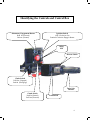
OWNERS MANUAL
www.prodriveoutboards.com
POPO
Box
949
Box
959
2702
Lake
Dauterive
2702
Lake
Dauterive Road
Road
Loreauville, LA 70552
Loreauville, LA 70552
PH#: 337-229-0034
PH#:337-229-2302
337-229-0034
FAX#:
FAX#: 337-229-2302
1
TO THE OWNER
Thank you for purchasing a “Pro-Drive Shallow Water Outboard”.
Your unit is designed for long life, dependability, ease of operation,
safety, and top performance that you deserve and expect.
Take time now to read this manual and the safety precautions.
Everyone who operates this unit must read and understand this manual.
The time you take now will prolong your units life and prepare you for
its safe operation.
Thanks again and enjoy.
Table of Contents
Desc.
•
•
•
•
•
•
•
•
•
•
•
Safety Instructions
Installation Instructions
Unit Component Identification
Identifying The Controls
Start Up
Operation Instructions
Reverse Procedure
Unit Maintenance
Prop Removal and Installation Instructions
Trouble Shooting Tips
Warranty Information
Page
3
4
5
6
7
8,9
10,11,12,13
14,15,16,17,18
19,20
21
22,23,24
2
Safety Instructions
IMPORTANT
Read and understand these instructions. They are for your safety. Failure
to follow these instructions may result in property damage, personal
injury, or death.
•
Read and understand engine manufacturer’s owners manual.
•
Attach safety kill switch lanyard to you before starting the engine.
(Attaching the safety kill switch is a suggestion only. Know your risks and
situation before electing to use or not to use Know the boating laws in your
state.)
•
Do not engage clutch while running engine out of water. Personal injury
can occur if prop is spinning in open air.
•
Keep legs and body clear from under tiller handle.
•
Engage clutch to forward at idle only.
•
Always disconnect the battery before servicing the engine.
•
Never touch or attempt to remove the propeller, until the battery is
disconnected.
•
Remember to follow all boating regulations and wear your personal
flotation device while on the water.
•
Never use this unit when under the influence of alcohol or any other drug.
3
Installation Instructions
After installing your motor on the boat transom use the aluminum transom saver plate
supplied with the unit, torque the boats to 25 ft. Lbs. of torque.
Located on the back of the transom bracket there are three sets of holes on each side.
Drill a 7/16” hole through the transom. One on each side in the hole most suited for your
boat. Use the 3/8” bolts and nuts supplied with your unit to secure the bracket in the
holes drilled.
4
Unit Component and Control Feature Identification
Engine
Tach / Hour
Meter
Tilt
Handle
Control
Box
Twist Grip
Throttle
Choke
Manual
Reverse
Release Pin
Tiller Handle
Tower
Housing
Power Trim and
Reverse Rocker
Reverse
Lock
Friction Knob
Trim
Cylinder
Cavitation
Plate
Transom
Bracket
Your PD# Is
Located Here
Prop
Skeg Plate
Lower Unit
5
Identifying the Controls and Control Box
Momentary Engagement Button
Push In (Forward)
Release (Neutral)
Iginition Switch
(Off / Clockwise On)
Continue Clockwise Engages Starter
Safety
Kill
Reverse Switch
Choke Switch
Pull Out (Engaged)
Push In (Disengage)
Twist Grip
Throttle
Clutch Switch
Push In (Neutral)
Pull Out (Forward)
Trim Switch
6
START UP
*Note: your engine is shipped without oil. Oil
must be added before starting your engine.
See the engine manual. (Check before adding
oil. Do not overfill)
•
•
•
•
Visually check unit for any loose, damaged or missing parts.
•
•
Pull out choke and turn ignition key clockwise to the start position.
•
•
•
Attach safety lanyard if electing to do so. (Check local laws.)
Check engine according to the engine owners / operators manual.
Make sure clutch is depressed (neutral position). *note engine will not start if
clutch is engaged.
Once engine has started push the choke back in and allow engine to warm
up.
After warm up, engage the clutch and accelerate by using the twist grip
throttle on the tiller handle and your on your way.
Remember only engage the clutch at idle. You may disengage the clutch at
any time. Engaging the clutch at high rpm against a log or blunt object can
damage the clutch and void the clutch warranty.
Momentary clutch engagement (forward) may be used by depressing the
black button while the clutch button (red button) is pushed in (disengaged)
*Note: Use ¼” fuel line and fittings with hose clamps to connect your engine fuel line to
your tank.
**Note: Due to new EPA Regulations on marine gas tanks, manufacturers
are required to design their tank vents to hold approx. 6 lbs of
pressure before venting. This poses a problem as most carburetor
valves only hold 3 lbs. We recommend you install quick disconnects
at the tank and remove when traveling or not in use.
7
Operation Instructions
Regular Operation
•
Make sure engine ignition is off.
•
Check engine oil.
•
Attach safety kill switch. (If electing to do so. Check local laws.)
•
Make sure clutch button is pushed in ensuring it is in neutral. (Note: Engine
will not start while the clutch button is pulled out.)
•
Pull choke as needed and start engine. Allow engine to warm up.
•
Set trim allowing the engine to be slightly above level with the boat.
•
Pull out the red button to engage the clutch to go forward.
Note: only engage the clutch button while the engine is at idle. Engaging the
clutch at high rpm’s can damage the clutch and void the clutch warranty.
•
While on step, adjust trim to the best performance for your boat. Once your
trim is set, there is no need to adjust it at any time, even while starting and
stopping in normal running conditions. Note: Do not try and submerge your
prop or cavitation plate while on step. Doing so will decrease performance.
Your prop is designed to run at the surface. (half of the prop is out of the water
while on step)
Footnotes: a) Tiller handle torque and slow speed indicates that the trim is set
too far down.
b) Extremely light tiller handle torque and speed loss indicates that
the trim is too high up.
8
Running In Grass, Hydrilla & Lillies With Water
Underneath.
•
While your boat is on step and running, no trim adjustment is needed.
•
Under extremely heavy conditions, you may need to trim down slightly, and
clear the prop by rasing the engine while getting on step. (Clearing the prop
may need to be done more than once in heavy vegetation while getting on
step.) Once on step, trim to normal running position.
Footnote: Raising the engine is done by pushing down on the tiller handle. If
needed, the tilt handle can also be pulled on simultaneously.
Running In Shallow Water To No Water On Soft Mud.
•
While your boat is on step and running no trim adjustment is needed.
•
To take off from a dry stop in these conditions, you will need to trim your
motor down to near maximum depth.
•
Engage the clutch and open the throttle fully.
•
Using your tiller handle, work the engine from left to right pushing mud
until your boat is moving at about walking speed.
•
Once you are at walking speed, trim up as you would under normal
conditions.
You will now be able to slow your throttle down to your desired speed.
•
Footnote: Should your engine load up (lose power) while trimmed down in the
Above conditions, trim up until the engine is
running normally again.
9
Reverse Operating Procedure
The concept is explained by comparing it to the same way a common ratchet and
socket set in your tool set works.
Below are some diagrams with explanations on how this system works.
First, you will have to adjust your friction knob by tightening it. This just like when
tightening a nut and bolt with a ratchet, some friction is needed to make the ratchet
mechanism work,
Step 1. While sitting, push your tiller handle with your right hand away from your
seated position. This will position your unit for reverse and allow you to access the
release pin.
10
Step 2. Pull the reverse release pin down. Pull the tiller toward you slightly, then
release the pin and continue pulling the tiller toward you until you here the unit
click. (Once you release the pin you will not have to pull the pin again until you are
ready to go back into the forward position.) Push the tiller handle away from you
again like in step 1 and repeat. When your reverse clicks for the fourth time your
pin will locate in the reversed locked position.
.
The pictures below show the unit rotating to reverse
11
This picture shows the release lever lock for units with hydraulic power trim in
the unlock position.
Step 3. Once the unit is in reverse, lock the trim down with the lever loc.
*Note: the reverse lever must not be locked when running in forward gear.
Repeat the above procedure to return to forward gear.
12
Important
While in reverse in deep water, (anything over 10 inches),
reverse gear should only be used at idle speeds. Full throttle
in deep water conditions could cause your boat to become
swamped.
13
Unit Maintenance
•
•
Lower unit oil should be checked every 20 hours . Use only SAE 80W-90 or
75W-90 gear lubricant API service GL-5 (A synthetic gear oil such as Royal
Purple may be used.)
Lower unit oil should be replaced once a year or every 50 hours.
Diagram A – Checking the Oil
(Every 20 Hours )
With motor level remove the top outer plug with 1/4” allen wrench.
Oil should flow out or you should be able to see it. Top off if needed
Replace the plug using teflon tape. Do not over tighten.
Oil
Level
Plug
Oil
Drain
Plug
14
PRO-DRIVE LOWER UNITS RECEIVED A MODIFICATION UPGRADE TO IT’S
LUBRICATION SYSTEM. THE GEAR SYSTEM IS STILL FILLED WITH OIL, HOWEVER
THE PROP SHAFT NEEDLE BEARING AND SEAL CHAMBER IS NOW FILLED WITH
GREASE.
* AN EP (EXTREME PRESSURE) GREASE IS RECOMMENDED. (WE USE CHEVON BLACK
PEARL GREASE EP NLGI 2. LUCAS RED N TACKY IS ALSO ANOTHER EP GREASE)
SEE THE ILLUSTRATION BELOW FOR DIRECTIONS.
REMOVE ANY GRASS
OR FOREIGN DEBRIS
FROM THE PROP
SHAFT BETWEEN THE
PROP AND LOWER
UNIT HOUSING. PUMP
GREASE INTO THIS
GREASE FITTING
EVERY 15 to 20 HOURS
GREASE WILL
APPEAR FROM SEAL
NUT IN FRONT OF THE
PROP WHEN FULL.
THIS IS THE AREA
WHERE THE DEBRIS
IS CLEARED.
THIS MODIFICATION WAS MADE TO INCREASE REAR SEAL LIFE IN EXTREME
CONDITIONS TO PREVENT OIL CONTAMINATION.
15
YOUR LOWER UNIT
TOP BEARING IS
LUBED BY GREASE
AND NEEDS TO BE
GREASED AT 15 TO 20
HOURS. THE GREASE
FITTING IS LOCATED
HERE. NOTE: 10 OR 12
PUMPS ARE NEEDED
AND YOU WILL NOT
SEE RETURNS.
GREASE PORT
GREASE PORT
16
The diagram below shows the grease ports of the reverse assembly.
These needs to be greased every 15 to 20 hours. Pump two shots of
grease into each. Reverse should be rotated and two shots of grease
applied to grease port 1 and 2 every click of the reverse until the
unit has been rotated a complete 360 degrees. Note: Failure too lube
reverse disc will cause drying and make the reverse operation
difficult sometimes not allowing rotation.
Grease Port
Grease Port 2
Grease Port
Addition grease
fitting for auto
reverse. (15 to
20 Hours)
17
Grease Tower
Housing Pivot
Pin (15 to 20
Hours)
Salt Water Applications
•
•
After returning from trip wash complete unit with fresh water and allow to dry.
Run engine.
After engine cools. Spray engine and all components with Corrosion “X” or
equivalent. Spray muffler with WD-40
Remote Steering Rigs
•
Check all choke cables, steering cables, and throttle cables and lube after each
trip.
*Note: Throttle rod inner bushing need to be lubed with silicon water based
Lubricate only. Any oil or petroleum based products will ruin the bushing.
18
Propeller Removal
*Note: Do not engage the clutch to remove the prop. Doing so may damage
the clutch and void clutch warranty.
Always disconnect to battery before attempting to remove the
Propeller or any other work or service on your unit.
Remove the
cotter pin from
the prop shaft.
Using a 1-1/8”
wrench and a
light hammer
blow unscrew
the nut counter
clockwise. Prop
can now be slide
off spline.
19
To install the
prop first coat
the spline and
thread with
Locktite marine
grade anti seize
or equivalent
and secure nut.
Using your 11/8” wrench
tighten the prop.
Next lightly tap
the wrench to
further tighten
the nut to align
the prop shaft
hole with one of
the slots in the
nut. Install
cotter pin.
20
Trouble Shooting Tips
PROBLEM
SOLUTION
TILLER HANDLE TORQUE
*Make sure you are trimmed correctly (SEE PAGE 7)
*Make sure your weight distribution is correct (Test by
running alone while empty)
UNIT NOT PERFORMING
*Check engine rpm's in netural at full throttle. Rpm's
need to be at 4200. Adjust governor set screw. Your
prop could also be worn. Measure from tip to tip. It
should be 12-1/4" od.
ENGINE WON'T START
*Check to ensure that the clutch button is pushed in
(disengaged).
*Check ground wire attached under the tiller handle
(clean and retighten it).
*If this does not correct the problem, call your authorized
dealer or Pro-Drive Outboards.
*Make sure your tank is vented.
ENGINE LOSING POWER OR STOPPING *Make sure your fuel lines are 1/4".
*Make sure your fuel line connections are tight.
21
IMPORTANT
WARRANTY INFORMATION
*FOR MORE WARRANTY DETAILS PLEASE REFER TO YOUR LIMITED WARRANTY
INFORMATION ON THE LAST PAGE OF YOUR OWNERS MANUAL.
Pro-Drive Shallow Water Outboards carry a one year limited warranty,
and are covered by Pro-Drive Outboards.
The Briggs & Stratton and Kohler engines carry a two year
manufacturers warranty and are covered by the engine manufacturer.
Pro-Drive can assist you should you have issues having your engine
serviced.
Pro-Drive Shallow Water Boats carry a one year limited warranty, and
are covered by Pro-Drive Outboards.
Boat Trailers are covered by a two year limited manufacturers
warranty, and are covered by the trailer manufacturer.
Pro-Drive Propellers carry a one year warranty against breakage. All
propellers are billed upon shipment and credit is issued after inspection
of the broken prop. Amount of propeller wear will determine the
amount of credit issued.
All above warranties do not include shipping and does not cover normal
wear and tear of equipment.
22
Limited Warranty
Introduction:
Pro-Drive is the premiere manufacturer of shallow water outboards. Thank you for your
purchase! Pro-Drive Outboards provides to you, at no extra cost, warranty coverage for your new
Pro-Drive as part of our commitment to quality and reliability.
Please take a few minutes to read this Limited Warranty Guide in its entirety. It contains the
information you will need to have your Pro-Drive repaired in the unlikely event that a failure
should occur. PLEASE NOTE: It is the customer’s responsibility to familiarize him/herself
with the limited warranty guide. For your records and ease of obtaining warranty work, please
record the model, serial number and date of purchase of each item in the space provided. NOTE:
Warranty coverage may be different for attachments purchased at the same time with a
motor.
Dealer’s Name: ___________________________
_______________
______
Dealer’s Phone: __________________________________________
Purchase Date: ____________
______
______ Invoice #:
Model: ___________________
_______________________________________
Serial #: __________________
________________________________
Attachments: ______________________________
___________________
Warranty Start Date
The warranty coverage begins on the day you purchase your new Pro-Drive.
Pro-Drive Limited Warranty
Pro-Drive Outboards LLC will, through its authorized dealers, repair or replace any parts which
are found to be defective in materials or workmanship. The defect must occur during normal use
of the product and within the warranty period. The repair or replacement will be at no charge for
either the part or the labor to repair or replace that part.
Warranty Terms
The terms of this warranty shall be for one year from the warranty start date as specified above.
Limitations
PRO-DRIVE OUTBOARDS LLC DOES NOT AUTHORIZE ANY PERSON TO CREATE
FOR PRO-DRIVE ANY OBLIGATION OR LIABILITY OTHER THAN THAT STATED IN
THE LIMITED WARRANTY GUIDE. UNDER NO CIRCUMSTANCES SHALL PRODRIVE BE LIABLE TO THE CUSTOMER OR ANY OTHER PERSON FOR ANY
CONSEQUENTIAL, INCIDENTAL, ECONOMIC, DIRECT, INDIRECT, GENERAL, OR
SPECIAL DAMAGES ARISING OUT OF ANY BREACH OF WARRANTY, EXPRESSED
OR IMPLIED.
23
Customer Responsibility
It is the customer’s responsibility to maintain the equipment in accordance with the instructions
provided in the Owner’s Manual. Pro-Drive recommends that you keep records and receipts; you
may be asked to prove that the maintenance instructions have been followed.
It is your responsibility to operate the equipment in a safe manner, and for the use in which it was
designed. If a defect in materials or workmanship occurs, it is your responsibility to cease
operating the equipment until repairs are made. Damage which occurs from continued
operation may not be covered by this warranty. You should contact your authorized ProDrive dealer immediately so that repairs can be made in a timely manner.
What This Warranty Covers
This warranty covers defects in materials or workmanship only.
What This Warranty Does NOT Cover
•
•
•
•
•
•
•
Failures caused by:
abusive operation
natural calamities
unauthorized modifications
unauthorized repairs
non-Pro-Drive parts
neglected maintenance
unapproved attachments
usage which is contrary to the intended purpose
Wear or general maintenance items
Propeller
Engines (warranted by Engine Manufacturer)
Pickup or delivery of the equipment
Rental of replacement equipment during the repair period
Overtime labor charges
How To Obtain Warranty Service
To obtain warranty service under the terms and conditions of the Pro-Drive Limited Warranty,
you must deliver the product to an authorized Pro-Drive dealer, along with proof of purchase.
Pro-Drive recommends that you take your equipment to the dealer from whom it was
purchased, for the warranty repair. If that is inconvenient, it may be taken to any authorized
Pro-Drive dealer. However, the dealer’s own customers may have priority.
Right To Make Changes
Pro-Drive reserves the right to make any changes to a Pro-Drive product at any time without
incurring any obligation with respect to any product previously ordered, sold, or shipped.
24
Notes