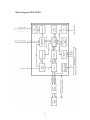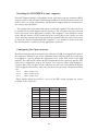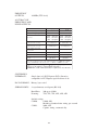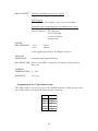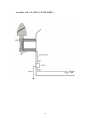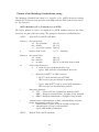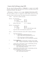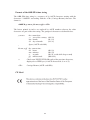
1
Technical Information
Operating Instructions
GPS170PEX
Contact Information
Meinberg Funkuhren GmbH & Co. KG
Lange Wand 9
D-31812 Bad Pyrmont
Phone:
Fax:
++49 52 81 - 9309-0
++49 52 81 - 9309-30
Internet: http://www.meinberg.de
Email: [email protected]
September 16, 2009
Table of Contents
Contact Information............................................................................. 2
Content of the USB stick ..................................................................... 5
General information............................................................................. 6
PCI Express (PCIe) .............................................................................. 7
Block diagram GPS170PEX ................................................................ 8
GPS170PEX features ........................................................................... 9
Time zone and daylight saving .................................................. 9
Asynchronous serial ports ........................................................ 10
Time capture inputs .................................................................. 10
Pulse and frequency outputs .................................................... 10
DCF77 emulation ..................................................................... 12
Connectors and LEDs in the rear slot cover ...................................... 13
Installing the GPS170PEX in your computer.................................... 14
Configuring the 9 pin connector .............................................. 14
Mounting the antenna ............................................................... 15
Powering up the system ........................................................... 15
Firmware updates............................................................................... 16
Replacing the lithium battery ............................................................ 16
Time codes ......................................................................................... 17
The time code generator ........................................................... 17
IRIG standard format ............................................................... 18
AFNOR-standard format .......................................................... 19
Assignment of CF Segment in IEEE1344 mode ...................... 20
Generated time codes ............................................................... 21
Selection of time code .................................................... 22
Table of Contents (continued)
Technical Specifications GPS170PEX .............................................. 23
Assignment of the 5 pin contact strip ...................................... 25
Technical specifications of antenna ......................................... 26
Assembly with CN-UB/E (CN-UB-280DC) ............................ 27
Format of the Meinberg Standard time string ......................... 28
Format of the Meinberg Capture String .................................. 29
Format of the SAT-time string ................................................ 30
Format of the NMEA 0183 string (RMC) ............................... 31
Format of the Uni Erlangen string (NTP) ................................ 32
Format of the ABB SPA time string ........................................ 34
CE label .............................................................................................. 34
Konformitätserklärung....................................................................... 35
Declaration of Conformity ................................................................ 35
4
Content of the USB stick
The USB stick contains a driver program that keeps the computer´s system time
synchronous to the board time. If the present delivered stick doesn’t include a driver
program for the operating system used, it can be downloaded from:
http://www.meinberg.de/english/sw/
On the USB stick there is a file called „readme.txt“, which helps installing the driver
correctly.
5
General information
The satellite clocks made by Meinberg have been designed to provide extremely
precise time to their users. The clocks have been developed for applications where
conventional radio clocks can´t meet the growing requirements in precision. High
precision available 24 hours a day around the whole world is the main feature of the
new system which receives its information from the satellites of the Global Positioning System.
The Global Positioning System (GPS) is a satellite-based radio-positioning, navigation, and time-transfer system. It was installed by the United States Department of
Defense and provides two levels of accuracy: The Standard Positioning Service
(SPS) and the Precise Positioning Service (PPS). While PPS is encrypted and only
available for authorized (military) users, SPS has been made available to the general
public.
GPS is based on accurately measuring the propagation time of signals transmitted
from satellites to the user´s receiver. A nominal constellation of 24 satellites together
with some active spares in six orbital planes 20000 km over ground provides a
minimum of four satellites to be in view 24 hours a day at every point of the globe.
Four satellites need to be received simultaneously if both receiver position (x, y, z)
and receiver clock offset from GPS system time must be computed. All the satellites
are monitored by control stations which determine the exact orbit parameters as well
as the clock offset of the satellites´ on-board atomic clocks. These parameters are
uploaded to the satellites and become part of a navigation message which is retransmitted by the satellites in order to pass that information to the user´s receiver.
The high precision orbit parameters of a satellite are called ephemeris parameters
whereas a reduced precision subset of the ephemeris parameters is called a satellite´s
almanac. While ephemeris parameters must be evaluated to compute the receiver´s
position and clock offset, almanac parameters are used to check which satellites are
in view from a given receiver position at a given time. Each satellite transmits its
own set of ephemeris parameters and almanac parameters of all existing satellites.
6
PCI Express (PCIe)
The main technical inovation of PCI Express is a serial data transmission compared
to the parallel interfaces of other computer bus systems like ISA, PCI and PCI-X.
PCI Express defines a serial point-to-point connection, the so-called Link:
The data transfer within a Link is done via Lanes, representing one wire pair for
sending and one wire pair for receiving data:
This design leads to a full duplex connection clocked with 2.5 GHz capable of
transfering a data volume of 250 MB/s per lane in each direction. Higher bandwith is
implemented by using multiple lanes silmutaneously. A PCI Express x16 slot for
example uses sixteen lanes providing a data volume of 4 GB/s. For comparison: when
using conventional PCI the maximum data transfer rate is 133 MB/s, PCI-X allows 1
GB/s but only in one direction respectively. A PCIe expansion board (x1 like
GPS170PEX for example) can always be used in slots with a higher lane width
(x4, x8, x16):
Slot
Card
x1
x1
Interoperability
x1
x4
x4
x8
x8
x1
x16
Yes
Yes
Yes
Yes
x4
x4
No
No
Yes
Yes
Yes
x8
x8
No
No
No
No
Yes
Yes
x16
No
No
No
No
No
No
Yes
One of the strong points of PCI Express is the 100% software compatibility to the
well known PCI bus, leading to a fast spreading. The computer and the operating
system are „seeing“ the more powerfull PCIe bus just as the convetional PCI bus
without any software update.
7
Block diagram GPS170PEX
8
GPS170PEX features
The satellite controlled clock GPS170PEX is designed as a standard height board for
computers with PCI Express interface. The data transfer to the computer is done by
using a single PCI Express Lane (x1 board). The rear slot cover integrates the antenna
connector, the modulated timecode, two status LEDs, and a 9 pin SUB-D male
connector. Monitoring software shipped with the board can be used to check the
clock's status and configure some operational parameters.
The antenna/converter unit is connected to the receiver by a 50 Ω coaxial cable
with length up to 300m (when using RG58 cable). Power is supplied to the unit DC
insulated across the antenna cable. Optionally, an over voltage protection and an
antenna distributor are available. The antenna distributor can be used to operate up to
4 Meinberg GPS receivers using a single antenna/converter unit.
The navigation message coming in from the satellites is decoded by satellite
clock's microprocessor in order to track the GPS system time with an accuracy of
better than 250nsec. Compensation of the RF signal´s propagation delay is done by
automatic determination of the receiver´s position on the globe. A correction value
computed from the satellites´ navigation messages increases the accuracy of the
board´s temperature compensated master oscillator (TCXO) to ±5•10-9 and automatically compensates the TCXO´s aging. The last recent value is restored from the nonvolatile memory at power-up. Optionally, the clock is also available with a higher
precision time base.
Time zone and daylight saving
GPS system time differs from the universal time scale (UTC) by the number of leap
seconds which have been inserted into the UTC time scale after GPS has been
initiated in 1980. The current number of leap seconds is part of the navigation
message supplied by the satellites, so the satellite clock´s internal real time is based
on UTC. Conversion to local time including handling of daylight saving year by year
can be done by the receiver´s microprocessor. For Germany, the local time zone is
UTC + 3600 sec for standard time and UTC + 7200 sec if daylight saving is in effect.
The clock's microprocessor determines the times for start and end of daylight
saving time by a simple algorithm e. g. for Germany:
Start of DST is on the first Sunday after March, 25th, at 2 o'clock standard time.
End of DST is on the first Sunday after October, 25th, at 3 o'clock daylight time.
The monitoring software shipped with the board can be used to configure the time
zone and daylight savings parameters easily. Switching to daylight saving time is
inhibited if for both start and end of daylight saving the parameters are exactly the
same.
The timecode (IRIG, AFNOR, IEEE) generated by GPS170PEX is available with
these settings or with UTC as reference. This can be set by the monitor program.
9
Asynchronous serial ports
Two asynchronous serial interfaces (RS232) called COM0 and COM1 are available
to the user. Only COM0 is available at the rear panel slot cover, COM1 must use
another submin-D connector which can optionally be connected to the 5 pin jumper
block on the board. The monitoring program can be used to configure the outputs. In
the default mode of operation, the serial outputs are disabled until the receiver has
synchronized after power-up. However, they can be configured to be enabled immediately after power-up. Transmission speed, framing and mode of operation can be
configured individually for each port. Both of the ports can be configured to transmit
either time strings (once per second, once per minute, or on request with ASCII ´?´
only), or to transmit capture strings (automatically when available, or on request).
The format of the output strings is ASCII, see the technical specifications at the end
of this document for details.
Time capture inputs
The board provides two time capture inputs called User Capture 0 and 1 (CAP0 and
CAP1) which can be mapped to pins at the 9 pin connector at the rear panel. These
inputs can be used to measure asynchronous time events. A falling TTL slope at one
of these inputs lets the microprocessor save the current real time in its capture buffer.
From the buffer, an ASCII string per capture event can be transmitted via COM1 or
displayed using the monitoring program. The capture buffer can hold more than 500
events, so either a burst of events with intervals down to less than 1.5 msec can be
recorded or a continuous stream of events at a lower rate depending on the transmission speed of COM1 can be measured. The format of the output string is described in
the technical specifications at the end of this document. If the capture buffer is full a
message "** capture buffer full" is transmitted, if the interval between two captures
is too short the warning "** capture overrun" is being sent via COM1.
Pulse and frequency outputs
The pulse generator of the satellite controlled clock GPS170PEX contains three
independent channels (PPO0, PPO1, PPO2). These TTL outputs can be mapped to
pins at the 9-pin connector at the rear slot cover by using a DIL switch. The pulse
generator is able to provide a multitude of different pulses, which are configured with
the monitor program. The active state of each channel is invertible, the pulse duration
settable between 10 msec and 10 sec in steps of 10 msec. In the default mode of
operation the pulse outputs are disabled until the receiver has synchronized after
power-up. However, the system can be configured to enable those outputs immediately after power-up.
10
The following modes can be configured for each channel independently:
Timer mode:
Three on- and off-times per day per channel programmable
Cyclic mode:
Generation of periodically repeated pulses.
A cycle time of two seconds would generate a pulse at
0:00:00, 0:00:02, 0:00:04 etc.
DCF77-Simulation
mode:
The corresponding output simulates the DCF77 time telegram.
The time marks are representing the local time as configured by the user.
Single Shot Mode: A single pulse of programmable length is generated once a day at a
programmable point of time
Per Sec.
Per Min.
Per Hr. modes:
Pulses each second, minute or hour
Status:
One of three status messages can be emitted:
‘position OK’: The output is switched on if the receiver was able to
compute its position
‘time sync’:
The output is switched on if the internal timing is
synchronous to the GPS-system
‘all sync’:
Logical AND of the above status messages.
The output is active if position is calculated AND the
timing is synchronized
Idle-mode:
The output is inactive
The default configuration for the pulse outputs is:
PPO0:
PPO1:
PPO2:
Pulse each second (PPS), active HIGH, pulse duration 200 msec
Pulse each minute (PPM), active HIGH, pulse duration 200 msec
DCF77 Simulation
A TTL level master frequency of 10 MHz is derived from the TCXO. By default,
this frequency is available only at the 5 pin contact strip of the board.
11
DCF77 emulation
The pulse outputs of GPS170PEX can provide time marks which are compatible with
the time marks spread by the German long wave transmitter DCF77. This long wave
transmitter installed in Mainflingen near Frankfurt/Germany transmits the reference
time of the Federal Republic of Germany: time of day, date of month and day of week
in BCD coded second pulses. Once every minute the complete time information is
transmitted. However, the clock generates time marks representing its local time as
configured by the user, including announcement of changes in daylight saving and
announcement of leap seconds. The coding scheme is given below:
Time marks start at the beginning of a new second. If a binary "0" is to be transmitted, the length of the corresponding time mark is 100 msec, if a binary "1" is
transmitted, the time mark has a length of 200 msec. The information on the current
date and time as well as some parity and status bits can be decoded from the time
marks of the 15th up to the 58th second every minute. The absence of any time mark
at the 59th second of a minute signals that a new minute will begin with the next time
mark.
12
Connectors and LEDs in the rear slot cover
GPS
antenna
LOCK
FAIL
modulated
timecode
BSL key
RxD
TxD
GND
The coaxial antenna connector, two status
LEDs and a 9 pin sub D connector can be
found in the rear slot cover. (see figure).
The upper, green LED (LOCK) is turned on
when after power-up the receiver has acquired at least four satellites and has computed
its position. In normal operation the receiver position is updated continuously as long
as at least four satellites can be received.
The lower, red LED (FAIL) is turned on
after power-up until the receiver has synchronized or if a severe error occurs during
operation.
The 9 pin sub D connector is wired to the
GPS170PEX's serial port COM0. Pin assignment can be seen from the figure beside.
This port can not be used as serial port for
the computer. Instead, it can be uses to send
out Meinberg's standard time string to an
external device.
A DIL switch on the board can be used to wire some TTL inputs
or outputs (0..5V) to some connector pins. In this case, absolute
care must be taken if another device is connected to the port,
because voltage levels of -12V through +12V (as commonly used
with RS-232 ports) at TTL inputs or outputs may damage the
radio clock.
Behind the little hole in the slot cover there is a push button (BSL) which is needed
if the clock's firmware shall be updated. See the chapter about firmware updates for
details.
13
Installing the GPS170PEX in your computer
Every PCI Express board is a plug&play board. After power-up, the computer's BIOS
assigns resources like I/O ports and interrupt numbers to the board, the user does not
need to take care of the assignments. The programs shipped with the board retrieve
the settings from the BIOS.
The computer has to be turned off and its case must be opened. The radio clock can
be installed in any PCI Express slot not used yet. The rear plane must be removed
before the board can be plugged in carefully. The computer´s case should be closed
again and the antenna can be connected to the coaxial plug at the clock's rear slot
cover. After the computer has been restarted, the monitor software can be run in order
to check the clock's configuration.The computer´s case should be closed again and
the antenna must be connected to the appropriate connector.
Configuring the 9 pin connector
By default only the signals needed for the serial port COM0 are mapped to the pins of
the connector. Whenever one of the additional signals shall be used, the signal must
be mapped to a pin by putting the appropriate lever of the DIL switch in the ON
position. The table below shows the pin assignments for the connector and the DIL
switch lever assigned to each of the signals. Care must be taken when mapping a
signal to Pin 1, Pin 4 or Pin 7 of the connector, because one of two different signals
can be mapped to these Pins. Only one switch may be put in the ON position in this
case:
Pin 1:
Pin 4:
Pin 7:
DIL 1 or DIL 8 ON
DIL 5 or DIL 10 ON
DIL 3 or DIL 7 ON
Those signals which do not have a lever of the DIL switch assigned are always
available at the connector:
D-SUB-Pin
Signal
Signal level
DIL-switch
1
VCC out
+5V
1
1
PPO0 (PPS) out
RS232
8
2
RxD in
RS232
-
3
TxD out
RS232
-
4
PPO1 (PPM) out
TTL
5
4
10MHz out
TTL
10
5
GND
-
-
6
CAP0 in
TTL
2
7
CAP1 in
TTL
3
7
IRIG DC out
TTL into 50 Ω
7
8
PPO0 (PPS) out
TTL
4
9
PPO2 (DCF) out
TTL
9
14
Mounting the antenna
The GPS satellites are not stationary but circle round the globe in a period of about 12
hours. They can only be received if no building is in the line-of-sight from the
antenna to the satellite, so the antenna/converter unit must be installed in a location
from which as much of the sky as possible can be seen. The best reception is given
when the antenna has a free view of 8° angular elevation above horizon. If this is not
possible the antenna should be installed with a mostly free view to the equator
because of the satellite courses which are located between latitudes of 55° North and
55° South.
If even this is not possible problems occur especially when at least four satellites
for positioning have to be found.
The unit can be mounted using a pole with a diameter up to 60 mm. A standard
coaxial cable with 50 Ω impedance (e.g. RG58C) should be used to connect the
antenna/converter unit to the receiver. Cable thinner than RG58 should be avoided
due to its higher DC resistance and RF attenuation. When using the optional antenna
diplexer the total length of one antenna line between antenna, diplexer and receiver
must not be longer than 300 m. If a cable with less attenuation is used its length may
be increased accordingly (e.g. 600 m with RG213).
Powering up the system
After the board has been mounted and the antenna has been connected, the system is
ready to operate. About 10 seconds after power-up the receiver´s TCXO operates
with the required accuracy. If the receiver finds valid almanac and ephemeris data in
its battery buffered memory and the receiver´s position has not changed significantly
since its last operation the receiver can find out which satellites are in view now.
Only a single satellite needs to be received to synchronize and generate output pulses,
so synchronization can be achieved at least one minute after power-up. After 20
minutes of operation the TCXO has achieved its final accuracy and the generated
frequencies are within the specified tolerances.
If the receiver position has changed by some hundred kilometers since last operation, the satellites´ real elevation and Doppler might not match those values expected
by the receiver thus forcing the receiver to start scanning for satellites. This mode is
called Warm Boot because the receiver can obtain ID numbers of existing satellites
from the valid almanac. When the receiver has found four satellites in view it can
update its new position and switch to normal operation. If the almanac has been lost
because the battery had been disconnected the receiver has to scan for a satellite and
read in the current almanacs. This mode is called Cold Boot. It takes 12 minutes until
the new almanac is complete and the system switches to Warm Boot mode scanning
for other satellites.
15
In the default mode of operation, neither pulse outputs nor the serial ports will be
enabled after power-up until synchronization has been achieved. However, it is
possible to configure some or all of those outputs to be enabled immediately after
power-up. If the system starts up in a new environment (e. g. receiver position has
changed or new power supply) it can take some minutes until the TCXO´s output
frequency has been adjusted. Up to that time accuracy of frequency drops to 10-8
reducing the accuracy of pulses to ±2µs.
Firmware updates
Whenever the on-board software must be upgraded or modified, the new firmware
can be downloaded to the internal flash memory via the radio clock's serial port
COM0. There is no need to open the computer case and insert a new EPROM.
If the button behind a hole in the rear slot cover is pressed for approximately 2
seconds, a bootstrap loader is activated and waits for instructions from the serial port
COM0. A loader program shipped together with the file containing the image of the
new firmware sends the new firmware from one of the computer's serial ports to the
clock's serial port COM0. The bootstrap loader does not depend on the contents of the
flash memory, so if the update procedure is interrupted, it can easily be repeated.
The contents of the program memory will not be modified until the loader program
has sent the command to erase the flash memory. So if the button has been pressed
accidentally, the system will be ready to operate again after the computer has been
turned off and then on again.
Replacing the lithium battery
The life time of the lithium battery on the board is at least 10 years. If the need arises
to replace the battery, the following should be noted:
ATTENTION!
There is a danger of explosion if the lithium battery is
installed incorrectly. Only identical batteries or batteries
recommended by the manufacturer must be used for replacement. The waste battery must be disposed as proposed by the manufacturer of the battery.
16
Time codes
The transmission of coded timing signals began to take on widespread importance
in the early 1950´s. Especially the US missile and space programs were the forces
behind the development of these time codes, which were used for the correlation of
data. The definition of time code formats was completely arbitrary and left to the
individual ideas of each design engineer. Hundreds of different time codes were
formed, some of which were standardized by the „Inter Range Instrumentation
Group“ (IRIG) in the early 60´s.
Except these „IRIG Time Codes“ other formats, like NASA36, XR3 or 2137, are
still in use. The board GPS170PEX however generates the IRIG-B, AFNOR NFS 87500 code as well as IEEE1344 code which is an IRIG-B123 coded extended by
information for time zone, leap second and date. If desired other formats are
available.
The time code generator
The board GPS170PEX generates modulated and un-modulated timecodes. Modulated signals are transmitting the information by varying the amplitude of a sine
wave carrier, un-modulated timecodes are transmitted by pulse duration modulation
of a DC-signal (TTL in case of GPS170PEX), see chapter „IRIG standard format“ for
details.
The sine wave carrier needed for modulated signals is generated in a digital way
by a programmable logic device on the board. The frequency of this signal is derived
from the main oscillator of GPS170PEX, which is disciplined by the GPS-system.
This leads to a sine wave carrier with high accuracy. Transmission of date is
synchronized by the PPS (pulse per second) derived from the GPS-system.
The modulated time code has an amplitude of 3Vpp (MARK) and 1Vpp (SPACE)
into 50 Ω. The number of MARK-amplitudes within ten periods of the carrier defines
the coding:
a) binary „0“
:
b) binary „1“
:
c) position-identifier :
2 MARK-amplitudes, 8 SPACE-amplitudes
5 MARK-amplitudes, 5 SPACE-amplitudes
8 MARK-amplitudes, 2 SPACE-amplitudes
The DC-signal has the following pulse durations accordingly:
a) binary „0“
:
b) binary „1“
:
c) position-identifier :
2 msec
5 msec
8 msec
17
IRIG standard format
18
AFNOR-standard format
19
Assignment of CF Segment in IEEE1344 mode
Bit No.
De signation
De scription
49
Position Identif ier P5
50
Year BCD encoded 1
51
Year BCD encoded 2
52
Year BCD encoded 4
53
Year BCD encoded 8
54
empty, always zero
55
Year BCD encoded 10
56
Year BCD encoded 20
57
Year BCD encoded 40
58
Year BCD encoded 80
59
Position Identifier P6
60
LSP - Leap Second Pending
set up to 59s before LS insertion
61
LS - Leap Second
1.)
62
DSP - Daylight Saving Pending
set up to 59s before daylight saving
changeover
63
DST - Daylight Saving Time
set during daylight saving time
64
Timezone Offset Sign
sign of TZ offset 0 = '+', 1 = '-'
65
TZ Offset binary encoded 1
66
TZ Offset binary encoded 2
67
TZ Offset binary encoded 4
68
TZ Offset binary encoded 8
69
Position Identifier P7
70
TZ Offset 0.5 hour
71
TFOM Time figure of merit
72
TFOM Time figure of merit
73
TFOM Time figure of merit
74
TFOM Time figure of merit
75
PARITY
low nibble of BCD encoded year
high nibble of BCD encoded year
0 = add leap second, 1 = delete leap second
Offset from IRIG time to UTC time.
Encoded IRIG time plus TZ Offset equals
UTC at all times !
set if additional half hour offset
time figure of merit represents approximated
clock error. 2.)
0x00 = clock locked
0x0F = clock failed
parity on all preceding bits incl. IRIG-B time
1.)
current firmware does not support deletion of leap seconds
2.)
TFOM is cleared, when clock is synchronized first after power up. see chapter Selection of generated timecode
20
Generated time codes
The board GPS170PEX generates modulated un-modulated (TTL into 50 Ω) timecodes, so that six different signals are available:
a) B002:
100pps, DC-signal, no carrier
BCD time of year
b) B122:
100pps, AM-sine wave signal, 1 kHz
BCD time of year
c) B003:
100pps, DC-signal, no carrier
BCD time of year, SBS time of day
d) B123:
100pps, AM-sine wave signal, 1 kHz
BCD time of year, SBS time of day
e) AFNOR:
Code according to NFS-87500, 100pps, AM-sine wave signal,
BCD time of year, complete date, SBS-Time of Day
1kHz
f) IEEE1344: Code. according to IEEE1344-1995, 100pps, AM-sine wave signal, 1kHz
BCD time of year, SBS time of day,
IEEE1344 expansion for date, time zone, daylight saving and leap second
in Control Functions Segment (CF)
see table „Assignment of CF Segment in IEEE1344 mode“
Modulated and un-modulated signals with the same coding (B002/B122 and B003/
B123) are always available simultaneously via the BNC- and the D-SUB-connector.
21
Selection of time code
The selection of timecode is done by the monitor software.
The un-modulated time code can be delivered as an active-high (default) or activelow signal by setting a jumper on the board GPS170PEX into the appropriate
position:
22
Technical Specifications GPS170PEX
RECEIVER:
Six channel C/A code receiver with external antenna/converter
unit
ANTENNA:
Antenna/converter unit with remote power supply
refer to chapter "Technical specifications of antenna"
POWER SUPPLY
FOR ANTENNA: 15 VDC, continuous short circuit potection, automatic recovery
Isolation voltage 1000 VDC
Provided via antenna cable
ANTENNA
INPUT:
Antenna circuit dc-insulated; dielectric strength: 1000V
Length of cable: refer to chapter "Mounting the Antenna"
TIME TO SYNCHRONIZATION:
one minute with known receiver position and valid almanac
12 minutes if invalid battery buffered memory
PULSE
OUTPUTS:
ACCURACY OF
PULSES:
TIME CAPTURE
INPUTS:
three programmable outputs, TTL level
Default settings:
active only ‚if sync‘
PPO0:
change of second (PPS)
pulse duration 200 msec
valid on rising edge
PPO1:
change of minute (PPM)
pulse duration 200 msec
valid on rising edge
PPO2:
DCF77 simulation
better than ±250 nsec after synchronization and 20 minutes of
operation
better than ±2 µsec during the first 20 minutes of operation
triggered on falling TTL slope
Interval of events: 1.5msec min.
Resolution: 100ns
23
FREQUENCY
OUTPUTS:
10 MHz (TTL level)
ACCURACY OF
FREQUENCY AND
PULSE OUTPUTS:
TCXO (standard)
short term stability (τ = 1 sec)
2 * 10
accuracy of PPS (pulse per second)
OCXO LQ (option)
-9
1 * 10
-9
< +/- 250 nsec
< +/- 250 nsec
1 Hz -60 dBc/Hz
10 Hz -90 dBc/Hz
100 Hz -120 dBc/Hz
1 kHz -130 dBc/Hz
1 Hz -60 dBc/Hz
10 Hz -90 dBc/Hz
100 Hz -120 dBc/Hz
1 kHz -130 dBc/Hz
accuracy free run, one day
+/- 1 * 10 -7
+/- 1 Hz (Note 1)
+/- 2 * 10 -8
+/- 0,2 Hz (Note 1)
accuracy free run, one year
+/- 1 * 10 -6
+/- 10 Hz (Note 1)
+/- 4 * 10 -7
+/- 4 Hz (Note 1)
phase noise
accuracy GPS-synchronous
averaged 24 h
+/- 1 * 10
accuracy of time free run, one day
+/- 8,6 msec
+/- 1,8 msec
accuracy of time free run, one year
+/- 32 sec
+/- 13 sec
-11
-6
temperature dependant drift,
free run
+/- 1 * 10
(-20...70°C)
+/- 1 * 10
-11
+/- 2 * 10 -7
(0...60°C)
Note 1:
The accuracy in Hertz is based on the standard frequency of 10 MHz. For example:
Accuracy of TCXO (free run one day) is +/- 1 * 10 E-7 * 10 MHz = +/- 1 Hz
The give n value s for the accuracy of fre que ncy and time (not short te rm
accuracy) are only valid for a constant ambie nt te mpe rature !
A minimum time of 24h of GPS-synchronicity is re quire d be fore fre e run starts.
SYSTEM BUS
INTERFACE:
Single lane (x1) PCI Express (PCIe) Interface
compatible to PCI Express specifications r1.0a
DATA FORMAT: Binary, byte serial
SERIAL PORTS:
2 asynchronous serial ports (RS-232)
Baud Rate:
Framing:
300 up to 19200
7N2, 7E1, 7E2, 8N1, 8N2, 8E1
default setting:
COM0:
19200, 8N1
Meinberg Standard time string, per second
COM1:
9600, 8N1
Capture string, automatically
24
IRIG-OUTPUTS:
Unbalanced modulated sine wave signal:
3Vpp (MARK), 1Vpp (SPACE) into 50 Ω
DCLS-signal:
TTL into 50 Ω, active-high or -low, selected by jumper
optionally optical output(instead of modulated sine wave):
optical power:
typ. 15µW
optical connector: ST-connector
for GI 50/125µm
or GI 62,5/125µm
gradient fiber
POWER
REQUIREMENT: +3.3 V:
+12 V :
70 mA
390 mA
power supplies provided by PCI Express interface
PHYSICAL
DIMENSION:
standard height expansion board
RF CONNECTOR: female coaxial BNC-connectors for antenna and modulated
time code
AMBIENT
TEMPERATURE: 0 ... 50°C
HUMIDITY:
85% max.
Assignment of the 5 pin contact strip
The contact strip can be used to access the 10 MHz frequency output and the serial
port COM1. Pin 5 is located near the board's bus connector:
Pin
Signal
1
10 MHz out
2
GND
3
RxD1 in
4
TxD1 out
5
GND
25
Technical specifications of antenna
ANTENNA:
dielectric patch antenna, 25 x 25mm
receive frequency: 1575.42 MHz
bandwidth:
9 MHz
CONVERTER:
local oscillator to converter frequency:
10 MHz
first IF frequency:
35.4 MHz
POWER
REQUIREMENTS: 12V ... 18V, @ 100mA (provided via antenna cable)
CONNECTOR:
coax type N, female
AMBIENT
TEMPERATURE: -40 ... +65°C
HOUSING:
ABS plastic case for outdoor installation (IP56)
PHYSICAL
DIMENSION:
26
Assembly with CN-UB/E (CN-UB-280DC)
27
Format of the Meinberg Standard time string
The Meinberg Standard time string is a sequence of 32 ASCII characters starting
with the STX (start-of-text) character and ending with the ETX (end-of-text) character. The format is:
<STX>D:dd.mm.yy;T:w;U:hh.mm.ss;uvxy<ETX>
The letters printed in italics are replaced by ASCII numbers whereas the other
characters are part of the time string. The groups of characters as defined below:
<STX>
Start-Of-Text (ASCII code 02h)
dd.mm.yy the current date:
dd day of month
(01..31)
mm month
(01..12)
yy year of the century (00..99)
w
the day of the week
(1..7, 1 = Monday)
hh.mm.ss
the current time:
hh hours
mm minutes
ss seconds
(00..23)
(00..59)
(00..59, or 60 while leap second)
uv
clock status characters:
u: ‘#’ clock has not synchronized after reset
‘ ‘ (space, 20h) clock has synchronized after reset
v:
different for DCF77 or GPS receivers:
‘*’ DCF77 clock currently runs on XTAL
GPS receiver has not checked its position
‘ ‘ (space, 20h) DCF77 clock is sync'd with transmitter
GPS receiver has determined its position
x
time zone indicator:
‘U’ UTC Universal Time Coordinated, formerly GMT
‘ ‘ MEZ European Standard Time, daylight saving disabled
‘S’ MESZ European Summertime, daylight saving enabled
y
announcement of discontinuity of time, enabled during last hour
before discontinuity comes in effect:
‘!’ announcement of start or end of daylight saving time
‘A’ announcement of leap second insertion
‘ ‘ (space, 20h) nothing announced
<ETX>
End-Of-Text (ASCII code 03h)
28
Format of the Meinberg Capture String
The Meinberg Capture string is a sequence of 31 ASCII characters terminated by a
CR/LF (Carriage Return/Line Feed) combination. The format is:
CHx_tt.mm.jj_hh:mm:ss.fffffff<CR><LF>
The letters printed in italics are replaced by ASCII numbers whereas the other
characters are part of the time string. The groups of characters as defined below:
x
_
0 or 1 corresponding on the number of the capture input
ASCII space 20h
dd.mm.yy the capture date:
dd day of month
(01..31)
mm month
(01..12)
yy year of the century (00..99)
hh:mm:ss.fffffff
hh
mm
ss
fffffff
<CR>
<LF>
the capture time:
hours
minutes
seconds
fractions of second,
(00..23)
(00..59)
(00..59, or 60 while leap second)
7 digits
Carriage Return, ASCII code 0Dh
Line Feed, ASCII code 0Ah
29
Format of the SAT-time string
The SAT-time string is a sequence of 29 ASCII characters starting with the STX
(start-of-text) character and ending with the ETX (end-of-text) character. The format
is:
<STX>dd.mm.yy/w/hh.mm.ssxxxxuv<ETX>
The letters printed in italics are replaced by ASCII numbers whereas the other
characters are part of the time string. The groups of characters as defined below:
<STX>
Start-Of-Text (ASCII code 02h)
dd.mm.yy the current date:
dd day of month
(01..31)
mm month
(01..12)
yy year of the century (00..99)
w
the day of the week
(1..7, 1 = Monday)
hh.mm.ss
the current time:
hh hours
mm minutes
ss seconds
(00..23)
(00..59)
(00..59, or 60 while leap second)
xxxx
time zone indicator:
‘UTC‘ Universal Time Coordinated, formerly GMT
‘MEZ‘ European Standard Time, daylight saving disabled
‘MESZ’ European Summertime, daylight saving enabled
u
clock status characters:
‘#’ clock has not synchronized after reset
‘ ‘ (space, 20h) clock has synchronized after reset
v
announcement of discontinuity of time, enabled during last hour
before discontinuity comes in effect:
‘!’ announcement of start or end of daylight saving time
‘ ‘ (space, 20h) nothing announced
<CR>
Carriage-return (ASCII code 0Dh)
<LF>
Line-feed (ASCII code 0Ah)
<ETX>
End-Of-Text (ASCII code 03h)
30
Format of the NMEA 0183 string (RMC)
The NMEA string is a sequence of 65 ASCII characters starting with the ‘$’ character
and ending with the characters CR (carriage return) and LF (line-feed). The format is:
$GPRMC,hhmmss.ss,A,bbbb.bb,n,lllll.ll,e,0.0,0.0,ddmmyy,0.0,a*hh<CR><LF>
The letters printed in italics are replaced by ASCII numbers or letters whereas the
other characters are part of the time string. The groups of characters as defined
below:
$
start character (ASCII-Code 24h)
hhmmss.ss
the current time:
hh hours
mm minutes
ss seconds
ss fractions of seconds
(00..23)
(00..59)
(00..59, or 60 while leap second)
(1/10 ; 1/100)
A
Status
(A = time data valid)
(V = time data not valid)
bbbb.bb
latitude of receiver position in degrees
leading signs are replaced by a space character (20h)
n
latitude, the following characters are possible:
‘N’ north of equator
‘S’ south d. equator
lllll.ll
longitude of receiver position in degrees
leading signs are replaced by a space character (20h)
e
longitude, the following characters are possible:
‘E’ east of Greenwich
‘W’ west of Greenwich
ddmmyy
the current date:
dd day of month
(01..31)
mm month
(01..12)
yy year of the century (00..99)
a
magnetic variation
hh
checksum (EXOR over all characters except ‘$’ and ‘*’)
<CR>
carriage-return; ASCII-Code 0Dh
<LF>
line-feed; ASCII-Code 0Ah
31
Format of the Uni Erlangen string (NTP)
The time string Uni Erlangen (NTP) of a GPS-clock is a sequence of 68 ASCII
characters starting with the STX (start-of-text) character and ending with the ETX
(end-of-text) character. The format is:
<STX>tt.mm.jj; w; hh:mm:ss; voo:oo; acdfg i; bbb.bbbbn llll.lllle hhhhm<ETX>
The letters printed in italics are replaced by ASCII numbers whereas the other
characters are part of the time string. The groups of characters as defined below:
<STX>
Start-Of-Text (ASCII code 02h)
dd.mm.yy the current date:
dd day of month
(01..31)
mm month
(01..12)
yy year of the century (00..99)
w
the day of the week
(1..7, 1 = Monday)
hh.mm.ss
the current time:
hh hours
mm minutes
ss seconds
(00..23)
(00..59)
(00..59, or 60 while leap second)
v
sign of the offset of local timezone related to UTC
oo:oo
offset of local timezone related to UTC in hours and minutes
ac
clock status characters:
a: ‘#’ clock has not synchronized after reset
‘ ‘ (space, 20h) clock has synchronized after reset
c:
‘*’ GPS receiver has not checked its position
‘ ‘ (space, 20h) GPS receiver has determined its position
d
time zone indicator:
‘S’ MESZ European Summertime, daylight saving enabled
‘ ‘ MEZ European Standard Time, daylight saving disabled
f
announcement of discontinuity of time, enabled during last hour
before discontinuity comes in effect:
‘!’ announcement of start or end of daylight saving time
‘ ‘ (space, 20h) nothing announced
g
announcement of discontinuity of time, enabled during last hour
before discontinuity comes in effect:
‘A’ announcement of leap second insertion
‘ ‘ (space, 20h) nothing announced
32
i
leap second insertion
‘L’ leap second is actually inserted
(active only in 60th sec.)
‘ ‘ (space, 20h) no leap second is inserted
bbb.bbbb latitude of receiver position in degrees
leading signs are replaced by a space character (20h)
n
latitude, the following characters are possible:
‘N’ north of equator
‘S’ south d. equator
llll.llll
longitude of receiver position in degrees
leading signs are replaced by a space character (20h)
e
longitude, the following characters are possible:
‘E’ east of Greenwich
‘W’ west of Greenwich
hhhh
altitude above sea level in meters
leading signs are replaced by a space character (20h)
<ETX>
End-Of-Text (ASCII-Code 03h)
33
Format of the ABB SPA time string
The ABB SPA time string is a sequence of 32 ASCII characters starting with the
characters ">900WD" and ending with the <CR> (Carriage Return) character. The
format is:
>900WD:yy-mm-tt_hh.mm;ss.fff:cc<CR>
The letters printed in italics are replaced by ASCII numbers whereas the other
characters are part of the time string. The groups of characters as defined below:
yy-mm-tt
the current date:
yy year of the century (00..99)
mm month
(01..12)
dd day of month
(01..31)
_
Space (ASCII code 20h)
hh.mm;ss.fff the current time:
hh hours
mm minutes
ss seconds
fff milliseconds
(00..23)
(00..59)
(00..59, or 60 while leap second)
(000..999)
cc
Check sum. EXCLUSIVE-OR result of the previous characters,
displayed as a HEX byte (2 ASCII characters 0..9 or A..F)
<CR>
Carriage Return (ASCII code 0Dh)
CE label
34
Konformitätserklärung
Declaration of Conformity
Hersteller
Meinberg Funkuhren GmbH & Co. KG
Lange Wand 9
D-31812 Bad Pyrmont
Manufacturer
erklärt in alleiniger Verantwortung, daß das Produkt
declares under its sole responsibility, that the product
Produktbezeichnung
Satellitenfunkuhr
Product Name
GPS170PEX
Modell / Typ
Model Designation
auf das sich diese Erklärung bezieht, mit den folgenden Normen übereinstimmt
to which this declaration relates is in conformity with the following standards
Funkprüfung nach ETSI EN 300 440 Ver. 1.4.1 vom 27.05.2008
Radio emission test in accordance with ETSI EN 300 440 Ver. 1.4.1 published 2008-05-27
Electromagnetic compatibility and Radio spectrum Matters (ERM);
Short range devices;
Radio equipment to be used in the 1 GHz
to 40 GHz frequency range
EMV-Prüfung nach ETSI EN 301 489-1 Ver. 1.8.1 vom 18.04.2008
EMC in accordance with ETSI EN 301 489-1 Ver. 1.8.1 published 2008-04-18
Electromagnetic compatibility and Radio spectrum Matters (ERM);
ElectroMagnetic Compatibility (EMC) standard for radio equipment
and services;
Part 1: Common technical requirements
Sicherheitsprüfung nach EN 60950-1:2006
Safety Test in accordance with EN 60950-1:2006
Information technology equipment — safety — Part 1: General
requirements
gemäß dem Gesetz über Funkanlagen und Telekommunikatiosendeinrichtungen
(FTEG) und den Richtlinien 99/5/EG (R&TTE), 89/336/EWG (Elektromagnetische
Verträglichkeit), 2006/95/EG (Niederspannungsrichtlinie) und 93/68/EWG (CE
Kennzeichnung) sowie deren Ergänzungen.
in accordance with the Radio and Telecommunications Terminal Equipment Act (FTEG) and following the
provisions of the directives 99/5/EC (R&TTE), 89/336/EEC (electromagnetic compatibility), 2006/95/EC
(low voltage directive) and 93/68/EEC (CE marking) and its amendments.
Bad Pyrmont, den 13.10.2008
35