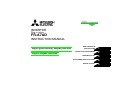
1
INVERTER
Plug-in option
FR-A7AD
INSTRUCTION MANUAL
High-speed analog output function
Digital output function
PRE-OPERATION
INSTRUCTIONS
1
INSTALLATION AND WIRING
2
PARAMETER LIST
3
HIGH-SPEED ANALOG OUTPUT
4
DIGITAL OUTPUT
5
Thank you for choosing this Mitsubishi Inverter plug-in option.
This Instruction Manual gives handling information and
precautions for use of this equipment. Incorrect handling might
cause an unexpected fault. Before using the equipment, please
read this manual carefully to use the equipment to its optimum.
Please forward this manual to the end user.
This section is specifically about
safety matters
Do not attempt to install, operate, maintain or inspect this
product until you have read through this Instruction Manual and
appended documents carefully and can use the equipment
correctly. Do not use this product until you have a full
knowledge of the equipment, safety information and
instructions.
In this Instruction Manual, the safety instruction levels are
classified into "WARNING" and "CAUTION".
WARNING
CAUTION
Incorrect
handling
may
cause
hazardous conditions, resulting in
death or severe injury.
Incorrect
handling
may
cause
hazardous conditions, resulting in
medium or slight injury, or may cause
only material damage.
CAUTION level may even lead to a serious
The
consequence according to conditions. Both instruction levels
must be followed because these are important to personal
safety.
SAFETY INSTRUCTIONS
1. Electric Shock Prevention
WARNING
• While power is ON or when the inverter is running, do not
open the front cover. You may get an electric shock.
• Do not run the inverter with the front cover or wiring cover
removed. Otherwise, you may access the exposed highvoltage terminals and charging part and get an electric shock.
• Even if power is OFF, do not remove the front cover except
for wiring or periodic inspection. You may accidentally touch
the charged inverter circuits and get an electric shock.
• Before wiring or inspection, power must be switched OFF. To
confirm that, LED indication of the operation panel must be
checked. (It must be OFF.) Any person who is involved in
wiring or inspection shall wait for at least 10 minutes after the
power supply has been switched OFF and check that there
are no residual voltage using a tester or the like. The
capacitor is charged with high voltage for some time after
power OFF, and it is dangerous.
• Any person who is involved in wiring or inspection of this
equipment shall be fully competent to do the work.
• The plug-in option must be installed before wiring. Otherwise,
you may get an electric shock or be injured.
• Do not touch the plug-in option or handle the cables with wet
hands. Otherwise you may get an electric shock.
• Do not subject the cables to scratches, excessive stress,
heavy loads or pinching. Otherwise you may get an electric
shock.
A-1
2. Injury Prevention
3) Usage
WARNING
CAUTION
• The voltage applied to each terminal must be the ones
specified in the Instruction Manual. Otherwise burst, damage,
etc. may occur.
• The cables must be connected to the correct terminals.
Otherwise burst, damage, etc. may occur.
• Polarity must be correct. Otherwise burst, damage, etc. may
occur.
• While power is ON or for some time after power-OFF, do not
touch the inverter as they will be extremely hot. Doing so can
cause burns.
3. Additional Instructions
Also the following points must be noted to prevent an accidental
failure, injury, electric shock, etc.
• Do not modify the equipment.
• Do not perform parts removal which is not instructed in this
manual. Doing so may lead to fault or damage of the inverter.
CAUTION
• When parameter clear or all parameter clear is performed, the
required parameters must be set again before starting
operations because all parameters return to the initial value.
• Static electricity in your body must be discharged before you
touch the product. Otherwise the product may be damaged.
4) Maintenance, inspection and parts replacement
1) Transportation and mounting
CAUTION
• Do not install or operate the plug-in option if it is damaged or
has parts missing.
• Do not stand or rest heavy objects on the product.
• The mounting orientation must be correct.
• Foreign conductive objects must be prevented from entering
the inverter. That includes screws and metal fragments or
other flammable substances such as oil.
2) Trial run
5) Disposal
CAUTION
• This inverter plug-in option must be treated as industrial
waste.
6) General instruction
CAUTION
• Before starting operation, each parameter must be confirmed
and adjusted. A failure to do so may cause some machines to
make unexpected motions.
A-2
CAUTION
• Do not test the equipment with a megger (measure insulation
resistance).
Many of the diagrams and drawings in this Instruction Manual
show the inverter without a cover or partially open for
explanation. Never operate the inverter in this manner. The
cover must be reinstalled and Instruction manual of the inverter
must be followed when operating the inverter.
— CONTENTS —
1
PRE-OPERATION INSTRUCTIONS
1.1
1.2
Inverter Model ....................................................................................................................................1
Unpacking and Product Confirmation .............................................................................................2
1.2.1
1.3
1.4
2
Product confirmation....................................................................................................................................... 2
Parts ....................................................................................................................................................3
Specifications.....................................................................................................................................4
INSTALLATION AND WIRING
2.1
2.2
2.3
1
5
Pre-Installation Instructions .............................................................................................................5
Installation Procedure .......................................................................................................................6
Wiring..................................................................................................................................................8
3
PARAMETER LIST
11
4
HIGH-SPEED ANALOG OUTPUT
12
4.1
4.2
4.3
Wiring Example ................................................................................................................................12
Terminals ..........................................................................................................................................13
Calibration procedure......................................................................................................................14
4.3.1
4.3.2
4.3.3
4.3.4
4.4
Calibration of voltmeter.................................................................................................................................14
Monitor setting ..............................................................................................................................................17
Scale setting ................................................................................................................................................. 21
High-speed analog output filter setting ......................................................................................................... 21
Instructions ......................................................................................................................................22
I
5
5.1
5.2
II
DIGITAL OUTPUT
23
Terminals ..........................................................................................................................................23
Output Signal List ............................................................................................................................24
1
1.1
PRE-OPERATION INSTRUCTIONS
Inverter Model
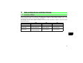
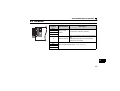
The inverter model numbers of 55K and 75K stated in this Instruction Manual differ according to -NA, -EC,
-CH(T) versions. Refer to the following correspondence table for each inverter model. (Refer to the
Instruction Manual of each inverter for the inverter model.)
For example, "for the 75K or higher" indicates "for the FR-A740-01440-NA or higher" in the case of FRA740 of NA version.
NA
FR-A720-55K
FR-A720-75K
FR-A740-55K
FR-A740-75K
FR-A720-02150-NA
FR-A720-02880-NA
FR-A740-01100-NA
(FR-A760-00840-NA)
FR-A740-01440-NA
(FR-A760-01040-NA)
EC
CH
⎯
⎯
⎯
⎯
FR-A740-01800-EC
FR-A740-55K-CHT
FR-A740-02160-EC
FR-A740-75K-CHT
1
1
PRE-OPERATION INSTRUCTIONS
1.2
Unpacking and Product Confirmation
Take the plug-in option out of the package, check the product name, and confirm that the product is as you
ordered and intact.
This product is a plug-in option for the FR-A700 series manufactured in December 2011 or later.
Check the SERIAL number specified on the inverter rating plate or package.
z SERIAL number check
Refer to Instruction manual of the inverter for the location of the rating plate.
Rating plate example
Symbol
1
Year
Z
Month
{{{{{{
Control number
SERIAL
The SERIAL consists of one symbol, two characters indicating production year and month,
and six characters indicating control number.
The last digit of the production year is indicated as the Year, and the Month is indicated by
1 to 9, X (October), Y (November), or Z (December).
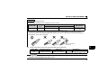
1.2.1
Product confirmation
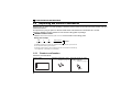
Check the enclosed items.
Plug-in option
Mounting screw (M3 × 6mm) Hex-head screw for option
......................................... 1 .............. 2 (Refer to page 6.) mounting (5.5mm)
............... 1 (Refer to page 6.)
5.5mm
2
PRE-OPERATION INSTRUCTIONS
1.3
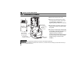
Parts
Terminal
block
Mounting
hole
Front view
Rear view
O
N
SW1
Mounting
hole
Switch for manufacturer
setting
Do not change from initiallyset status (OFF:
).
SW1
Connector
Connect to the inverter
option slot
(Refer to page 6)
Mounting hole
Terminal layout
5
5
5
5
5
5
DD3
1
DA2
DA3
DA4
DA5
DD0
DD1
DD2
3
PRE-OPERATION INSTRUCTIONS
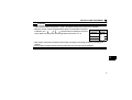
1.4 Specifications
(1) Output signals
High-speed analog output (across the terminal 5’s and the terminals DA2 to DA5), 0VDC to ±10VDC
(12-bit output resolution)
Digital output (across the terminal 5’s and the terminals DD0 to DD3), 3V to 6V for HI, 0V to 2V for LOW
(2) Output accuracy (reference value)
±10% of the full-scale output value.
Depends on the output signal type.
(3) Meters used
DC voltmeter
Wiring length
4
Full-scale ±10V (internal impedance 10kΩ or more)
Maximum 30m
2
INSTALLATION AND WIRING
2.1
Pre-Installation Instructions
Make sure that the input power of the inverter is off.
CAUTION
With input power on, do not install or remove the plug-in option. Otherwise, the inverter and
plug-in option may be damaged.
Static electricity in your body must be discharged before you touch the product. Otherwise the
product may be damaged.
2
5
INSTALLATION AND WIRING
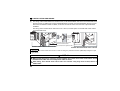
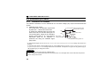
2.2
Installation Procedure
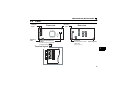
1)Remove the inverter front cover.
1)
2)Mount the hex-head screw for option
mounting into the inverter screw hole
(on earth plate). (size 5.5mm,
tightening torque 0.56N⋅m to 0.75N⋅m)
Screw hole for
option mounting
Inverter side
option
connector
3)
Screw hole for
option mounting
(on earth plate)
Hex-head screw
for option mounting
2)
4) Mounting
screws
3)Securely fit the connector of the plug-in
option to the inverter connector along
the guides.
4)Securely fix the both right and left sides
of the plug-in option to the inverter with
the accessory mounting screws.
(Tightening torque 0.33N⋅m to
0.40N⋅m) If the screw holes do not lineup, the connector may not have been
plugged snugly. Check for loose
plugging.
REMARKS
• Remove a plug-in option after removing two screws on both left and right sides.
(When the plug-in option is mounted in the connector 3, it is easier to remove the plug-in option after removing a
control circuit terminal block.)
6
INSTALLATION AND WIRING
CAUTION
•
•
Only one type of option per inverter may be used. When two or more options are mounted, priority is in
order of inverter option connectors 1, 2 and 3, the options having lower priority are inoperative.
When the inverter cannot recognize that the option is mounted due to improper
Mounting
Error
installation, etc., "
to
" (option alarm) are displayed. The errors
Position
Display
shown differ according to the mounting positions (connectors 1, 2, 3).
Connector 1
Connector 2
Connector 3
•
•
Take caution not to drop a hex-head screw for option mounting or mounting screw during mounting and
removal.
Pull the option straight out when removing. Otherwise, the connector may be damaged.
2
7
INSTALLATION AND WIRING
2.3
Wiring
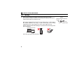
(1) Untwist the twisted pair shielded cables after stripping its sheath.
Also, perform protective treatment of the shield to ensure that it will not
make contact with the conductive area.
Strip off the sheath about the size as in the below figure. If the length of
the sheath pealed is too long, a short circuit may occur among
neighboring wires. If the length is too short, wires might come off.
Wire the stripped cable after twisting it to prevent it from becoming loose.
(Do not solder it.)
Cable stripping length
5mm
Use a bar type terminal as required.
8
Shield
(perform protective treatment)
Sheath
Twisted pair
shielded cable
INSTALLATION AND WIRING
REMARKS
• Information on blade terminals
Commercially available product examples (as of Jan. 2010)
Terminal
Screw Size
Wire Size
(mm2)
M2
0.3, 0.5
Blade Terminal Model
With insulation sleeve Without insulation sleeve
AI 0,5-6WH
Manufacturer
Phoenix Contact
Co.,Ltd.
A 0,5-6
Blade terminal crimping tool: CRIMPFOX 6T-F/6 (Phoenix Contact Co., Ltd.)
Insert wires to a blade terminal, and check that the wires come out for about 0 to 0.5 mm from a sleeve.
Check the condition of the blade terminal after crimping. Do not use a blade terminal of which the crimping is
inappropriate, or the face is damaged.
ell
Unstranded
wires
ire
W
Sh
Sl
e
ev
m
.5m
o0
t
0
e
Damaged
Crumpled tip
Wires are not inserted
into the shell
2
(2) Loosen the terminal screw and insert the cable into the terminal.
Screw Size
M2
Tightening Torque
0.22N⋅m to 0.25N⋅m
Cable Size
Screwdriver
0.3mm2 to 0.75mm2
Small
flat-blade screwdriver
(Tip thickness: 0.4mm/tip width: 2.5mm )
CAUTION
• Undertightening can cause cable disconnection or malfunction. Overtightening can cause a short circuit or
malfunction due to damage to the screw or unit.
9
INSTALLATION AND WIRING
(3) For wiring of the inverter which has one front cover, route wires between the control circuit terminal block
and front cover. If cables can not be routed between the control circuit terminal block and front cover
due to the increased number of cables, remove a hook of the front cover and use a space become
available.
For wiring of the inverter which has front cover 1 and 2, use the space on the left side of the control
circuit terminal block.
Cut off
with a
nipper,
etc.
Front cover
Cut off a hook on the inverter
front cover side surface.
(Cut off so that no portion is left.)
Inverter which has one front cover
Front cover 1
Front cover 2
Control circuit
terminal block
Inverter which has front cover 1 and 2
REMARKS
• When the hook of the inverter front cover is cut off for wiring, the protective structure (JEM1030) changes to open
type (IP00).
CAUTION
When performing wiring using the space between the inverter front cover and control circuit
terminal block, take care not to subject the cable to stress.
After wiring, wire offcuts must not be left in the inverter. They may cause a fault, failure or
malfunction.
10
3
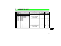
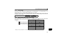
PARAMETER LIST
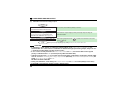
When the FR-A7AD is mounted on the inverter, the following parameters are extended.
Digital output
High-speed analog output
Parameter
Number
Name
525
DA2 output selection
527
DA3 output selection
529
DA4 output selection
531
DA5 output selection
526
DA2 scale
528
DA3 scale
530
DA4 scale
532
DA5 scale
537
High-speed DA output filter
533
DD0 output selection
534
DD1 output selection
535
DD2 output selection
536
DD3 output selection
Setting Range
Minimum
Setting
Increments
Initial
Value
Refer
to
Page
1 to 3, 5 to 14, 17 to 18, 21, 24,
32 to 34, 36, 46, 50, 52, 53,
201 to 211, 230 to 232,
235 to 238, 255
1
255
17
1 to 400%
1%
100%
21
0 to 8888, 9999
1
9999
21
0 to 8, 10 to 20, 25 to 28,
30 to 36, 39, 41 to 47, 55, 64, 70,
83 to 95, 97 to 99, 100 to 111,
120 to 136, 255
1
255
24
3
11
4
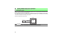
HIGH-SPEED ANALOG OUTPUT
4.1 Wiring Example
Use Pr. 525 to Pr. 532 and Pr. 537 to output analog signals, such as output frequency and output current,
from the voltage output terminals (DA2 to DA5).
The voltage output terminals are updated more frequently than the terminals FM/AM/CA* of the inverter.
Thus, high-speed monitoring is available with these terminals. (Refer to page 19 for high-speed monitoring.)
* Terminals provided differ according to the inverter.
Connect the voltmeter as shown below:
Inverter
(Voltmeter)
FR-A7AD
+
-
0 to
10VDC
DA2 to DA5
5
CAUTION
• The wiring length between the FR-A7AD and the voltmeter should be 30m maximum.
12
HIGH-SPEED ANALOG OUTPUT
4.2 Terminals
5
5
5
5
5
5
DD3
DA2
DA3
DA4
DA5
DD0
DD1
DD2
Terminal
Symbol
DA2
DA3
DA4
DA5
5
DD0
DD1
DD2
DD3
Terminal Name
Voltage output
terminal
Description
Connect a DC voltmeter (±10VDC).
Common terminals for DA2 to DA5 and DD0 to
DD3.
Common terminal
These terminal 5’s are connected with the
terminal 5 of the inverter.
Used for digital output function. (Refer to page 23 )
4
13
HIGH-SPEED ANALOG OUTPUT
4.3 Calibration procedure
4.3.1
Calibration of voltmeter
If a voltmeter is deviated, it can be calibrated at 0V or full-scale voltage (10V) output of the terminals DA2
to DA5.
(1) Calibration at 0V output
Turning ON the X83 turns ON the Y83.
In the initial status, 0V calibration is performed
At least 20ms required
at power OFF → ON and at inverter reset.
ON
X83
To perform 0V calibration after the power has
Hold for at least 100ms
been turned ON, turn ON the X83 signal. To
ON
Y83
use the X83 signal, assign the 0V calibration
request signal (X83) to an input terminal High-speed
beforehand. While the 0V calibration is analog output
During calibration,
performed, the during 0V calibration signal
the high-speed analog output is 0.
(Y83) is ON.
* To input the X83 signal, set "83" in one of Pr.178 to Pr.189 (input terminal function selection) to assign the function to a
terminal.
To output the Y83 signal, set "83 (positive logic)" or "183 (negative logic)" in one of Pr.190 to Pr.196 or Pr.533 to Pr.536
(output terminal function selection) to assign the function to a terminal. To output the LF signal, set "98 (positive logic) or
198 (negative logic)" to assign the function.
REMARKS
• The alarm signal (LF) turns ON if 0V calibration fails.
• Output signals are undetermined while the Y83 signal is ON. The Y83 signal does not turn ON while the power is
ON or during inverter reset.
14
HIGH-SPEED ANALOG OUTPUT
CAUTION
• Keep the X83 signal ON for 20ms or longer. Otherwise, calibration may not be performed.
• When the X83 signal is assigned, 0V calibration is not performed at power ON and at inverter reset. If power
is turned OFF while the X83 is assigned, a 0V-calibrated value returns back to the logical value because the
inverter does not save such calibrated values.
• Changing a terminal assignment using Pr.178 to Pr.189 (input terminal function selection) and Pr.190 to Pr.196 or
Pr.533 to Pr.536 (output terminal function selection) may affect other functions. Set parameters after confirming the
function of each terminal.
4
15
HIGH-SPEED ANALOG OUTPUT
(2) Calibration at full-scale voltage output
START
Connect a DC voltmeter across terminal 5
and a terminal between DA2 and DA5.
At this time, check that the polarity is correct
Set "21 (reference voltage output)" in Pr.525,
Pr.527, Pr.529, or Pr.531 according to the
terminal to be calibrated. (Refer to page 17.)
The maximum output voltage (10VDC) is actually output to swing the
voltmeter needle.
Use Pr. 900 to perform adjustment, then set.
END
After making adjustment with
press
to set.
to deflect the voltmeter to full-scale
Specify the output signal type by setting Pr.525, Pr.527, Pr.529, or Pr.531.
CAUTION
• If calibration is made without "21 (reference voltage output)" set in Pr.525, Pr.527, Pr.529, or Pr.531, the
terminal FM or CA* of the inverter is calibrated. To calibrate the high-speed analog output, always set "21".
(* Terminals provided differ according to the inverter.)
• If "21" is set in several parameters of Pr.525, Pr.527, Pr.529, and Pr.531, the terminal that has the highest
priority is calibrated with Pr.900. (Terminal priority: DA2>DA3>DA4>DA5)
• Calibration priority with Pr.900 is as follow when using FR-A7AY or FR-A7AZ in combination with FR-A7AD
and "21" is set in Pr.310 Analog meter voltage output selection (FR-A7AY), Pr.838 DA1 terminal function selection (FRA7AZ), Pr.525, Pr.527, Pr.529, and Pr.531.
FR-A7AY>FR-A7AZ>FR-A7AD
• During 10V calibration, scale settings of Pr.526, Pr.528, Pr.530, and Pr.532 are invalid (always set to 100%).
• If FR-A7AD is remounted on another inverter, calibrate again.
16
HIGH-SPEED ANALOG OUTPUT
4.3.2
Monitor setting
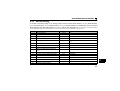
To output a monitored result as an analog output, set the values shown below in Pr.525 (terminal DA2),
Pr.527 (terminal DA3), Pr.529 (terminal DA4), or Pr.531 (terminal DA5). For details about the monitored
items selected with the setting values "1 to 53", refer to the description of Pr.54 FM/CA terminal function
selection and Pr.158 AM terminal function selection in the Instruction Manual of the inverter.
Setting
Types of Monitor
1*1
2
3
5
Output frequency
Output current
Output voltage
Frequency setting value
6*1
Running speed
7*3
8
9
Motor torque
Converter output voltage
Regenerative brake duty
Electric thermal relay function load
factor
Output current peak value
Converter output voltage peak value
Input power
Output power
Load meter
Motor excitation current
10
11
12
13
14
17*3
18
21
Reference voltage output
Increments
0.01Hz
0.01A/0.1A*2
0.1V
0.01Hz
Full Scale Value
Pr.55
Pr.56
400V/800V
Pr.55
0.1%
0.1V
0.1%
The value converted with the Pr. 37 value from
Pr. 55.
Pr.866
400V/800V
Pr.70
0.1%
100%
1(r/min)
0.01A/0.1A*2
0.1V
0.01kW/0.1kW*2
0.01kW/0.1kW*2
0.1%
0.01A/0.1A*2
—
Pr.56
400V/800V
Rated inverter power × 2
Rated inverter power × 2
Pr.866
Pr.56
—
4
17
HIGH-SPEED ANALOG OUTPUT
Setting
24
32*3
33*3
34*4
36*4
46*5
*1
*2
*3
*4
*5
18
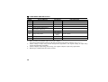
Types of Monitor
Motor load factor
Torque command
Torque current command
Motor output
Torque monitor (power driving/
regeneration switchover)
Motor temperature
50
Energy saving effect
52
53
PID set point
PID measured value
Increments
0.1%
0.1%
0.1%
0.01kW/0.1kW*2
Full Scale Value
200%
Pr.866
Pr.866
Rated motor current
—
Pr.866
1°C
Pr.751
Changeable by
parameter
Inverter capacity
setting.
0.1%
100%
0.1%
100%
Outputs 0V to +10V during forward rotation, and 0V to -10V during reverse rotation.
Differs according to capacities. (55K or lower/75K or higher)
The inverter model numbers of 55K and 75K differ according to -NA and -EC versions. (Refer to page 1.)
Positive voltage is output during forward driving/reverse regeneration, and negative voltage is output during
reverse driving/forward regeneration.
Positive voltage is output during power driving, and negative voltage is output during regeneration.
Monitoring is available when FR-A7AZ is mounted.
HIGH-SPEED ANALOG OUTPUT
Setting
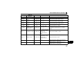
201*8
202*8, *9
203*8, *9
204*8, *9
205*8
206*8
Types of
Monitor
Increments
0.01Hz
Full Scale Value
Description
Output frequency
U-phase output
current
V-phase output
current
W-phase output
current
Converter output
voltage
0.01A/0.1A*6 Pr.56 × √2
Displays the U-phase output current.
0.01A/0.1A *6 Pr.56 × √2
Displays the V-phase output current.
0.01A/0.1A *6 Pr.56 × √2
Displays the W-phase output current.
Output current of
three phases
0.01A/0.1A *6 Pr.56 × √2
0.1V
207*8, *9, *10 Excitation current 0.01A/0.1A *6
208*8, *9, *10 Torque current
0.01A/0.1A *6
209
Terminal 2
0.1%
210
Terminal 4
0.1%
Pr.55
200V class: 400V
400V class: 800V
Displays the inverter output frequency.
Displays the DC bus voltage.
Displays the maximum output current among
the absolute currents in the U, V, and W
phases.
V/F control, Advanced
magnetic flux vector
control: Pr.56
Displays the excitation current
Other than above:
300%
V/F control, Advanced
magnetic flux vector
control: Pr.56
Displays the torque current.
Other than above:
Pr.866
Displays the input voltage to the terminal 2
100%
(displays 100% for 10V (fixed))
Displays the input voltage to the terminal 4
100%
(displays 100% for 10V (fixed))
4
19
HIGH-SPEED ANALOG OUTPUT
Setting
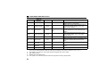
211 *9
Types of
Monitor
Terminal 1
Increments
Full Scale Value
0.1%
100%
230*7, *8, *9
Output frequency
0.01Hz
Pr.55
231*7, *8, *9
Motor speed
1r/min
Pr.55 (converted to
r/min)
232*7, *8, *9
Speed command
1r/min
Pr.55
235*7, *8, *9
Torque command
0.1%
Pr.866
0.1%
Pr.866
0.1%
300%
0.1%
Pr.866
236*7, *8, *9, *10 Motor torque
237*7, *8, *9
238*7, *8, *9
255
*6
Excitation current
command
Torque current
command
No monitor
—
—
Description
Displays the input voltage to the terminal 1
(displays 100% for 10V (fixed))
Displays the inverter output frequency (0V to
+10V during forward rotation, 0V to -10V
during reverse rotation)
Displays the motor speed (0V to +10V during
forward rotation, 0V to -10V during reverse
rotation)
Displays the speed command (0V to +10V
during forward rotation, 0V to -10V during
reverse rotation)
Displays the torque command.
Displays the motor torque in percentage on the
assumption that the rated motor torque is
100%.
Displays the excitation current command.
Displays the commanded current for the
torque.
—
Differs according to capacities. (55K or lower/75K or higher)
The inverter model numbers of 55K and 75K differ according to -NA and -EC versions. (Refer to page 1.)
*7 The output is "0" under V/F control and Advanced magnetic flux vector control.
*8 High-speed monitor.
*9 Monitor with a plus/minus sign.
*10 The output is "0" under DC injection brake and magnetic flux decay output shutoff.
20
HIGH-SPEED ANALOG OUTPUT
4.3.3
Scale setting
The scale of output voltage can be adjusted with Pr.526 (terminal DA2), Pr.528 (terminal DA3), Pr.530
(terminal DA4), and Pr.532 (terminal DA5). (Setting range: 1% to 400%)
Use this function when you need to change the scale of the monitor because the full scale value is not
changeable. Output voltages from the terminals DA2 to DA5 are output according to the scale ratios
(Pr.526, Pr.528, Pr.530, Pr.532).
Output voltage = 10V ×
4.3.4
Monitor value
×
Full scale value
100%
Scale ratio
High-speed analog output filter setting
Set a value between "0 and 8" in each digit of Pr.537 to activate filters for the high-speed analog output
terminals DA2 to DA5. Adjust the filter setting when a terminal output is unstable.
Filter Setting
Time Constant
Example)
Pr.537 = 0123
DA2 filter setting value (6ms)
DA3 filter setting value (4ms)
DA4 filter setting value (2ms)
DA5 filter setting value (0ms)
0
1
2
3
4
5
6
7
8
9999 (initial value)*
0ms
2ms
4ms
6ms
8ms
10ms
12ms
14ms
16ms
No filter for all terminals
4
* Setting "9" to only one digit of Pr.537 is not possible. The setting value "9" must be set to all four digits.
21
HIGH-SPEED ANALOG OUTPUT
4.4 Instructions
(1) A voltmeter having smaller internal impedance than the value indicated in the Specifications (page 4)
may not deflect to full-scale and may not be calibrated.
(2) To calibrate a voltmeter, of which full scale is less than 10VDC, disconnect the voltmeter first. Then,
set terminal DA2 to DA5 outputs to the smallest values (set scale ratios to Pr.526, Pr.528, Pr.530, and
Pr.532) according the voltmeter, and reconnect the voltmeter.
CAUTION
At the time of shipping, full-scale output is set to 10VDC. If a voltmeter, of which full scale is
less than 10VDC, is calibrated with the default setting, the voltmeter may be damaged. Make
sure to set the scale ratios according to the voltmeter.
(3) When an option error (
22
to
) occurs, all outputs are off.
5
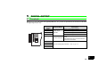
DIGITAL OUTPUT
5.1 Terminals
Use Pr.533 to Pr.536 to output the signals (RUN, SU, etc.), which are provided in the inverter as standard,
as digital signals (0V, 5V).
Terminal
Symbol
Terminal Name
DD0
5
5
5
5
5
5
DD3
DA2
DA3
DA4
DA5
DD0
DD1
DD2
DD1
DD2
DD3
5
Digital output
terminals
Common terminal
Description
Use Pr. 533 to assign functions.
Use Pr. 534 to assign functions.
Use Pr. 535 to assign functions.
Use Pr. 536 to assign functions.
Common terminals for DD0 to DD3 and DA2
to DA5.
These terminal 5’s are connected with the
terminal 5 of the inverter.
DA2
DA3
DA4
Used for analog output function. (Refer to page 12)
DA5
23
5
DIGITAL OUTPUT
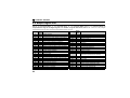
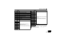
5.2 Output Signal List
Use Pr.533 (terminal DD0), Pr. 534 (terminal DD1), Pr. 535 (terminal DD2), and Pr. 536 (terminal DD3) to
output different signals as digital signals. For details of signal definitions, refer to Pr. 190 to Pr. 196 (Output
terminal function selection) of Instruction manual of the inverter.
Setting
0
1
2
3
4
5
6
7
8
10
11
12
13
14
15
16
17
18
19
20
25
26
27
28
24
Signal
Name
RUN
SU
IPF
OL
FU
FU2
FU3
RBP
THP
PU
RY
Y12
Y13
FDN
FUP
RL
MC1
MC2
MC3
BOF
FAN
FIN
ORA
ORM
Function
Setting
Inverter running
Up to frequency
Instantaneous power failure/undervoltage
Overload alarm
Output frequency detection
Second output frequency detection
Third output frequency detection
Regenerative brake pre-alarm
Electronic thermal relay function pre-alarm
PU operation mode
Inverter operation ready
Output current detection
Zero current detection
PID lower limit
PID upper limit
PID forward/reverse rotation output
Commercial power-supply switchover MC1
Commercial power-supply switchover MC2
Commercial power-supply switchover MC3
Brake opening request
Fan fault output
Heatsink overheat pre-alarm
Orientation in-position
Orientation error
30
31
32
33
34
35
36
39
41
42
43
44
45
Signal
Name
Y30
Y31
Y32
RY2
LS
TU
Y36
Y39
FB
FB2
FB3
RUN2
RUN3
46
Y46
47
55
64
70
83
84
85
86
87
PID
Y55
Y64
SLEEP
Y83
RDY
Y85
Y86
Y87
Function
Forward rotation output
Reverse rotation output
Regenerative status output
Operation ready 2
Low speed output
Torque detection
In-position
Start time tuning completion
Speed detection
Second speed detection
Third speed detection
Inverter running 2
Inverter running and start command is on
During deceleration due to instantaneous
power failure (retained until release)
During PID control activated
Motor temperature detection
During retry
During PID output suspension
During 0V calibration
Position control preparation ready
DC current feeding
Control circuit capacitor life
Main circuit capacitor life
DIGITAL OUTPUT
Setting
88
89
90
91
92
93
94
95
97
98
99
Signal
Name
Y88
Y89
Y90
Y91
Y92
Y93
ALM2
Y95
ER
LF
ALM
Function
Cooling fan life
Inrush current limit circuit life
Life alarm
Fault output 3 (power off signal)
Energy saving average value updated timing
Current average monitor signal
Fault output 2
Maintenance timer signal
Alarm output 2
Alarm output
Fault output
.
Setting
100
101
102
103
104
105
106
107
108
109
110
111
Terminal
Name
STF
STR
RL
RM
RH
RT
AU
JOG
CS
MRS
STOP
RES
Function
Outputs the different input terminal
statuses of the inverter.
(Refer to the Instruction Manual of the
inverter for the details of the terminals.)
Setting
120
121
122
123
124
125
126
127
128
129
130
131
132
133
134
135
136
255
Terminal
Name
X0
X1
X2
X3
X4
X5
X6
X7
X8
X9
X10
X11
X12
X13
X14
X15
DY
—
Function
Outputs the different terminal statuses of
FR-A7AX.
(Refer to the Instruction Manual of FRA7AX for the details of the terminals.)
No function
REMARKS
• When an option error (
all outputs are tuned off.
to
) occurs,
25
5
MEMO
26
MEMO
27
REVISIONS
*The manual number is given on the bottom left of the back cover.
Print Date
Nov. 2011
28
*Manual Number
IB(NA)-0600475ENG-A First edition
IB(NA)-0600475ENG-A
Revision
INVERTER
HEAD OFFICE: TOKYO BUILDING 2-7-3, MARUNOUCHI, CHIYODA-KU, TOKYO 100-8310, JAPAN
IB(NA)-0600475ENG-A (1111) MEE
Printed in Japan
Specifications subject to change without notice.