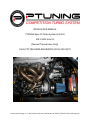
1
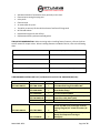
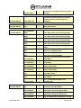
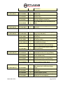
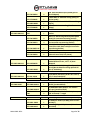
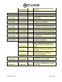
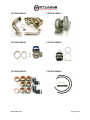
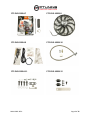
INSTALLATION MANUAL PTUNING Spec-SS Turbo System (Full Kit) 2011-2012 Scion tC (Manual Transmission Only) Part#: PTP-TBK-10004-RED/BLK/POL (2011-2012 M/T) Performance Tuning, Inc. | 9432 Center Point Lane | Manassas, VA 20110 | 703-257-1728 | Ptuning.com READ THIS FIRST: Please read the entire installation manual before proceeding. Engine and/or turbocharger damage may occur if any component within these instructions is improperly installed. This installation should only be performed by a trained specialist who is familiar with the automobile’s mechanical, electrical and fuel management system. Performance Tuning, Inc (PTUNING) or any of its distributors cannot be held responsible for damages as a result of negligent or improper installation. This turbocharger system can be installed using common tools and automotive procedures. If in doubt, please contact PTUNING’s technical support staff at 703-257-1728, between the hours of 10:00AM and 5:00PM EST, Monday through Friday. Remove the turbocharger system from its packaging and inspect for any obvious physical damage. All kit components are thoroughly inspected and carefully packaged prior to shipment from the factory. If any shipping damage is evident, contact your supplier and request that they process a claim with the shipper involved. Be sure to review the parts list on page three to verify that you have all necessary system components to proceed. If any components in the parts list are missing, contact PTUNING’s customer service staff. Although this turbocharger system has been designed to retain many of the factory emissions controls, it is not CARB legal in California and therefore recommended for “off road” use only. In other states, check local laws regarding aftermarket modification to emission controlled vehicles. The use of premium grade gasoline (93 octane or higher) is required with this kit. We recommend gapping the factory spark plugs between 0.024”-0.026”. Although this turbocharger system (full kit) includes a pre-loaded, professionally tuned based map, final calibration of the base map for your specific vehicle and local atmospheric conditions must be performed by a professional tuner before attempting to drive the vehicle under boost. The information contained in this publication was accurate and in effect at the time the publication was approved for printing and is subject to change without notice or liability. PTUNING reserves the right to revise the information presented herein or to discontinue the production of parts described at any time. SAFETY REQUIREMENTS: It is recommended to follow these precautions. Always wear safety glasses & gloves. Turn the ignition switch to the OFF position & disconnect the battery. Always use properly rated jack stands when working under the vehicle. Prevent unexpected vehicle movement by using wheel chocks and/or parking brake. Operate the vehicle only in well ventilated areas. Do not smoke or use flammable items near or around the vehicle’s fuel system. Keep hands, clothing and other objects away from moving parts when engine is running. SUPPLIES: It is recommended to have the following items before beginning installation. Scion factory service manual, for your model year Scion TC. A large table or bench, and plenty of adjacent available workspace. MAN-10001-REV1 Page 2 of 76 Standard selection of automotive tools, primarily metric sizes. Electrical wire cutting/crimping tool. Utility knife Electrical tape. An assortment of zip ties. The ability to securely lift the vehicle at least a few feet off the ground. NPT thread sealant. Replacement engine oil and oil filter. Replacement factory exhaust manifold gasket. TORQUE RECOMMENDATION: When removing and re-installing factory fasteners, refer to the Scion service manual for torque values. When installing fasteners included in this kit, refer to the following chart: FASTENER SIZE TORQUE (FOOT POUND) 6mm 12 8mm 22 10mm 30 NPT fittings 2-3 turn past finger tight TURBOCHARGER SYSTEM PARTS LIST (Included with Part# PTP-TBK-10004-RED/BLK/POL): PACKAGE PART #: PART #: PTP-PKG-10004-1 PTP-TBM-10004 1 PTP-DNP-10004 PTP-GSK-90010 1 1 PTP-FAS-90050-25 PTP-WGD-10004 4 1 PTP-PKG-10004-2 MAN-10001-REV1 Qty/Kit PTP-TRG-90000 1 PTP-FTG-90032 1 DESCRIPTION PTUNING Full 304SS Equal-Length Competition Turbo Manifold Flanged for 40mm WG 2.5" 4-bolt 304SS Downpipe with OEM-Style Donut Gasket Flange 2.5" Donut Gasket G20B-S M8 x 1.25 x 25mm Flanged Hex Head Cap Screw (Class 10.9, Black-oxide) 1.75" x 12" 304SS Dump Tube Garrett T3/TO4E T3 57 Trim Stage 3 turbine housing, flange w/2.5" 4-bolt T31 outlet (.82 A/R) 1/8" NPT x 3/16" 90 Degrees Hose Adaptor (Brass) (for Compressor housing to Wastegate) Page 3 of 76 PTP-FTG-90005 1 1/4NPT Male to -4AN Male Fitting (Steel) (oil feed on turbo) PTP-PKG-10004-3 PTTS-0505-1005 1 Turbosmart CompGate 40mm (7 psi) (Black) (w/Inlet and Outlet V-band clamps and hardware) PTP-PKG-10004-4 PTTS-0204-1002S2K 1 Turbosmart Race-Port BOV (PTUNING-Spec 22 In/Hg Spring, Black) 4 2.00" 304SS T-bolt Clamp w/Floating Bridge 9 2.50" 304SS T-bolt Clamp w/Floating Bridge 2 2.75" 304SS T-bolt Clamp w/Floating Bridge 1 3.00" 304SS T-bolt Clamp w/Floating Bridge 3.00" 304SS Worm-drive Hose Clamp (1/2" Band) 2.00" ID x 90 Degree, Formed 4-Ply Silicone Hose, 3.5"L Legs (Gloss Black) 2.00" ID x 90 Degree, Formed 4-Ply Silicone Hose, 4.25"L Legs (Gloss Black) 2.50" ID x 3" Long, 4-Ply Silicone Hump Hose (Gloss Black) 2.50" ID x 3" Long, 4-Ply Silicone Straight Hose (Gloss Black) 2.500" / 2.750" ID x 3" Long, 4-Ply Silicone Reducer (Gloss Black) 2.75" / 3.00" ID x 3" Long, 4 Ply Silicone Reducer (Gloss Black) 3.00" ID x 2.25" Long, 4-Ply Silicone Straight Hose (Gloss Black) 2.75" ID x 1" Long, 4-Ply Silicone Straight Hose (Gloss Black) 3.0" x 2"L 6061 Polished Alum. Filter Extension Tube PTP-PKG-10004-5 PTP-PKG-10004-6 MAN-10001-REV1 PTP-CLP-9418A0238 PTP-CLP-9419J0288 PTP-CLP-9419J0312 PTP-CLP-9419J0350 PTP-CLP-90010300 PTP-HSE-90060350 PTP-HSE-90060350 2 1 1 PTP-HSE-90001 2 PTP-HSE-90044 2 PTP-HSE-90003 1 PTP-HSE-90028 PTP-HSE-90045225 PTP-HSE-90026100 1 PTP-ICP-10010 1 PTP-HSE-9004620 2 PTP-FTG-90021 1 PTP-FTG-90009 PTP-FTG-90022 1 8 1 1 3/16" ID x 20"L Gates Reinforced Rubber Vacuum Hose (for WG & BOV) 3/8" x 1/4" x 3/8" Brass Double-barbed Reducing Tee Vacuum Fitting (for BOV) 3/8" x 1/8" x 3/8" Plastic Single-Barbed Reducing Tee Fitting (for MAP Sensor) 1/8" x 6" Nylon Cable Tie (Black) (for securing Page 4 of 76 vacuum line) PTP-PKG-10004-7 PTP-FTR-90001 1 PTP-HSE-90007 1 PTP-FAS-90011 1 PTP-CLP-90005 1 2.00"D x 1.5" L x 5/8" ID K&N Crankcase Filter (Rubber Top) 5/8" ID x 3"L Crankcase Vent Hose (for breather filter) 1/8" x 7.5" Nylon Cable Tie (Black) (for securing wastegate vacuum line) 29/32" 304SS Worm-drive Hose Clamp (5/16" Band) SPAL 14" Curved Blade High Performance Fan (12V, Pull) PTP-PKG-10004-8 PTP-FAN-90004 1 PTP-PKG-10004-9 PTP-HAR-10005 1 PTP-ELE-90001 2 PTP-ELE-90002 8 PTP-ELE-90003-36 PTP-HWR-900002 1 PTP-FAN-90003 1 PTP-HSE-90025 1 PTP-FTG-90006 1 PTP-FTG-90007 1 PTP-FTG-90008-S 1 PTP-PKG-10004-10 PTP-PKG-10004-11 MAN-10001-REV1 1 PTP-FAS-90005 4 PTP-FAS-90002 PTP-GSK-90001 4 1 PTP-FAS-90003 2 Front WB O2 Extension Wire, 14" Long (18gauge, 2-BK,1-WH,1-BU) 14-gauge Electrical Butt Connectors (Blue) (For Fan Harness) 18-gauge Electrical Butt Connectors (Red) (For O2 Extension Wire) 0.35" ID (1/2" OD) x 36" Long Plastic Wiring Loom (Black/Gray Stripe) DEI Heat Sheath (2"D x 18"L) (O2 Wiring) SPAL Fan Universal Mounting Kits (4 pins, 4 clips, 4 grommets) -4AN Female-to-Female, 90 to straight, SS Braided Oil Feed Line, 24" Long (1/4 hose) 1/8" NPT Male to -4AN Male Fitting (steel) (oil feed on cylinder head) 1/8" NPT Female Union Tee Fitting (NickelPlated brass) (oil feed on cylinder head) 1/8" NPT Male to 1/8 BSP Male Hex Nipple (Steel) (oil feed on cylinder head) M10 x 1.5 x 30mm Flange Head Cap Bolt (Black Oxide) (for T3 manifold to turbine flange) 3/8" x 0.826" OD Nord-lock Washer (Zincplated) (Pair) Oil Return Gasket (T3/T04) 3/8"-16 x 7/8"L Socket Head Cap Bolt (Zincplated) (for oil return adaptor) Page 5 of 76 PTP-PKG-10004-12 PTP-PKG-10004-13 PTP-FAS-90004 2 PTP-FTG-90005 1 PTP-ADP-90003 1 PTP-FTG-90008 1 PTP-ADP-90005525 1 PTP-FAS-90009 3 PTP-FAS-90010 3 PTP-FAS-90050-16 PTP-FAS-90001 1 2 PTP-FAS-90028 2 PTP-HSE-90059 1 PTP-ADP-90002 1 Front Mount Intercooler (28"W x 8"H x 3.5"D, w/2.5" Inlet/Outlet)(tC2) 2.50" ID Plastic Protective Cap (Red) PTP-INC-10002 PTP-MSC-90010 1 2 PTP-ENG-10030 PTP-ENG-10030-1 1 PTP-ENG-10030-2 PTP-FAS-90060700 1 PT30-1910 1 PTP-MSC-10004 1 PTP-HAR-10013 1 MAN-10001-REV1 1" x 5.25"L T6061 Alum. Intercooler Hanging Bracket M6 x 1.0 x 16mm Flange Head Cap Bolt (Black Oxide) (for intercooler mounting bracket) M6 x 1.0 Nylon-Insert Lock Nut (Zinc-plated) (for intercooler top mounting bracket) M8 x 1.25 x 16mm Flanged Hex Head Cap Screw (Class 10.9, Black-oxide)(for intercooler top mounting bracket) 1" x 6mm Vibra-mount M8 x 24mm OD Extra Large Steel Flat Washer (1.8mm-2.2mm Thick, Zinc-plated) -10AN male straight to 90 degree, Textile Braided Oil Return Line, 19.5"L w/ Heat Wrapped -10AN Male Steel Weld Bung (for oil pan oil return) (Not included if ordering optional Oil Pan w/-10AN Bung) PTP-PKG-10004-14 PTP-PKG-10004-16 3/8" Split Lock Washer (Zinc-plated) (for oil return adaptor) 1/4NPT Male to -4AN Male Fitting (Steel) (oil feed on turbo) -10AN Billet Aluminum Male Oil Return Flange (T3/T4) -10AN Plastic Protective Plug (for oil return fittings) 2 PTUNING Billet Alum. Battery Tie-Down (PC925) (Anodized Black) PTUNING Billet Alum. Battery Tray (PC925) (tC2-spec) (Anodized Black) 18-8 Stainless Steel Socket Head Cap Screw, 3/8"-16 Thread, 7" Length AEM Fuel/Ignition Controller - FIC (Universal) PTUNING Pre-loaded F/IC Map (Scion tC 20112012 M/T) Boomslang Plug and Play Harness (Scion tC 2011-2012) Page 6 of 76 PT22TX-00-0550-4 1 Deatschwerks 550cc PnP Injectors (Scion tC 2011-2012) PTX-1017-BB PTX-1017-BB 1 INJEN DryFlow 5" Cone Filter w/ 3" Inlet PTP-ICP-10011-P PTP-ICP-10011-P 1 2.0" T6061 Alum. Turbo Outlet I/C Piping #1 (1 of 6) (Polished) PTP-ICP-10012-P PTP-ICP-10012-P 1 2.5" T6061 Alum. Passenger Side Fender Well I/C Piping #2 (2 of 6) (Polished) 1 2.5" T6061 Alum. Passenger Side Lower Front Elbow I/C Piping, Shorter #3 (3 of 6) (Polished) PTP-ICP-10013-P PTP-ICP-10013-P PTP-ICP-10014-P PTP-ICP-10014-P 1 2.5" T6061 Alum. Driver Side Lower Front Elbow I/C Piping, Longer #4 (4 of 6) (Polished) PTP-ICP-10015-P PTP-ICP-10015-P 1 2.5" T6061 Alum. Driver Side Mid I/C Piping #5 (5 of 6) (Polished) PTP-ICP-10016-P PTP-ICP-10016-P PTP-MSC-10000 1 1 PTP-FAS-90016 2 PTP-FAS-90017 2 PTP-GSK-90002 1 2.75" T6061 Alum. Upper w/MAF flange I/C Piping #6 (6 of 6) (Polished) PTUNING Alum. 5" x 1.25" Name Plate M4 x 0.7 x 8mm Button Head Socket Cap Screw (18-8 SS) (For mounting Factory MAF Sensor) M4 x 0.7 x 10mm Flat Head Socket Cap Screw (18-8 SS) (For mounting Factory MAF flange top to base) Silicone O-Ring, AS568A DASH NUMBER 918 (Red) (For mounting top MAF flange to bottom MAF Base Flange) PTP-MAN-10001 1 PTUNING Spec-SS Turbo System Installation Manual (Sciont tC 2011-2012 M/T) PTP-MAN-10001 PTP-ENG-10013 MAN-10001-REV1 PTP-ENG-10013 PTUNING Factory oil pan with pre-welded oil return fitting for PTUNING : Spec-SS Turbo or Optional Tuner Kit (tC2) Page 7 of 76 PTP-PKG-10004-1 PTP-PKG-10004-2 PTP-PKG-10004-3 PTP-PKG-10004-4 PTP-PKG-10004-5 PTP-PKG-10004-6 MAN-10001-REV1 Page 8 of 76 PTP-PKG-10004-7 PTP-PKG-10004-8 PTP-PKG-10004-9 PTP-PKG-10004-10 PTP-PKG-10004-11 PTP-PKG-10004-12 MAN-10001-REV1 Page 9 of 76 PTP-PKG-10004-13 PTP-PKG-10004-14 PTP-PKG-10004-15 PTP-ENG-10030 PTP-ICP-10011 PTP-ICP-10012 MAN-10001-REV1 Page 10 of 76 PTP-ICP-10013 PTP-ICP-10014 PTP-ICP-10015 PTP-ICP-10016 PTX-1017-BB PTP-MAN-10001 MAN-10001-REV1 Page 11 of 76 PTP-ENG-10013 (Optional, Not Included) MAN-10001-REV1 Page 12 of 76 1 - Prepping the Vehicle for Turbo System Installation 1. Jack up the vehicle to a workable height and secure vehicle with jack stands. See FIGURE 1.1 FIGURE 1.1 2. Using a 10mm socket, remove undercarriage plastics splash guard. SEE FIGURE 1.2 & 1.3 FIGURE 1.2 MAN-10001-REV1 Figure 1.3 Page 13 of 76 2 - Removing the Front Fascia 1. Using a 10mm socket and flat head screwdriver, remove the 2 body clips and the 1 bolt that attaches the front splitter. SEE FIGURE 2.1 & 2.2 FIGURE 2.1 FIGURE 2.2 2. Using a small flat head screwdriver, push down into the fasteners on the top air diversion plate and then lift up the fastener. Remove the air diversion plate. SEE FIGURES 2.3, 2.4, & 2.5 FIGURE 2.3 MAN-10001-REV1 FIGURE 2.4 Page 14 of 76 FIGURE 2.5 3. Using a flathead screwdriver, lift up and remove the 2 body clips near the inside of the headlights. There is one body clip per side. Also remove the body clip in the center near the hood latch. SEE FIGURES 2.6 & 2.7 FIGURE 2.6 FIGURE 2.7 4. Gently pull each side of the bumper towards the outside. The bumper should “pop” out of its connections. SEE FIGURE 2.8 & 2.9 FIGURE 2.8 MAN-10001-REV1 FIGURE 2.9 Page 15 of 76 5. The bumper should now be free. Gently pull the bumper straight forward away from the engine bay and set aside in a safe place. SEE FIGURES 2.10 and 2.11 FIGURE 2.10 MAN-10001-REV1 FIGURE 2.11 Page 16 of 76 3 - Removing the OEM Battery and Battery Tray 1. Using a 10mm socket or wrench, remove the negative and positive battery terminals. SEE FIGURE 3.1 & 3.2 FIGURE 3.1 FIGURE 3.2 2. Use a 10mm socket to remove the factory battery tie down. SEE FIGURES 3.3 & 3.4 FIGURE 3.3 FIGURE 3.4 3. Carefully remove the OEM battery as it is extremely heavy. SEE FIGURE 3.5 FIGURE 3.5 MAN-10001-REV1 Page 17 of 76 4. Remove the plastic OEM battery tray. SEE FIGURES 3.6 & 3.7 FIGURE 3.6 Figure 3.7 5. Using a 12mm socket, remove the metal battery tray. Once the 4 bolts are removed, remove the tray from the plastic clip that’s located on the backside of the battery tray. SEE FIGURES 3.8 & 3.9 FIGURE 3.8 Figure 3.9 6. Using a 12mm socket, remove this bracket that was hidden below the metal battery tray. SEE FIGURE 3.10 & 3.11 FIGURE 3.10 MAN-10001-REV1 FIGURE 3.11 Page 18 of 76 4 – Removing the OEM Exhaust Manifold and Heat Shield 1. Using a 12mm socket, remove the bolts on the top of the heat shield. SEE FIGURES 4.1 & 4.2 FIGURE 4.1 FIGURE 4.2 2. Using a 12mm socket and wrench, remove the lower bolts holding the heat shield in place on the driver side (4.3) and passenger side (4.4). SEE FIGURES 4.3 & 4.4 FIGURE 4.3 MAN-10001-REV1 FIGURE 4.4 Page 19 of 76 3. Remove the heat shield from the engine bay. SEE FIGURES 4.5 & 4.6 FIGURE 4.5 FIGURE 4.6 4. Unclip the O2 sensor. SEE FIGURE 4.7 & 4.8 FIGURE 4.7 FIGURE 4.8 5. Push in the tabs on this grey clip and remove from the vehicle. SEE FIGURE 4.9 FIGURE 4.9 MAN-10001-REV1 Page 20 of 76 6. Prepare to remove the factory O2 sensor. SEE FIGURE 4.10 FIGURE 4.10 7. Using an O2 socket or adjustable wrench, remove the O2 sensor. BE CAREFUL – if caution is not taken when removing the sensor, the O2 sensor can strip causing difficulty for removal or when the time comes to reinstall the O2 sensor. SEE FIGURE 4.11 & 4.12 FIGURE 4.11 Figure 4.12 8. Underneath the engine, disconnect the OEM S-Pipe. See FIGURE 4.13 FIGURE 4.13 MAN-10001-REV1 Page 21 of 76 9. Using a 12mm socket and 12mm wrench combo, unbolt the factory S-Pipe from the factory exhaust manifold and let it hang out of the way. SEE FIGURES 4.14 & 4.15 FIGURE 4.14 Figure 4.15 10. Unplug the OEM oil pressure sensor. See FIGURE 4.16 FIGURE 4.16 11. Carefully unscrew the OEM oil pressure sensor from the block and set aside in a safe place. Removal of this piece is necessary to prevent potential damage when removing the exhaust manifold. SEE FIGURES 4.17 & 4.18 FIGURE 4.17 MAN-10001-REV1 Figure 4.18 Page 22 of 76 12. Using a 14mm socket, remove the 5 nuts that hold the exhaust manifold to the engine block. SEE FIGURES 4.19 & 4.20 FIGURE 4.19 FIGURE 4.20 13. Using a 14mm socket or wrench, remove these lower bolts holding the exhaust manifold to the bottom of the engine block. In Figure 4.22, remove the circled bolt. SEE FIGURES 4.21 & 4.22 FIGURE 4.21 FIGURE 4.22 14. Carefully slide out and remove the exhaust manifold. SEE FIGURES 4.23, 4.24, 4.25 & 4.26 FIGURE 4.23 MAN-10001-REV1 FIGURE 4.24 Page 23 of 76 FIGURE 4.25 MAN-10001-REV1 FIGURE 4.26 Page 24 of 76 5 - Removing the OEM Intake System and Air Box 1. Unclip the MAF sensor. SEE FIGURE 5.1 & 5.2 FIGURE 2.1 FIGURE 2.2 2. Gently pull the harness off of the clip holding it to the top of the air box then remove the breather hose (Figure 5.4) from the top of the valve cover. SEE FIGURES 5.3 & 5.4 FIGURE 5.3 FIGURE 5.4 3. Unclip the left and right sides that hold the top of the air box in place. SEE FIGURE 5.5 & 5.6 FIGURE 5.5 MAN-10001-REV1 FIGURE 5.6 Page 25 of 76 4. Open this clamp that is attached to the throttle body using long-handled needle nose pliers. SEE FIGURES 5.7 FIGURE 5.7 5. Remove the screw holding this solenoid in place on the back side of the intake tube then remove the top of the air box from the engine bay. SEE FIGURE 5.8 & 5.9 FIGURE 5.8 FIGURE 5.9 6. Using a 10mm socket, remove the 3 bolts holding the lower air box in place. SEE FIGURE 5.10 & 5.11 FIGURE 5.10 MAN-10001-REV1 FIGURE 5.11 Page 26 of 76 7. Using a 10mm socket and long extension, remove this bolt that is on the passenger side of the lower intake tube. SEE FIGURES 5.12 & 5.13 FIGURE 5.12 FIGURE 5.13 8. Remove the lower portion of the air box and the lower intake tube. SEE FIGURE 5.14 & 5.15 FIGURE 5.14 FIGURE 5.15 9. Using a small screwdriver, remove the MAF sensor from the intake tube housing and set aside in a safe place. SEE FIGURE 5.16 & 5.17 FIGURE 5.16 MAN-10001-REV1 FIGURE 5.17 Page 27 of 76 6 - Removing the OEM Radiator and Installing the SPAL Fan 1. Unclip the factory horns and pull the pictured hose out of its clamp. SEE FIGURE 6.1 & 6.2 FIGURE 6.1 FIGURE 6.2 2. Using a small flat head screwdriver, carefully insert the screwdriver in the indented slot on the plastic clip and pry on the internal tab to release from the metal bracket. SEE FIGURES 6.3 & 6.4 FIGURE 6.3 MAN-10001-REV1 FIGURE 6.4 Page 28 of 76 3. Using a 12mm socket, remove the bolts that attach the hood latch/release to the radiator support bracket. SEE FIGURES 6.5, 6.6 & 6.7 FIGURE 6.5 FIGURE 6.6 FIGURE 6.7 4. Set the hood latch/release off to the side. See FIGURE 6.8 FIGURE 6.8 MAN-10001-REV1 Page 29 of 76 5. Using a 12mm socket, remove 1 bolt that secures the center radiator bracket. SEE FIGURE 6.9 & 6.10 FIGURE 6.9 Figure 6.10 6. Using a 12mm socket, remove the bolts on the driver side followed by the passenger side that hold the top radiator support in place. SEE FIGURES 6.11 & 6.12 FIGURE 6.11 Figure 6.12 7. Lift up the top radiator support. Remove the clip underneath that is attached to the hood latch release cable. SEE FIGURE 6.13 & 6.14 FIGURE 6.13 MAN-10001-REV1 Figure 6.14 Page 30 of 76 8. Set the top radiator core support aside. See FIGURE 6.15 FIGURE 6.15 9. Using a 10mm socket, remove the 2 bolts that hold the plastic radiator shroud in place. SEE FIGURES 6.16 & 6.17 FIGURE 6.16 Figure 6.17 10. Not pictured are plastic tabs that are holding the plastic shroud in place on the backside. Use a flathead screwdriver to release these tabs while pulling up on the shroud. SEE FIGURES 6.18 & 6.19 FIGURE 6.18 MAN-10001-REV1 Figure 6.19 Page 31 of 76 11. Disconnect the top and bottom radiator fan connections. SEE FIGURE 6.20 & 6.21 FIGURE 6.20 FIGURE 6.21 12. Using needle nose pliers, remove this plastic clamp that is attached to the radiator hose. SEE FIGURES 6.22 & 6.23 FIGURE 6.22 FIGURE 6.23 13. Remove the lower radiator hose and drain all of the coolant into an approved container to be disposed. 14. Remove the upper radiator hose. 15. Lift up and pull forward the A/C condenser and let it gently hang out of the way. 16. The radiator should now be free to remove. Pull up and out of the engine bay. MAN-10001-REV1 Page 32 of 76 17. Once the OEM radiator is removed, remove the OEM fans. At the bottom of the fans, remove the bottom of the plastic shroud by cutting along the edge where the tray goes from horizontal to vertical. SEE FIGURE 6.24 & 6.25 FIGURE 6.24 FIGURE 6.25 18. This is what should be left. Once this piece has been removed, re-attach it to the bottom of the OEM radiator. SEE FIGURE 6.26 FIGURE 6.26 MAN-10001-REV1 Page 33 of 76 19. The flat side of the SPAL fan should be facing down with the plug for the fan facing up towards the top of the radiator. SEE FIGURE 6.27 & 6.28 FIGURE 6.27 FIGURE 6.28 20. Then SPAL fan should then be aligned to the very far left side of the OEM radiator. SEE FIGURES 6.29 & 6.30 FIGURE 6.29 MAN-10001-REV1 FIGURE 6.30 Page 34 of 76 21. When the SPAL fan has been aligned and oriented in the proper direction, use one of the provided plastic mounting ties to push through the mounting hole on the SPAL fan and out the front side of the radiator. SEE FIGURE 6.31 & 6.32 FIGURE 6.31 FIGURE 6.32 22. Once the plastic mounting tie has been pushed through place a foam sticky pad over the tie. Remove the tie and re-inset through the hole in the sticky pad. SEE FIGURES 6.33 & 6.34 FIGURE 6.33 MAN-10001-REV1 FIGURE 6.34 Page 35 of 76 23. Push the plastic mounting tie all the way through the radiator. Then take another foam sticky pad and place it over the plastic tie and stick it to the radiator on the back side. SEE FIGURE 2.1 & 2.2 FIGURE 6.35 FIGURE 6.36 24. Then take another foam sticky pad and place it over the plastic tie and stick it to the radiator on the back side. SEE FIGURE 6.37 25. REPEAT step 24 for the other 3 mounting holes on the SPAL fan. Once this is complete, replace the SPAL fan on the backside of the radiator with all of the plastic mounting ties passing through their respective mounting holes. SEE FIGURE 6.38 FIGURE 6.37 MAN-10001-REV1 FIGURE 6.38 Page 36 of 76 26. Take the provided springs and place them skinny side down towards the SPAL fan. Then take one of the provided mounting tie fasteners and push it down securely on the spring. This will ensure that the SPAL fan stays in place. SEE FIGURE 6.39 & 6.40 FIGURE 6.39 FIGURE 6.40 27. Cut off the excess plastic tie. SEE FIGURES 6.41 FIGURE 6.41 28. Reinstall the radiator with the new SPAL fan. 29. Reinstall the plastic top radiator shroud as picture in FIGURE 6.17 & 6.18 MAN-10001-REV1 Page 37 of 76 30. Cut the gray female fan connector plug from the factory fan shroud, leaving about 6” of insulated wire. SEE FIGURE 6.42 & 6.43 FIGURE 6.43 FIGURE 6.44 FIGURE 6.45 MAN-10001-REV1 Page 38 of 76 31. Using the supplied blue heat-shrink bullet connectors, connect the black wire on the gray plug to the black wire on the SPAL fan wire and connect the wire on the gray plug to the red wire on the SPAL fan. Crimp and heat shrink the connectors and use the supplied wire loom with electrical tape to cover the exposed wires and zip-tie the harness out of the way. SEE FIGURE 6.44 & 6.45 FIGURE 6.44 FIGURE 6.45 32. Before installing the upper radiator hose, cut exactly 3/4” off the end of the radiator hose that attaches to the neck on the cylinder head. SEE FIGURE 6.46 FIGURE 6.46 33. Reattach and secure the upper and lower radiator hoses. 34. Refill the radiator with coolant and PROPERLY BLEED the coolant system to remove any trapped air in the coolant system. MAN-10001-REV1 Page 39 of 76 7 – Install the Turbo Manifold and Turbocharger 1. The turbo manifold and turbocharger do not come pre-assembled. Assemble the turbo manifold and turbocharger together before installing in to the engine bay with supplied M10 hex bolts and NordLock washers. SEE FIGURE 7.1 2. Attach the straight end of the turbocharger oil feed line to the -4AN flare fitting on the turbocharger). SEE FIGURE 7.1 & 7.3 3. Install the aluminum oil return adaptor to the bottom of the turbocharger center housing using the supplied gasket, split lock washer and 3/8” socket cap bolts. See Figure 7.3 4. Attach the straight end of the turbocharger oil return line to the -1AN flare fitting on the turbocharger). SEE FIGURE 7.1 & 7.3 5. Install the turbo manifold and turbocharger assembly onto the engine block. SEE FIGURE 7.2 FIGURE 7.1 MAN-10001-REV1 FIGURE 7.2 Page 40 of 76 FIGURE 7.3 6. Once the turbo manifold and turbocharger are bolted down, install the turbo downpipe onto the turbocharger using the four supplied M8 bolts. You will not re-use the lower mounting brackets off of the OEM header. Install the provided donut gasket as well. SEE FIGURE 7.5 & 7.6 FIGURE 7.5 MAN-10001-REV1 FIGURE 7.6 Page 41 of 76 7. Install the Turbosmart EWG (external wastegate) onto the turbo manifold and orient the EWG in the proper direction. When complete, install the provided DTA dump tube along with the supplied vclamp clamp and position it so that it does not come into contact with any part of the engine. SEE FIGURE 7.7 & 7.8 NOTE: Be sure that the EWG valve seat is secured to the bottom of the EWG when installing the EWG to the turbocharger manifold. SEE FIGURE 7.9 FIGURE 7.7 FIGURE 7.8 FIGURE 7.9 MAN-10001-REV1 Page 42 of 76 8. Using a 4mm socket plug and thread into the bottom plug as shown and using an 8mm wrench, secure the vacuum nipple on to the left side of the EWG. Use a tiny amount of thread sealant on the barbed fitting and plug to insure an air-tight seal 9. Using the supplied 3/6” rubber vaccum hose, connect one end to the bottom port of the EWG and the other end of the hose to the 90* vacuum nipple fitting on the turbocharger’s compressor cover. Secure both ends of the hose with the supplied zip-tie. SEE FIGURE 7.9 & 7.10 FIGURE 7.10 MAN-10001-REV1 FIGURE 7.11 Page 43 of 76 8 – Extending the Front Factory Oxygen Sensor 1. Lay the front factory oxygen sensor and harness on a workbench and separate one of the two black wires from the rest of the wires. Using a color tape place two pieces of tape on the same black wire about 4” apart as shown. Using a wire cutter, cut about 2” away from the plug and through all four wires on the oxygen sensor harness and strip the ends of each of the 8 wires. SEE FIGURE 8.1 & 8.2 & 8.3 2. Using the supplied red butt connectors, crimp one end of each of the 8 butt connectors to the end of each of the wires as shown. SEE FIGURE 8.4 FIGURE 8.1 FIGURE 8.2 FIGURE 8.3 FIGURE 8.4 3. Strip both ends of each of the 4 supplied oxygen sensor extension wires. Take one of the BLACK extension wire and connect to one end of the harness with the color tape and connect the other end of the same BLACK extension wire to the other end of the harness with the color tape and secure the extension wire by crimping the ends of the butt connector. Repeat this procedure for the remaining BLUE, BLACK and WHITE extension wires. Be sure to match the color of the extension wire with the harness wire. SEE FIGURE 8.4 MAN-10001-REV1 Page 44 of 76 4. Wrap the extension wires and butt connectors with black electrical tape and then wrap the extension wire with the supplied plastic wiring loom as shown. Use the supplied heat wrap to cover the oxygen sensor and protect it from the exhaust manifold and downpipe. SEE FIGURE 8.5 & 8.6 & 8.7 FIGURE 8.5 FIGURE 8.6 FIGURE 8.7 FIGURE 8.8 5. Install the oxygen sensor into the downpipe and reconnect the oxygen sensor plug to the harness on the engine. Route the oxygen sensor harness beneath the exhaust manifold, along the coolant tube on the side of the motor and behind the oil dipstick tube. SEE FIGURE 8.8. MAN-10001-REV1 Page 45 of 76 9 - Installing Turbo Oiling System 1. Locate the oil sending unit towards the front the cylinder head—near the cylinder #1 exhaust runner. SEE FIGURE 9.1 FIGURE 9.1 2. Unplug the wires that are connected to the sensor and using a 24mm socket, remove the sensor from the head. 3. Apply a small amount of thread sealant to the threads of the sensor and fittings and install the factory oil sensor to the supplied brass T fitting as shown in the picture below. When using a Teflon tape thread sealant, make sure the tape does not get into the oil passages. SEE FIGURE 9.2 4. Install the supplied 1/8 NPT male to 1/8 BSP male hex nipple onto the cylinder head by hand threading the 1/8 BSP male end onto the sensor hole on the cylinder head (the brass color end is the BSP end, the nickel color end is the NPT end). Use a 7/16” wrench to tighten the fitting onto the cylinder head. 5. Hand thread the brass T fitting onto the 1/8 NPT male hex nipple fitting and install the oil pressure sensor onto the T fitting and use a 24mm socket to tighten. SEE FIGURE 9.3 MAN-10001-REV1 Page 46 of 76 FIGURE 9.2 FIGURE 9.3 6. Once the T fitting has been tightened, make sure the threaded port of the fitting is facing downward. Install and tighten the supplied 1/8 NPT to -4AN fitting to the bottom threaded port on the T- fitting. SEE FIGURE 9.4 7. Screw the oil T-fitting with the OEM oil pressure sensor back into the head of the engine block making sure it is oriented in the proper direction. SEE FIGURE 9.5 FIGURE 9.4 MAN-10001-REV1 FIGURE 9.5 Page 47 of 76 8. Attach the turbocharger oil feed line onto the oil T-fitting. Re-connect the plug to the oil pressure sensor. SEE FIGURE 9.5 & 9.6 FIGURE 9.6 9. Secure the oil feed line to the radiator overflow tube by using a short section of rubber tubing and zip-tie . SEE FIGURE 9.7 & 9.8 FIGURE 9.7 MAN-10001-REV1 FIGURE 9.8 Page 48 of 76 10 – Modifying Stock Engine Oil Pain for Turbo Oil Return Line 1. If the turbo kit was purchased with the optional PTUNING pre-tapped oil pan then skip to step 9, otherwise continue with the following steps. 2. Drain the oil from the vehicle then proceed to remove the OEM oil pan. Once removed, clean the entire surface on the bottom of the engine block to ensure that the new oil pan will have a solid mounting surface. 3. This is the location on the oil pan where the bung needs to be welded. SEE FIGURE 10.1 & 10.2 FIGURE 10.1 FIGURE 10.2 4. The bung needs to be welded ½” to the left edge of this hole on the right and 7/8” down from the bottom edge of the gasket flange on the pan. Use a center punch to mark the center of the weld bung (red circle). SEE FIGURES 10.3 & 10.4 FIGURE 10.3 MAN-10001-REV1 FIGURE 10.4 Page 49 of 76 5. Clean the stock engine oil pan with degreaser and remove old oil pan gasket sealant from the gasket surface. Prep the front of the oil pan for welding by sanding down the black paint on the stock oil pan. SEE FIGURE 10.5 FIGURE 10.5 6. Using a ¼” drill bit, drill an initial pilot hole on the center punch mark. Using a step drill bit, enlarge the ¼” hole to 7/8” in diameter. De-bur the edge of the hole to remove any loose metal shavings. FIGURE 10.6 & 10.7 FIGURE 10.6 MAN-10001-REV1 FIGURE 10.7 Page 50 of 76 7. Using the supplied steel -10AN male weld bung, TIG or MIG weld the bung onto the oil pan. Make sure the full circumference of the bung is welded to the pan to prevent any possible oil leaks. SEE FIGURE 10.8 FIGURE 10.8 8. Spray paint the raw metal surface of the pan and weld area with high temp paint after welding to prevent rust. 9. Apply a bead of gray RTV silicone gasket sealant around the entire perimeter of the gasket surface on the oil pan and install the oil pan onto the bottom of the engine block using the factory nuts and bolts. 10. Attach the oil return line from the turbo to the welded bung on the oil pan. Be careful routing the oil line so that it does not get kinked or touch the turbo downpipe. SEE FIGURE 10.9 & 10.10 FIGURE 10.9 FIGURE 10.10 11. Let the car sit overnight to allow the RTV silicone gasket sealant to cure, before filling with fresh motor oil. MAN-10001-REV1 Page 51 of 76 11 – Installing the Front Mount Intercooler Core 1. Remove the plastic tabs and bolt securing theplastic radiator air diversion panel beneath the driverside of the front bumper. Repeat the step for the passenger side panel. SEE FIGURE 11.1 2. Remove the air temp sensor from the lower front cross-member in front of the A/C condenser. SEE FIGURE 11.2 FIGURE 11.1 FIGURE 11.2 3. Remove this center support bracket for the radiator. Measure 6” down from the top hole. From that mark, cut everything below and to the right of that line. SEE FIGURE 11.3 & 11.4 & 11.5 FIGURE 11.3 MAN-10001-REV1 FIGURE 11.4 Page 52 of 76 FIGURE 11.5 MAN-10001-REV1 FIGURE 11.6 Page 53 of 76 FIGURE 11.7 MAN-10001-REV1 Page 54 of 76 4. Spray paint the bracket to prevent rust and reinstall the center radiator bracket. SEE FIGURES 11.8 & 11.9 FIGURE 11.8 FIGURE 11.9 5. Bolt on the intercooler underneath the sub frame. SEE FIGURE 11.10 & 11.11 FIGURE 11.10 MAN-10001-REV1 FIGURE 11.11 Page 55 of 76 6. Once bolted on from underneath, secure the top of the intercooler by using the provided bracket and bolts. . SEE FIGURES 11.12 7. Re-install the air temperature sensor above the intercooler mounting bracket and secure it in place with a plastic tie. SEE FIGURES 11.13 FIGURE 11.12 FIGURE 11.13 8. Re-install the air temperature sensor above the intercooler mounting bracket and secure it in place with a plastic tie. SEE FIGURES 11.13 FIGURE 11.12 MAN-10001-REV1 FIGURE 11.13 Page 56 of 76 12 – Installing the PTUNING Billet Battery Tray 1. Use the provided PTUNING Billet Battery Tray and optional Odyssey Battery (PC925L) for this part of the install. SEE FIGURE 12.1 & 12.2 FIGURE 12.1 FIGURE 12.2 2. Mount the battery tray to the driver side frame rail using the factory battery tray hex bolts. SEE FIGURES 12.3 & 12.4 FIGURE 12.3 FIGURE 12.4 3. Secure the battery tie-down bracket using the supplied 3/8” stainless steel socket cap bolts. SEE FIGURES 12.2 MAN-10001-REV1 Page 57 of 76 4. Remove the battery negative ground strap and straighten the negative battery connector using a vise and hammer. SEE FIGURES 12.5 & 12.6 FIGURE 12.5 FIGURE 12.6 5. Install the battery negative ground strap to the chassis and connect the positive wire as shown. Reconnect the negative terminal as shown once installation of turbo kit is complete. SEE FIGURES 12.7 & 12.8 FIGURE 12.5 MAN-10001-REV1 FIGURE 12.6 Page 58 of 76 13 – Installing the FMIC Piping and Intake 1. Lay out the intercooler piping as picture below. There are six (6) pipes. SEE FIGURE 13.1 FIGURE 13.1 2. First you need to install the Turbosmart 50mm BOV onto the pipe that connects to the throttle body. This pipe has a V-Band flange already welded on as well as the MAF sensor housing. 3. On the BOV, take the 4mm Hex Plug and plug the port on the right side of the “Turbosmart” logo. Use a tiny amount of thread sealant to insure an air-tight seal. SEE FIGURE 13.2 & 13.3 FIGURE 13.2 MAN-10001-REV1 FIGURE 13.3 Page 59 of 76 4. Using an 8mm wrench, secure the vacuum nipple on to the left side of the BOV. Use a tiny amount of thread sealant to insure an air-tight seal. SEE FIGURE 13.4 & 13.5 FIGURE 13.4 FIGURE 13.5 5. Take the rubber O-Ring and insert into the V-Band flange. SEE FIGURES 13.6 & 13.7 FIGURE 13.6 MAN-10001-REV1 FIGURE 13.7 Page 60 of 76 6. Install the V-Band clamp and the BOV and orient it as shown. Tighten the clamp using a 4mm hex socket or Allen wrench. SEE FIGURE 13.8 & 13.9 FIGURE 13.8 Figure 13.9 7. The intercooler piping will be installed starting with the compressor side of the turbo, through the passenger side of the vehicle, into the front mount intercooler, then up through the driver side of the vehicle into the throttle body. SEE FIGURE 13.1 8. There are two (2) 90 degree couplers included with the kit. Using the longer 90* elbow, install it onto the compressor outlet of the turbo facing towards the passenger fender. Use a provided T-Bolt clamp to hold it loosely in place. SEE FIGURES 13.10 & 13.11 FIGURE 13.10 MAN-10001-REV1 FIGURE 13.11 Page 61 of 76 9. Using the #1 IC pipe in FIGURE 13.1, insert the long straight end into the 90* coupler coming off of the compressor outlet. The curved part of the #1 pipe should go over the subframe rail. Loosely secure the provided T-Bolt clamps. SEE FIGURES 13.12 & 13.13 FIGURE 13.12 FIGURE 13.13 10. Install the shorter 90*elbow onto the end of the #1 pipe. This coupler needs to face towards the passenger side of the vehicle. SEE FIGURE 13.14 11. Below is an out-of-car view of how the piping should be routed. This picture is as if you were facing towards the front of the vehicle. Note the T-Bolt clamp placements. See FIGURE 13.14 FIGURE 13.14 MAN-10001-REV1 Page 62 of 76 12. Install the provided Vibra-Mounts to the subframe on the driver side and passenger side as pictured below. The open end of the Vibra-Mount should be facing towards the front bumper. SEE FIGURE 13.14A & 13.14B FIGURE 13.14 A Figure 13.14 B 13. Using a 10mm socket and flat head screw driver, remove this plastic piece on the driver side of the vehicle. It will not be reused. SEE FIGURE 13.15 & 13.16 FIGURE 1.2 Figure 1.3 14. On the passenger side fender liner that runs underneath the engine bay, there is a small metal bracket that is used to secure a small mudflap to it. This bracket will need to be modified in order 15. Picture below is the bracket that needs to be removed and modified. SEE FIGURE 13.17 16. The middle of the bracket after the “step up” needs to be removed. SEE FIGURES 13.18 & 13.19 MAN-10001-REV1 Page 63 of 76 17. Once the bracket has been modified, reinstall the long part of the bracket as well as the short stubby piece onto the splash guard. SEE FIGURES 13.18 & 13.19 FIGURE 13.17 Figure 13.18 FIGURE 13.19 18. Take the #2 intercooler piping and insert it into the coupler coming off of the #1 pipe. MAN-10001-REV1 Page 64 of 76 19. Make sure that the bracket on the #2 pipe is attached to the previously installed Vibra-Mount and secure it to the Vibra-Mount with the provided hardware. SEE FIGURE 13.20 & 13.21 FIGURE 13.20 FIGURE 13.21 20. Install the #3 intercooler pipe. SEE FIGURES 13.22 & 13.23 FIGURE 13.22 MAN-10001-REV1 FIGURE 13.23 Page 65 of 76 21. Install the #6 intercooler pipe. SEE FIGURE 13.24 & 13.25 FIGURE 13.24 FIGURE 13.25 22. Install the #5 intercooler pipe and secure to the Vibra-Mount. SEE FIGURES 13.26 & 13.27 FIGURE 13.26 MAN-10001-REV1 FIGURE 13.27 Page 66 of 76 23. Install the #4 intercooler pipe. ***Make sure all T-Bolt clamps are tight. SEE FIGURE 13.28 & 13.29 FIGURE 13.28 FIGURE 13.29 24. Cut off the two bottom tabs on located beneath the intercooler end tanks on the front bumper cover and re-install bumper cover. SEE FIGURE 13.30 & 13.31 FIGURE 13.28 MAN-10001-REV1 FIGURE 13.29 Page 67 of 76 25. Using a sharp razor blade or knife, carefully cut the plastic cover open that secures the MAF sensor plug to the main harness, by about 3 inches. This procedure is necessary to extend the MAF sensor plug to the MAF sensor location on the upper intercooler piping. SEE FIGURE 13.30 & 13.31 FIGURE 13.30 FIGURE 13.31 26. Install the MAF sensor onto the upper intercooler piping using the supplied 4mm socket cap screw. Reconnect the MAF sensor plug to . SEE FIGURE 13.32 & 13.33 FIGURE 13.32 MAN-10001-REV1 FIGURE 13.33 Page 68 of 76 27. Install the supplied 2.75” ID x 1” long silicone coupler onto the compressor inlet. SEE FIGURE 13.33 & 13.34. FIGURE 13.34 FIGURE 13.35 28. Install the supplied 3.00” ID x 2.25” long silicone coupler over the 2.25” ID coupler. Install the supplied 3” ID aluminum intake tube and secure it to the compressor with the supplied worm clamps. SEE FIGURE 13.36 & 13.37. FIGURE 13.36 MAN-10001-REV1 FIGURE 13.37 Page 69 of 76 29. Secure the supplied air intake filter to the aluminum intake using the supplied worm clamp. SEE FIGURE 13.38 FIGURE 13.38 MAN-10001-REV1 Page 70 of 76 14 – Installing Boost, Vacuum Lines and Breather Filter 1. Cut the vacuum hose that connects to the throttle body to the EGR solenoid in half and install the supplied 3/8” brass reducing T-fitting in the orientation shown. SEE FIGURE 14.1 & 14.2 FIGURE 14.1 FIGURE 14.2 2. Connect the supplied 3/16”x18” long rubber vacuum hose as shown. Connect the other end of the 20” long vacuum hose to the vacuum fitting on the blow off valve. Secure all ends of the vacuum line with the supplied plastic zip-tie. SEE FIGURE 14.3 & 14.4 FIGURE 14.3 FIGURE 14.2 3. Cut the vacuum hose that connects to the brake booster in half and install the supplied 3/8”x3/8”x1/8” T-fitting in the orientation shown. Connect the boost reference line (included in the AEM F/IC box) to the 1/8” end of the t-fitting and secure the two 3/8” vacuum lines with the supplied plastic zip-tie and the 1/8” line with a constant tension hose clamp (not included). SEE FIGURE 14.4 & 14.5 MAN-10001-REV1 Page 71 of 76 4. Using a philip screw driver, punch a hole through the rubber grommet on the factory engine bay wiring harness located on the passenger side firewall. Carefully route the 1/8” boost reference line connected to the t-fitting, through the grommet and into the interior of the vehicle. This boost line will later be connected to the MAP sensor on the AEM F/IC unit. SEE FIGURE 14.6 FIGURE 14.4 FIGURE 14.5 5. Install the supplied 5/8” crankcase vent hose and crankcase filter as shown. Secure the hose and filter with the supplied worm clamp and plastic zip-tie. Use the supplied worm clamp to secure the hose on the valve cover breather tube. SEE FIGURE 14.7 FIGURE 14.6 MAN-10001-REV1 FIGURE 14.7 Page 72 of 76 15 – Installing Fueling Components ***REMOVING/INSTALLING INJECTORS: Please use your Factory Service Manual to supplement the following steps. 1. Unplug the four factory injectors by squeezing the tab on the side of the plugs and pulling upwards. 2. Unbolt the 12mm nuts that hold the fuel rail to the head. 3. Remove the fuel rail from the cylinder head and set the fuel rail on the top of the valve cover. 4. Remove the four stock fuel injectors from the fuel rail. Be careful not to lose any of the o-rings when removing them. 5. Remove the bottom o-rings from the stock injectors and install it on the new supplied injectors. 6. Slightly coat the outside of both o-rings with grease to ease installation of the injectors to the cylinder head and the fuel rail. 7. Carefully insert the injector to the injector bungs on the head making sure the o-rings does not get kinked. Make sure the injector plugs are facing toward the passenger side. 8. Re-install the factory fuel rail. Once the rail is on, tighten the bolts slightly with your fingers. Do not tighten the rail to the head yet; slightly twist the injectors back and forth to make sure all the injectors are seated properly. 9. Plug the injector harnesses to the injectors. 10. Tighten the nuts that hold the fuel rail to the cylinder head. MAN-10001-REV1 Page 73 of 76 16 – Installing the AEM F/IC Unit and PnP Harness 1. Unplug the factory ECU harness. Flip the connector over and zip tie it to the bracket holding the ECU. Using the PnP adapter harness, plug in the correct side to the factory ECU plug and the other side to the actual factory ECU. SEE FIGURE 16.1 & 16.2 FIGURE 16.1 FIGURE 16.2 2. Run the harness along the firewall and through the grommet in the firewall on the passenger side of the vehicle. Mount the FiC unit in the glove box of the vehicle and secure the harness to it. SEE FIGURE 16.3, 16.4, & 16.5 FIGURE 16.3 MAN-10001-REV1 FIGURE 16.4 Page 74 of 76 FIGURE 16.5 MAN-10001-REV1 Page 75 of 76 17 – Final Checklist 1. Check all vacuum and boost lines to ensure that they are all secured and kink-free. 2. Check the exhaust manifold flange mounting bolts and torque to factory spec. 3. Verify that all factory connector plugs have been re-connected. 4. Verify that the intercooler piping does not rub against any exhaust components or vehicle chassis. 5. Refill engine with new motor oil to factory level and tighten oil drain plug. We highly recommend the use of synthetic motor oil to help prolong the life of the turbocharger. 6. Only use premium unleaded fuel (93 octane or higher) for proper engine performance and to reduce the possibility of engine damage from detonation. 7. Reconnect the negative terminal on the vehicle battery. 8. Cycle the ignition to the “ON” and then “OFF” position several time to pressurize the fuel system and check for fuel leak. 9. Start the vehicle and check for any oil, fuel, or vacuum leaks. MAN-10001-REV1 Page 76 of 76