1
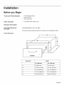
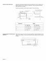
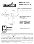
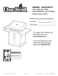
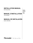
Warming Drawer
Models:
HWD27, HWD30
i!i_!!i_!_i_iii!i_!i!iii!_i_i_!ii!_!_!_!_!_!i_Ji_i_!!!!!_!_!!_!iii!i_i_
¸ .......
,,_,,,_,,
BOSCH
Table of Contents
Safety
......................................
Important Safety Instructions .......................................
Installation
..................................
1
1
3
Before you Begin .................................................
3
Tools and Parts Needed
3
Parts Included
..............................................................
General Information
Installation Procedure
Service
Data Plate
......................................................
3
..........................................................
........................................................
.....................................
.................................................................
5
7
7
This Bosch Appliance is made by
BSH Home Appliances Corporation
5551 McFadden Ave.
Huntington
3
Beach, CA 92649
Questions?
1-800-944-2904
www.boschappliances.com
We look forward to hearing from you!
Safety
Important Safety Instructions
READ AND SAVE THESE INSTRUCTIONS
WARNING:
If the information in this manual is not followed exactly, fire or shock may result
causing property damage or personal injury.
WARNING:
Do not repair or replace any part of the appliance unless specifically recommended
in the manuals. Improper installation, service or maintenance can cause injury or
property damage. Refer to this manual for guidance. All other servicing should be
done by a qualified technician.
Appliance Handling Safety
Hidden surfaces may have sharp edges. Use caution when reaching behind or
under appliance.
Safety Codes and Standards
This appliance complies with one or more of the following Standards:
•
UL 858, The Standard for the Safety of Household Electric Ranges
•
UL 923, The Standard for the Safety of Microwave Cooking Appliances
•
UL 507, The Standard for the Safety of Electric Fans
•
ANSI Z21.1, The American National Standard for Household Cooking Gas
Appliances
•
CAN/CSA-C22.2
No. 113-M1984 Fans and Ventilators
•
CAN/CSA-C22.2
No. 61-M89 Household Cooking Ranges
It is the responsibility of the owner and the installer to determine if additional
requirements and/or standards apply to specific installations.
Electric Safety
Before you plug in the electrical cord, be sure all controls are in the OFF position.
For appliances equipped with a cord and plug, do not cut or remove the ground
prong. It must be plugged into a matching grounding type receptacle to avoid
electrical shock. If there is any doubt as to whether the wall receptacle is properly
grounded, the customer should have it checked by a qualified electrician.
If required by the National Electrical Code (or Canadian Electrical Code), this
appliance must be installed on a separate branch circuit.
Installer - show the owner the location of the circuit breaker or fuse. Mark it for easy
reference.
Important - Save these instructions for the local electrical inspector's use.
Before installing, turn power OFF at the service panel. Lock service panel to prevent
power from being turned ON accidentally.
Refer to data plate for more information. See "Data Plate" under "Service" for data
plate location.
English 1
Important Safety Instructions
READ AND SAVE THESE INSTRUCTIONS
Be sure your appliance is properly installed and grounded by a qualified technician.
Installation, electrical connections and grounding must comply with all applicable
codes.
Related Equipment Safety
Remove all tape and packaging before using the appliance. Destroy the packaging
after unpacking the appliance. Never allow children to play with packaging material.
Never modify or alter the construction of the appliance. For example, do not remove
leveling legs, panels, wire covers or anti-tip brackets/screws.
CAUTION:
For units with glass panels, use care when handling glass to avoid breaking. Broken
glass could cause injury.
English 2
Installation
Before you Begin
Tools and Parts Needed
•
T-20 6-lobe screwdriver
•
Measuring tape
•
Drill with bit (1/8")
Parts Included
T-20 6-lobe screws, #8xl/2" (8)
General Information
Power Requirements and
Grounding
Circuit Specifications: 120V, 15A, 60Hz
The outlet must be properly grounded in accordance with all applicable codes.
Overall Dimensions
,
B
o
@ BOSCH
Dimension
Model
27" (685 mm)
30" (762 mm)
A
25" (634 mm)
28" (710 mm)
B
10 3/4" (274 mm)
10 3/4" (274 mm)
C
22 1/4" (565 mm)
22 1/4" (565 mm)
D
11 7/16" (289 mm)
11 7/16" (289 mm)
E
26 5/8" (676 mm)
29 5/8" (752 mm)
English 3
Cabinet Cutout Dimensions
Instructions are based on standard American cabinets 36" (914 mm) high and 24"
(609 mm) deep with a 25" (635 mm) countertop. If using non-standard cabinets,
alter dimensions accordingly.
Cabinet opening bottom must be able to support 110 pounds (50 kg).
Allow 3-1/2" (88.9mm) in front
1/2" (12 7mm)
[--Frame Overlaps
_L
1-1/2" (38 lmm) min. to
Fopening
above
Cab_in_et ....
t
t
B
pl -c
for drawer handle clearance
I
I
J
Walt
1/2"
Receptacle
(12 7ram)
_D
A
D
Frame
Overlaps
Cabinet
Dimension
Custom Drawer Front Dimensions
(Optional)
Model
27" (685 mm)
30" (762 mm)
A
25 3/8" (645 mm)
28 3/8" (721 mm)
B
11 1/8" (283 mm)
11 1/8" (283 mm)
C
24" (610 mm)
24" (610 mm)
Build custom drawer front to the dimensions specified in the following table. All four
edges must be finished. If using wood, the back must be sealed to prevent moisture
damage.
A
!
G
E
F
--_-_
Pi!ot Holes J_'_
I/2" (12.7 mm)
Diameter Hole
l
C
oI_L
English 4
Dimension
Installation
Model
27" (685 mm)
30" (762 mm)
A
26 3/4" (679 mm)
29 3/4" (755 mm)
B
11 1/4" (286 mm)
11 1/4" (286 mm)
C
3 5/8" (93 mm)
3 5/8" (93 mm)
D
2 3/16" (55 mm)
2 3/16" (55 mm)
E
2 5/8" (66 mm)
2 3/4" (69 mm)
F
1 5/8" (40 mm)
1 5/8" (40 mm)
G
21 1/2" (547 mm)
24 3/8" (618 mm)
Procedure
Before
installing, turn power OFF at the service panel. Lock service
AUTION:
panel to prevent power from being turned ON accidentally.
_
1.
Prepare cabinet cutout.
Prepare cabinet cutout and install electrical connection according to the
dimensions in "General Information".
2.
Remove drawer.
1) Pull drawer to fully open position.
.
2)
Press down right drawer clip.
3)
Lift up left drawer clip.
4)
Firmly pull the drawer straight out. Retract cabinet rails while drawer is
removed.
Connect power cord.
Insert plug into three-prong, grounded outlet. See "Power Requirements and
Grounding" above for electrical specifications.
English 5
4. Installwarmingdrawer.
It is
recommended to have 2 installers to install warming drawer. Failure
AUTION:
to do so may result in property damage or personal injury.
_
Slide warming drawer assembly into cutout until it is flush with cabinet. Secure
through four screw holes in front frame (drill pilot holes in cabinet first if
necessary).
5.
Attach custom drawer front (optional).
Use
care when handling glass panel to avoid breaking. Broken glass
AUTION:
could cause injury.
_
6.
1)
Prepare custom drawer front as explained above.
2)
Remove drawer from warming drawer frame (See Use and Care Manual for
instructions).
3)
Remove six screws from backside of drawer front. Set handle and screws
aside.
4)
Remove signal light lens from glass panel and set aside. Discard glass
panel (Note: stainless steel models do not have a glass panel).
5)
Install the signal light lens in the custom drawer front.
6)
Attach drawer front with six screws. Attach handle as well if desired.
Replace drawer.
1)
Be sure cabinet rails are pushed inside cabinet.
2)
Align the drawer rails with the cabinet rails.
3)
Firmly push the drawer straight into the cabinet until drawer clicks into
place.
4)
Open and close drawer to test operation. Note: if the drawer will not close,
verify that the rail clips are properly positioned.
7.
Turn power on at the service panel.
8.
Test the installation.
Turn the warming drawer on. Signal light and timer should turn on immediately.
Check for warmth.
English 6
If the warming drawer elements or signal light do not turn on, check the power
source to see if the circuit breaker is tripped.
See Use and Care Manual for troubleshooting
the Use and Care Manual.
information. Refer to the Warranty in
To reach a service representative, see the contact information at the front of the
manual. Please be prepared with the information printed on your product data plate
when calling.
Data Plate
The data plate shows the model and serial number. Refer to the data plate on the
appliance when requesting service. The data plate is visible on the left side of the
drawer casing. It may be necessary to remove the drawer to view it.
Data Plate
o
@ BOSCH
English 7
Notes:
Nnvented for life
5551 McFadden Avenue, Huntington Beach, CA 92649 • 800-944-2904 ° www.boschappliances.com
9000209585 ° 5V0AND ° Rev. B ° 04/07 © BSH Home Appliances Corporation, 2007 ° All rights reserved
Litho in USA