1
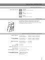
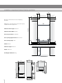
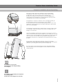
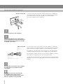
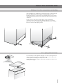
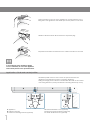
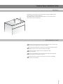
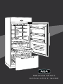
PREMIUM SERIES
I N S TA L L AT I O N G U I D E
Premium Series Installation Guide
Index
Page
Important safety instructions
3
Children Safety
3
Appliance features and installation requirements
3
Installation compartment features
4
899 Premium Maxi Series
749 Premium Standard Series
599 Premium Wine Cellar Series
Transport to installation site and unpacking 7
Electrical and Water connection 8
Building-in into the compartment and levelling
9
Anti-tipping safety assembly
9
Application of side and central profiles
10
Ventilation
11
Post installation control
12
Start up
12
1
2
Premium Series Installation Guide
Important safety instructions
Symbols used in the Guide
Important
Directions for avoiding appliance
damage
Note
Tips for the correct use of the
appliance
Warning
directions for preventing injury
Children safety
If this appliance is replacing an existing appliance which must be
removed or disposed of, make sure that it does not become a
dangerous trap for children by cutting its power supply cable and
rendering it impossible to close the door. Use the same caution at the
end of the lifespan of the new appliance.
Appliance features and installation requirements
Appliance dimension
Wine Cellar Series Premium Standard Series
Premium Maxi Series
w: 585 mm / h: 2150 mm / d: 700,5 mm
w: 735 mm / h: 2150 mm / d: 700,5 mm
w: 885 mm / h: 2150 mm / d: 700,5 mm
Appliance dimension
with packaging
Wine Cellar Series Premium Standard Series
Premium Maxi Series
w: 650 mm / h: 2300 mm / d: 800 mm
w: 800 mm / h: 2300 mm / d: 800 mm
w: 950 mm / h: 2300 mm / d: 800 mm
Weight with packaging
Wine Cellar Series up to 236 kg
Premium Standard Series up to 268 kg
Premium Maxi Series up to 315 kg
Voltage
AC 220-240V
Power supply cable
13 Amp plug
Potable water supply presure
Water supply tube
from 0.05 MPa to 0.5 MPa (0.5 Bar - 5 Bar)
3/4” female attachment
Provided installation accessories
Anti-tipping Kit (kit B04000200)
4 mm allen wrench.
Additional equipment necessary
for installation not provided
Phillips head screwdriver
Wood and percussion drill
8 mm bit for masonry
17 mm wrench
3
Installation compartment features: Premium Maxi Series
A
A
A: area to be left clear for the anti-tipping
brackets
100
140
100
140
E - W: area to be left clear for the power supply
cable and water supply hose.
> 2165
Minimum Niche Height: 2165 mm
900
Minimum Niche Width: 900 mm
Door Swing Clearance: 1602 mm
Door Opening Right Clearance: 216,5 mm
102,5
102,5
695
98
33
Door Opening Angle: 105°
E
W
Width: 885 mm
Minimum Height: 2160 mm
660
Depth: 700,5 mm
Net Weight: AFR9FTCR 257 kg
700,5
885
660
8
195
885
2150
1602
1295,3
1243,5
216,5
625
740,5
4
130
643,7
513,7
8
10
5°
Premium Series Installation Guide
Installation compartment features: Premium Standard Series
A
A
A: area to be left clear for the anti-tipping
brackets
100
140
100
140
E - W: area to be left clear for the power supply
cable and water supply hose.
> 2165
Minimum Niche Height: 2165 mm
750
Minimum Niche Width: 750 mm
Door Swing Clearance: 1335.5 mm
Door Opening Right Clearance: 176 mm
102,5
102,5
545
98
33
Door Opening Angle: 105°
E
W
Width: 735 mm
Minimum Height: 2160 mm
660
Depth: 700,5 mm
Net Weight: AFFR7FTCR 210 kg
700,5
735
660
195
735
2150
1295,3
1333,5
1243,5
8
176
5°
625
740,5
130
643,7
513,7
8
10
5
Installation compartment features: Wine Cellar Series
A
A
A: area to be left clear for the anti-tipping
brackets
100
140
100
140
E - W: area to be left clear for the power supply
cable and water supply hose.
> 2165
Minimum Niche Height: 2165 mm
600
Minimum Niche Width: 600 mm
Door Swing Clearance: 1305,5 mm
Door Opening Right Clearance: 137 mm
102,5
102,5
394
98
33
Door Opening Angle: 105°
E
W
Width: 585 mm
Minimum Height: 2160 mm
660
Depth: 700,5 mm
Net Weight: AFWL6 195 kg
700,5
585
660
195
585
2150
1295,3
1305,5
1243,5
8
137
625
740,5
6
130
643,7
513,7
8
10
5°
Premium Series Installation Guide
Transport to installation site and unpacking
Since this is a large and heavy appliance, before transporting
the appliance, check the access to the location where it will be
installed (door size, manoeuvring space in stairwells, etc.).
It may be convenient to remove a part of the packaging before
transporting to the installation site, taking maximum care to protect
the appliance from scratches and damages.
The appliance is secured to the base of the packaging (pallet) by
four bolts which can be removed using a 17 mm wrench.
It is recommended to use a manual transporting device to move the
appliance to the installation site, and only at this point to remove the
base of the packaging.
The appliance should always be transported in an erect position. If this
is not possible, transport it laying on its rear side, avoiding at all costs
laying it on its front side.
Once the installation site has been reached, it is necessary to remove
the four anchor bolts that hold the appliance to the pallet (use a 17 mm
wrench). Once at the installation site, the appliance, which is equipped
with four wheels, can be taken off the pallet (two slide guides are
provided for this purpose, see illustration) and positioned in the correct
location.
Be extremely careful during this operation, and do not lean the
appliance any more than necessary when placing it on the slide guides
(max 70°< ) to avoid grave harm to persons and property.
Be very careful to avoid any damage to floors. Especially delicate
floors should be protected with plywood, hard cardboard or similar
material panels.
The appliance is very heavy.
Take maximum care during handling
to avoid injury.
The appliance should always be transported
in an erect position.
Avoid at all costs leaning it on its front side.
7
Electrical and Water connection
Electrical connection
A 13 Amp socket with an efficient earth should be made available for
the electrical mains connection, as well as an omnipolar switch which
can easily be reached after the appliance has been installed.
Do not use extension cords or adapters.
Do not use extension cords or adapters.
Make sure that the the power supply cable is
properly plugged into its seat as per drawing on
facing page. The cable must be secured with
the specific cable clamp.
Water connection
For connection to the water supply system (for appliances equipped
with ice maker) a tap with a male 3/4” connection should be provided,
which must also be easily accessible once the appliance is installed.
The appliance is provided with a water supply hose and seal kit which
is suitable for high water pressure and complies the Food Regulations.
The water filter cartridge, which is provided with the appliance, should
be installed according to the accompanying instructions.
Use only the new hose and the new gaskets which are supplied with the
appliance. Discard any hose and gasket which may have already been
installed.
The built in filter cannot make safe for drinking
any water which is not suitable for human
consumption.
The appliance should be connected only
to a drinkable water supply system, in
accordance with current laws in the country
where the appliance is being installed.
8
Premium Series Installation Guide
Building - in into the compartment and levelling
After wheeling in the appliance into the final location, make it perfectly
level and aligned with other cabinets by adjusting the two front
leveling feet using a 17 mm wrench and adjusting the two rear wheels
using an 8 mm bush wrench on the devices located at the base of the
appliance.
To get access to the power supply cable, to the water fill hose
connection and to the rear wheels adjusting devices you must first
remove the two front ventilation grilles, which are fixed to the cabinet
by means of some self tapping screws.
8 mm
55
Anti - tipping safety assembly
75
85
To avoid danger of the appliance tipping over when opening full doors
and drawers, it is mandatory to install two brackets on the upper part
of the appliance for fixing it securely to the wall.
The brackets should be applied as illustrated using the provided screws
and expansion plugs.
9
Place a bracket on the top of the appliance in correspondence to the
fixing holes and against the wall. Mark up the holes position on the wall.
Drill the wall with an 8 mm bit and insert the expansion plug.
Reposition the bracket and fix it first to the cabinet and then to the wall.
To avoid danger of the appliance tipping
over it is mandatory to secure the appliance
to the wall by means of two special brackets.
Application of side and central profiles
Aluminium profiles can be used to close the spaces between the
appliance and adjacent structures or another appliance.
During the design process take into consideration the width of the central
connecting elements (13 mm) and lateral connecting element (6.5 mm).
A
A
A
6,5
6,5
C
D
A Appliance
B Adjacent structure
C Central connecting element (optional)
10
B
A
A
6,5
E
F
D Central aluminium cover (optional)
E Lateral connecting element (optional)
F Lateral aluminium cover (optional)
B
Premium Series Installation Guide
Ventilation
Ventilation is insured by a forced air system through a grille located
in the upper part of the appliance.
This grille should never be covered by panels or any other devices
that could reduce its efficiency.
Post installation control
Check that the connection to the water system does not have any
leaks and that the closing tap is easily accessible
Check that the electrical connection is correctly installed and that
the multipole switch and socket are easily accessible
Check the perfect alignment of the appliance with
adjacent structuress
Check that all adhesive tape and external or internal temporary
protective devices have been removed
Check the perfect closure of the doors and the smooth sliding
of the drawers and shelves.
11
Start up
To start the appliance, connect the plug to the electrical mains:
at this point, when opening the door, the control panel will usually
visualize the message “Stand by”, and all the panel keys be off
ON/OFF
3
Before starting
3.1
Know your appliance
Congratulations for having purchased your new Aga
Refrigeration unit: from now on you can use our innovative
storage system, which will allow you to keep all of your food
in the best way possible.
This manual will answer most of your questions about the
product’s features. Should you require further information,
please call our Customer Service Team on 0845 602 3015
Before calling, write down the model type and serial
number which are available on the warranty certificate and
on the rating plate located on the inside the refrigerator
compartment (behind the water filter flap door on models
provided with Ice Maker) and any messages which may
have appeared on the display.
FRIDGE
To turn on all the appliance compartments, press the On/Off
button
for three seconds.
The display will show the message “Initial test” for approx. 2 minutes.
After this phase the compressors will start up and remain on until the
default temperature set up in the factory is reached. Do bear in mind
that this condition could last several hours.
If the appliance is provided with an Ice Maker, prior to switch it on make
sure that the water filter cartridge is installed, then fill the water system.
To this purpose switch off the Ice Maker.
Touch the Enter
and Ice Maker
buttons at the same time, to start
the filling which may last a few minutes.
At the end switch the Ice Maker on again by touching the
button.
MENU
Before starting
3
Main components
3.3
1
For further information about the appliance operation, refer to the
User Manual.
8
9
2
10
3
11
12
4
5
6
13
3.2
Main features
7
The Aga TriMode refrigeration system and the efficient
separation of internal compartments ensure maximum
freshness and offer excellent storage of foods in the three
compartments: refrigerator, Fresco and freezer
Ample drawers with Soft self-closing systems
in the Fresco area
It is also possible, should there be a need, to further
increase the flexibility of the appliance by making
the freezer compartment operate as a refrigerator
or as a Fresco compartment
Easily replaceable water filter located inside
the refrigerator
The Fresco compartment has a low temperature
and controlled humidity, providing excellent storage
in maximum safety conditions for fresh foods
Electronic control guarantees constant temperature
and humidity levels set by the user
An interactive menu allows customised management
of appliance functions and the visualisation of
functioning messages
Power save features to reduce consumption during
holiday periods
14
15
Ice Maker for automatic ice production in the desired size
Patented sliding shelf system, with shelves that
can be positioned at any level inside of the refrigerator
without having to be removed
Premium Series
Stainless steel surface inside and coloured finish outside
1 Aga colour finish
10 Sound signals
Patented hinge system that permits automatic door closing
2 Control panel with Menu
11 Holiday function
External drawers with to self-closing system
3 Patented shelf positioning system
12 Spacious door shelves
Localised lighting with LEDs and neon lights
4 Water filter
13 Innovative lighting
Anti-tipping system by means of wall mounting brackets
5 Control panel, Fresco area
14 Automatic door and drawer closure
6 Fresco compartment with controlled humidity
15 Freezer compartment that can
be transformed into a refrigerator
or Fresco compartment
(TriMode function)
7 Automatic icemaker
8 Double refrigeration system
9 Temperature display
4
5
If at the first start up the message Stand-by does
not appear, but other messages appear, such
as Fridge too warm, Fresco too warm, Freezer
too warm, or sound signals are activated, it
means that the appliance has already started
the cooling process.
If this is the case, deactivate any possible
acoustic signals by pressing the Alarm
button, close the door and wait until the set
temperature is reached.
12
04-09-2008
A090004-00 EN
Contact 0845 815 2020
Station Road, Ketley, Telford, Shropshire, TF1 5AQ England.
www.aga-web.co.uk
Aga is a trading name of Aga Consumer Products Limited, part of the Aga Rangemaster Group plc.
Registered in England & Wales under Registered Number 3872754.
Registered Office Address - 4 Arleston Way, Shirley, Solihull B90 4LH