1
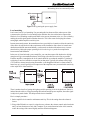
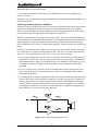
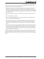
®
Technical Paper
Number 103
. . . Level Matching for Autosound . . .
?or Why is my system so noisy?
by
Richard Chinn
All Rights Reserved. Copyright 1986.
Rick Chinn is a working sound engineer who has been involved in all facets of
recording, sound reinforcement and acoustical design for the past fifteen years.
He has written articles for Modern Recording and Music, Music and Sound
Output and A/V Video and has worked for TAPCO and Kaye-Smith studios.
®
22410 70th Avenue West, Mountlake Terrace, WA 98043 (425) 775-8461
Price $1.00
Contents
Page
Introduction . . . . . . . . . . . . . . . . . . . . . . . . . . . . . . . . . . . . . . . . . . . . . . . . . . . . . . . . . . . . . . . . . . 1
What is noise? . . . . . . . . . . . . . . . . . . . . . . . . . . . . . . . . . . . . . . . . . . . . . . . . . . . . . . . . . . . . . . . . 2
Thermal Noise . . . . . . . . . . . . . . . . . . . . . . . . . . . . . . . . . . . . . . . . . . . . . . . . . . . . . . . . . . . . . . . . 2
Induced Noise . . . . . . . . . . . . . . . . . . . . . . . . . . . . . . . . . . . . . . . . . . . . . . . . . . . . . . . . . . . . . . . . 2
Ground Loops . . . . . . . . . . . . . . . . . . . . . . . . . . . . . . . . . . . . . . . . . . . . . . . . . . . . . . . . . . . . . . . . 3
The Meaning of Signal-to-Noise Ratio . . . . . . . . . . . . . . . . . . . . . . . . . . . . . . . . . . . . . . . . . . . . . 4
The noise floor, or the Ultimate noise . . . . . . . . . . . . . . . . . . . . . . . . . . . . . . . . . . . . . . . . . . . . . . 4
Peak clipping, or the peak ceiling . . . . . . . . . . . . . . . . . . . . . . . . . . . . . . . . . . . . . . . . . . . . . . . . . 4
Operating level, headroom and signal-to-noise ratio . . . . . . . . . . . . . . . . . . . . . . . . . . . . . . . . . . 4
Gain, Level, Sensitivity, and Power Relationships . . . . . . . . . . . . . . . . . . . . . . . . . . . . . . . . . . . . 6
The old volume control myth............... . . . . . . . . . . . . . . . . . . . . . . . . . . . . . . . . . . . . . . . . . . . . 6
The impedance problem..................... . . . . . . . . . . . . . . . . . . . . . . . . . . . . . . . . . . . . . . . . . . . . . 7
Minimizing Noise in Autosound Systems . . . . . . . . . . . . . . . . . . . . . . . . . . . . . . . . . . . . . . . . . . . 8
Identifying noise sources . . . . . . . . . . . . . . . . . . . . . . . . . . . . . . . . . . . . . . . . . . . . . . . . . . . . . . . . 8
Grounding practices . . . . . . . . . . . . . . . . . . . . . . . . . . . . . . . . . . . . . . . . . . . . . . . . . . . . . . . . . . . 9
Wiring practices . . . . . . . . . . . . . . . . . . . . . . . . . . . . . . . . . . . . . . . . . . . . . . . . . . . . . . . . . . . . . 10
Level matching . . . . . . . . . . . . . . . . . . . . . . . . . . . . . . . . . . . . . . . . . . . . . . . . . . . . . . . . . . . . . . 11
Interfacing with internal power amplifiers . . . . . . . . . . . . . . . . . . . . . . . . . . . . . . . . . . . . . . . . . 12
Conclusion . . . . . . . . . . . . . . . . . . . . . . . . . . . . . . . . . . . . . . . . . . . . . . . . . . . . . . . . . . . . . . . . . 14
Procedure for Head Units . . . . . . . . . . . . . . . . . . . . . . . . . . . . . . . . . . . . . . . . . . . . . . Appendix A
Final Setup for the EQX . . . . . . . . . . . . . . . . . . . . . . . . . . . . . . . . . . . . . . . . . . . . . . . Appendix B
Procedure for Powered Radios . . . . . . . . . . . . . . . . . . . . . . . . . . . . . . . . . . . . . . . . . . Appendix C
®
. . . Level Matching for Autosound . . .
?or Why is my system so noisy?
Introduction
With the advent of really high-performance automotive sound systems, the old problem of noise (in
its various forms) has once more raised its ugly head. Even if the manufacturer has done their
engineering homework, it’s still really easy to forget some detail during installation and make even
the quietest components seem noisy.
Consider:
• A head unit with an integral power amplifier.
• An outboard equalizer, with input and output level controls.
• An outboard power amplifier, with high- and low-level inputs.
What we have here is a potential disaster. If the level adjustments between the various components
aren’t made correctly, the finished system could be any of the following:
• Noisy
• Distorted
• Seemingly under powered
In this guide, we’ll discuss some of the causes of noise in audio systems and explore some ways of
dealing with them. Along the way, we’ll also cover the interface problem listed above. At times,
this guide may seem a bit long-winded. It is, but the risk of spreading misinformation by oversimplification is quite high so do yourself a favor and stick with us; the time you spend reading this
will be well spent.
1
®
What is noise?
In any audio system, there are several potential noise sources.
• thermal noise
• induced noise
• noise caused by a ground loop
Thermal Noise
Thermal noise sounds like the hiss that you hear between stations on your FM radio. Thermal noise
occurs because mankind chooses to live at 300 degrees above absolute zero. Thermal noise occurs
because of the random movement of electrons caused by thermal agitation. At absolute zero,
thermal agitation ceases to exist. Unfortunately, we haven’t found a way around this problem yet.
Just because we live at temperatures other than absolute zero doesn’t mean that we can’t deal with
thermal noise. Careful design, along with attention to detail can minimize this type of noise.
Remember...the word is minimize not eliminate.
Induced Noise
Induced noise has a variety of causes. Induced noise is sneaky. Sometimes it gets into your system
through the power wiring, other times, it may sneak in via two adjacent wires. Still other times, it
just gets in through the air.
Although a car is powered by a battery, (and everyone knows that batteries put out pure DC) the
automobile electrical system is one of the nastiest environments known to electronic equipment.
The alternator, which generates power to recharge the battery while the engine is running, puts
high-current pulsating DC into the battery, which shows up everywhere else in the electrical
system. Alternator noise sounds like a whine whose pitch is proportional to engine speed.
The alternator wiring carries fairly high currents, even though the voltage is relatively low. Passing
an electrical current through a wire is a sure-fire way to generate a magnetic field. Higher currents
generate higher strength fields. Now, if you put two wires in close proximity to each other, and one
of them is carrying an electric current, you can generate electricity in the other by one of two
methods:
1. Move one of the wires relative to the other.
2. Vary the electric field.
Since the alternator puts out alternating current method two applies here. This is the very same
principle that a transformer (not the guys on Saturday morning TV) uses. Imagine what could
happen if the other wire was the lead from the head unit to the power amplifier.
The last cause of induced noise is electromagnetic interference (EMI). This is the same method that
radio transmitters use. Basically, the sound system’s wiring becomes an antenna, and the amplifiers
within the system become the receiver. Unfortunately you don’t want to listen to the interfering
station. Some examples of EMI are ignition noise or perhaps the loud buzz that you hear if you
drive near a television transmitter.
2
®
What is Noise?
Ground Loops
Ground loops are insidious. They are caused by the non-zero resistance of the wire used to interconnect the equipment. Typically, ground loops are created by a piece of equipment having multiple connections into the grounding system.
In autosound, this problem is exacerbated by the rather callous belief by auto makers and certain
other folks that the metal frame of the vehicle makes a good ground. While this may be true for
cigarette lighters and tail lights, applying this belief to audio systems is a gilt-edged invitation to
disaster.
Figure 1 shows what happens. Generally, the audio wiring has higher resistance than the power
wiring. Since the electrical system of the car uses the body/frame structure as it’s negative return,
the non-zero (yes, it’s small, but not small enough!) resistance of the car body allows small voltage
drops to be created between various points in the car body.
Figure 1. Anatomy of a ground loop.
The alternator in the battery charging system makes things worse because the frequency of it’s AC
output (alternating current...that’s why it’s called an alternator, not a generator) is easily within the
audible range. The low impedances involved (high available current means low impedances) make
filtering out alternator noise even more difficult. Anyway, these voltage drops occurring between
various points in the car body usually have alternator noise riding on them, which gets into a sound
system via a ground loop.
Until you’ve traced out a noise problem, and found it to be a cleverly concealed ground loop, the
phrase “ground isn’t Ground” just sounds like random noise from another audio fanatic. All it
takes is one good ground loop problem to turn the hardiest skeptic into a believer.
3
®
The Meaning of Signal-to-Noise Ratio
Signal-to-noise ratio is a common term used on spec sheets. As common as it is, many people (both
learned and not) misunderstand or misuse it. Signal-to-noise ratio is the relationship between a
device’s normal operating level, the noise floor, and peak clipping.
The noise floor, or the Ultimate noise
All electronic equipment operating above absolute zero generates noise. Fortunately, modern
electronic design techniques can identify each noise source, all the way from the tape head in a
cassette machine, to each stage in the amplifiers following it on the way to the speakers. Careful
design minimizes each potential source, resulting in optimum performance. Of course, cost is a
limiting factor in the overall design process at least if most of us are to be able to purchase the
device. The bottom line is the thermal noise generated by the electrical resistance of the source. In
the case of a cassette machine, the source is the tape head itself. Even if the amplifiers following it
were noiseless, they would still amplify the thermal noise of the head itself. This then is the Ultimate noise.
The normal, residual noise output of any electronic device is known as its noise floor. Again, it is
the product of the thermal noise of the source, plus the noise contributions of each succeeding
amplifier stage.
Peak clipping, or the peak ceiling
At the other end of the scale is peak clipping. Peak clipping occurs when an amplifier’s output
signal can no longer rise as directed by the input signal. Typically, it occurs when the peak value of
the output signal attempts to exceed the value of the power supply voltages supplied to the amplifier stage.
Figure 2 shows this graphically. The amplifier supply voltages are + and - 12 volts. The signal can
vary around ground (zero volts), up to 12 volts positive (above ground) or 12 volts negative (below
ground). If the signal were to try to exceed this limit, clipping occurs once the instantaneous signal
level reaches 12 volts. At this time, the output can go no further, and the signal peak is truncated or
flattened until the signal level falls below 12 volts. The signal level at which clipping occurs is
known as the peak ceiling.
Figure 2. Clipping.
Operating level, headroom, and signal-to-noise ratio
Somewhere between the noise floor and peak clipping is the normal operating level of a device.
Looking at this relationship graphically (Figure 3), the distance (difference) between operating
level and the noise floor is known as the working signal-to-noise ratio. Finally, the distance between peak clipping and the noise floor is known as the dynamic range.
4
®
Meaning to Signal-to-Noise Ratio
Figure 3. The relationship between operating level, clipping and the noise floor.
As you can see, the operating level chosen for any given device has a pretty direct effect on the
working signal-to-noise ratio. Pick a level that is too high and you get premature peak clipping (but
spectacular noise performance). Pick a level that is too low and you have lots of headroom, but a
poor working signal-to-noise ratio. Let’s put some numbers on this: a hypothetical unit, with a 70dB noise floor, and a +10 dB clipping level.
Right off, you can see that there is a maximum dynamic range of 80 dB (+10 - -70). Now, let’s
explore a few different operating levels. First, we’ll used -20 dB which corresponds to a signal
level of around 0.1 volt. At -20 dB, the working signal-to-noise ratio is 50 dB (-70 - -20), which is
okay, but not spectacular. At this same level, we have 30 dB of headroom (+10 - -20).
Now let’s push the operating level up to -10 dB, about 0.3 volt. See if you can do the math yourself. The working signal-to-noise ratio is 60 dB and we have 20 dB of headroom. As you can see,
there is always a tradeoff between signal-to-noise and headroom. For our make-believe unit, this
would be a good level to operate it at.
Some manufacturers have been known to specify the dynamic range as the signal-to-noise ratio.
For the unwary person who only looks at numbers without really understanding them, this gives a
truly spectacular number. Only under the most optimistic of operating conditions could the dynamic range of a device be construed as the signal-to-noise ratio. The condition under which this is
true is where the headroom remaining is precisely zero dB.
The optimum operating level is a compromise between headroom and working signal-to-noise (s/n)
ratio. For most systems, 60 to 80 dB of working s/n is adequate and practical. Likewise, there
should be at least 16 dB of headroom to accommodate signal peaks. Picking the right operating
level for each component in the system allows you to set the working signal-to-noise ratio/headroom tradeoff.
5
®
Gain, Level, Sensitivity, and Power Relationships
Another source of error is the interrelationship between gain, signal level, sensitivity, and output
power. First some definitions:
Gain
Generally this is shorthand for voltage gain. A measure of the amplification factor
of an amplifier, or the output voltage divided by the input voltage. Thus, 10 volts
out for 1 volt in is a gain of 10. Sometimes gain figures are converted into decibels
(dB). In this case, a voltage gain of 10 converts to a voltage gain of 20 dB. It’s
handy to use decibels for gain calculations because the only math you need is
simple addition and subtraction (once you do the decibel conversion).
Signal Level
This is the strength of a signal, measured in volts. Again, sometimes signal levels
are measured in decibels, which states them as a ratio of two quantities: the signal,
and a known reference level. Signal levels are also referred to by their ability to
drive an input: line level, speaker level. While the voltage present may be the
same, the current (amperage) capability may not be the same. Basically, this is
what is different between a 1 volt line level signal and a 1 volt speaker level
signal.
Sensitivity
This is a measure of the input signal requirement of a device for some stated
output level. Sensitivity is intimately related to gain. If an amplifier has a gain of
10, and it’s rated output level is 10 volts, then it’s sensitivity is stated as 1 volt.
It’s important to remember that low sensitivity means a higher voltage is necessary
to drive the unit, while high sensitivity means less voltage is required. Note that
sensitivity has nothing to do with power output.
Power Output Power represents energy, which can do work (like moving a loudspeaker cone).
Power is always measured in watts. Power has nothing directly in common with
sensitivity. It is equally possible to have an amplifier that has low sensitivity, but
high power output as well as one that has high sensitivity, but low power output.
The old volume control myth
A common old wives tale is the belief that the percentage rotation of the volume control represents
the same percentage of output power. Here’s the way it goes: “I’ve got so much power that I only
need to turn up the volume to 10 o’clock (20% rotation)”. Since the volume control generally
adjusts the overall gain of the system, there is one unique signal level where wide open (100%
rotation) represents full power output from the power amplifier. Since most volume controls are
followed by gain (to make interfacing varied signal sources easier), the average system reaches full
power long before 100% rotation is reached. Thus, the amount of volume control rotation required
to drive the system to full output depends on:
1. The signal level present at the input of the volume control.
2. The amount of gain following the volume control.
3. The sensitivity of the power amplifier (better low than high, from a noise standpoint).
Why bother? A good reason is to make sure that the signal going to the power amplifier is as
strong as possible. This helps to subjectively reduce noise that may be induced between the head
unit and the power amplifier by making the signal in the cable much stronger than the induced
noise.
6
®
Gain, Level, Sensitivity, and Power Relationships
Another reason is to maximize the amount of useable range that the volume control has, which is
especially useful with units that have detented (click-stepped) volume controls. The volume control
taper (rate-of-change vs. amount of rotation) at the low end of the control is necessarily coarse.
After all, most people like to be able to shut the sound off once in a while. A system that is too
loud when the control is three clicks from off isn’t very useful unless the owner is a hardened
volume freak. Remember to explain to the owner than even though the control must be turned “way
up”, that they are still getting full performance out of the amplifier.
The impedance problem
Another old bugaboo is the “matching” of impedances. Let’s put this one to rest right now.
In a contemporary audio system, there is no need to match impedances, except where
maximum POWER transfer is desired. Currently, the only place where this is true is at the
antenna terminals of a radio receiver.
If we don’t match impedances, then what do we do? Simple...make sure that the output impedance
of the source is less than the input impedance of it’s load. Thus, a head unit with a 1000 (lK0 ohm
output impedance is fine driving an amplifier with an input impedance of 10,000 (10K) ohms. On
the other hand, a head unit with an output impedance of 10,000 ohms is not okay looking at a
power amplifier with an input impedance of 1000 ohms.
Let’s take a moment and look at amplifier and speaker “matching.” As mentioned previously, the
only place where impedance matching is desirable is where you are interested in maximum power
transfer. Impedance matching occurs where the actual source impedance equals the actual load
impedance (i.e. 8 ohm source, 8 ohm load). For a typical solid-state amplifier, the actual output
impedance is perhaps 0.01 ohm. Why do the manufacturers tell us that the amplifier is intended for
a 2 ohm load? What they are really telling us is:
This amplifier is suitable for load impedances down to a minimum of 2 ohms.
What would happen if we were to actually try to match impedances, in the strict sense of the word.
If the amplifier were perfect (technologically impossible), we’d have a very large power output
figure.
For example, let’s create a fictitious amplifier that not only has a 0.01 ohm output impedance but
can actually drive a 0.01 ohm load (speaker). This amplifier has a 4 ohm power rating of 50 watts.
Doing a bit of quick math, this means that the amplifier will develop 14.14 volts across a 4 ohm
load. Now if we drop the load (speaker) impedance to 0.01 ohms (remember, we said matched
impedances) then this amplifier will deliver 20,000 watts of output power, albeit into a 0.01 ohm
load. If you’re not afraid of the math, the power in the load is the voltage squared, divided by the
load impedance. For our hypothetical amplifier:
Power = (14.14 x 14.14) / 4, or 50 watts.
If you tried this in the real world and the amplifier was well designed, it would do the best it could
(basically it would stop at around 50 watts output) and probably get quite hot under the collar. If
the amplifier weren’t so well designed, then it might destroy itself trying to drive the abnormal
load. That’s why you can’t just keep connecting speakers to an amplifier unless you’re trying to
help the amplifier repairman buy a BMW.
7
®
Minimizing Noise in Autosound Systems
Now that we’ve established some of the causes of noise in any audio system, let’s apply them to a
typical autosound system. First let’s make some assumptions:
1. The manufacturer did their design homework and the unit represents the best that they could
1. do, considering their design constraints.
2. The unit meets its published specs.
Identifying noise sources
All the noise filtering in the world won’t help unless you can identify the various potential noise
sources in the system.
Alternator
Sounds like a whine whose pitch varies with engine speed. It can be
caused by poor or careless grounding, ground loops, poor wiring practices, or bad level matching. Bypassing the alternator output with a
capacitor may help.
Ignition
A ticking sound that changes with engine speed (the clicks get closer
together). It can be caused by poor or careless grounding, ground loops,
poor wiring practices, or bad level matching. Resistor spark slugs may
help, especially when tuners are affected.
Turn Signals
A clicking sound synchronized with the turn signals. Make sure that the
auto body ground connections to the lamps are secure. Bypassing the
input and/or output to the flasher unit with a capacitor may help. Other
possibilities include poor or careless grounding, ground loops, or bad level
matching.
Dash Lamp Dimmer
A buzzy whine whose pitch varies with the dimmer setting. Try bypassing
the dimmer input lead with a capacitor and/or different grounding points
for the autosound system.
Horn
A buzzing sound, synchronized with the horn (how did you guess?).
Again, a bypass capacitor should fix this too.
Amplifier Power Supply
High-powered amplifiers sometimes cause problems because the DC to
DC converter inside of them radiates EMI (electromagnetic interference)
into the electrical system of the car. This type of noise sounds like a nasty
buzz, that isn’t affected by engine speed and is usually affected by some
or all of the system controls. Sometimes (especially when the units are
mounted on a board in the trunk) the manufacturer will leave the chassis
of the amp floating (not connected). This turns the amp chassis into an
effective antenna. Connecting it to the auto body ground will turn the amp
chassis back into a shield, which is what it should be.
Figure 4 shows how to bypass the alternator output. It’s important to put the bypass capacitor as
close as possible to the source of the interference. Make sure that the ground connection (the
vehicle body is the place to use) to the capacitor is solid and clean. If you have an ohmmeter,
measure the resistance between the capacitor and the vehicle body. It should be less than 0.3 ohm.
8
®
Minimizing Noise in Autosound Systems
Figure 4. Bypassing the alternator output.
Grounding practices
CAUTION
Ground Isn’t Ground!
Remember those words. Any time that you think that grounding is a trivial matter recite those three
words.
The basic reason that we ground anything at all is to supply a negative return for the electric
current that operates a device. If you’re an auto maker, basically anything that is metal and somehow associated with the vehicle body is fair game. If you’re a state-of-the-art autosound installer,
that belief is the first and last mile on the road to ruin.
A second reason that things are grounded is so that their metal enclosures can act as a shield for
incoming EMI. Remember...the metal enclosures only act as a shield when they are grounded. This
helps keep portions of the circuitry that weren’t designed to be radio receivers from becoming radio
receivers.
Ground loops cause problems by allowing multiple paths into the grounding system. This wouldn’t
be such a problem if it were not for the finite and measurable resistance of the ground system.
When you combine the multiple current paths into the ground system caused by the auto maker’s
indiscriminate definition of the word ground and the finite resistance of the ground system you get
voltage drops. These voltage drops cause trouble when they get into an audio system via a ground
loop. What happens is that the audio system tends to amplify any noise present in the ground
system. The net result is noise.
Here’s some (heh-heh) ground rules:
1. There should be one and only one path to the negative side of the vehicle electrical system. If
you elect to use the vehicle body as this point, scrape the paint from under the contact point, and
use a lockwasher on both sides of the terminal lug.
In extreme cases, you may need to run a heavy gauge wire to the battery’s negative terminal.
Alternatively, you could use the point where the battery negative hits the vehicle frame. Again,
clean everything and use lockwashers. If the connection point is subject to vibration (like on the
engine), then be sure to use stranded or braided wire (braided is better) and leave enough slack
so that the entire length of wire can vibrate. This will help keep it from breaking.
9
®
Minimizing Noise in Autosound Systems
2. If you mount everything on a board, connect the chassis of each component to a good, solid
electrical ground. The vehicle body is a good choice here because what you want is a good RF
(radio frequency) ground. The wire running to the negative side of the electrical system has
inductance which raises it’s impedance at high frequencies. In effect, at radio frequencies, the
impedance could be high enough that the wire would look like an open circuit. Braided wire
works best here because it has low inductance.
3. It’s good insurance to use an ohmmeter to make sure that the chassis of each component isn’t
already tied to its internal electrical ground. Sometimes the case is tied to circuit ground through
a low to moderate value resistor. If the case to negative wire resistance is greater than 10 ohms,
then it’s you can connect the unit’s case to the auto body ground without causing a ground loop.
Some manufacturers put a switch on the unit to allow you to pick where the chassis is grounded.
If you supply the connection to the chassis of the unit make sure that the switch doesn’t supply
one too.
4. Some premium connecting cables have oversized connectors. Make sure that the shell of the
connector doesn’t inadvertently contact the chassis of the unit that it is plugged in to. If this
happens, you’ve got a ground loop on your hands.
5. When you think that you’ve got everything right, turn everything on, and disconnect the antenna
and the negative connection to the vehicle’s electrical system. If everything quits, you’ve got a
single point ground.
Remember: Ground isn’t ground!
Wiring Practices
After grounding, the rest is relatively easy. Here’s a few hints:
• Avoid running audio wiring along (parallel to) with high-current power wiring. The improvement in noise pickup is proportional to the square of the distance between the wires. This is
more important when applied to line level audio wiring rather than speaker wiring.
• For high-powered systems, run heavy gauge wires directly to the batter for the power amplifiers.
How heavy? That depends on the distance of the run, and the current demands of the amplifiers.
You can’t err by making the wire too big.
• It may help to add an RF bypass capacitor at the amplifier end of the power cable to auto body
ground. It may also help to add a second bypass capacitor from the positive side of the cable to
the negative lead that runs back to the electrical system ground.
• Bad cases of alternator noise interference will probably require series chokes in the positive
power lead into the system. It may be easier (economically as well as electrically) to filter each
unit in the system separately than to try to find an interference choke with enough current
capacity to handle an industrial-strength power amplifier.
• Don’t use the auto body ground as the ground return for the speakers. They should connect to
ground via the power amplifiers output connections.
10
®
Minimizing Noise in Autosound Systems
Figure 5. RF bypassing the power supply lines.
Level matching
Last but not lease is level matching. I’m presenting this last because all the other aspects of the
system must be right first. Level matching helps minimize hiss: the residual noise output of the
head unit. Level matching can help make other noise sources (alternator noise, etc.) less evident by
making the useful signal much louder than the noise. This is the reason for keeping the volume
setting high, and the amplifier sensitivity low.
In many autosound systems, the manufacturers have provided level controls to allow the sensitivity
of the unit to be adjusted to suit the requirements of the installation. Since there isn’t much standardization within the autosound industry, such controls are both useful and necessary. As mentioned earlier, picking the proper operating level for a device gives you the best compromise
between noise and headroom.
In the case of a head unit and a power amplifier, you want the output of the head unit to be high
enough to still give reasonable headroom, while being as far above the noise floor as possible.
From the amplifier’s standpoint, the level control should be set so that the amplifier is just barely
at clipping (or too loud, whichever comes first) at that point. Typically, this means a fairly high
(75% rotation) volume control setting. Remember: even though the head unit’s volume control is
turned way up, you still get full power output out of the amplifiers once you match their sensitivity
to the output level of the head unit.
There is another benefit of getting the highest possible operating level for the head unit: If noise is
induced into the cable or wiring connecting the head unit and the power amplifier, the audio signal
is subjectively much louder. This helps to make it more inaudible.
Here’s a simple procedure:
1. Set the amplifier level control to minimum sensitivity. This is the setting where the volume is
lowest.
2. Using either FM radio or a tape for a signal source, advance the volume control on the head unit
until you hear distortion or reach 100% rotation. If you reach distortion before 100% rotation,
reduce the setting of the control slightly until the distortion disappears.
11
®
Minimizing Noise in Autosound Systems
3. Now adjust the sensitivity control on the power amplifier until you hear it clipping, or the
system is too loud.
Remember: you want as much signal going through the cable between the head unit and the power
amplifier as possible.
Interfacing with internal power amplifiers
Sometimes you have no choice but to use an existing powered radio/head unit as the front end for a
sound system. Although the speaker connections were originally meant to drive loudspeakers,
there’s no reason why they can’t drive components that were originally meant to be used with an
unpowered head unit. The biggest problem is simply one of signal levels.
Basically, a powered radio (I’m going to use the term “radio”, but you can translate that to mean
radio, cassette deck, or manufacturers installed stuff) is nothing more than a head unit with a lot of
output capability (voltage drive capability). Don’t confuse the fact that this thing was meant to
drive loudspeakers (power) with it’s voltage output capability. Voltage and power are two different
things.
Now there’s two different types of radios we are dealing with...the so called “normal” ones with 3
to 5 watts output on a good day and the “high-powered” ones with 10-15 watts output. Basically,
there’s three ways to get high power when you’ve only got 14.4V to work with:
1. Use an output transformer to lower the effective impedance of the load. If you reduce the load
impedance to around 1 ohm, you can get some pretty impressive output figures. Unfortunately,
output transformers are large (if you want them to pass low frequencies) and expensive (if you
want them to sound good). That precludes using them in a radio intended to be built into a
dashboard.
2. Use a DC to DC inverter to raise the 14.4V to something better suited to getting more power
into a 4 ohm load. Again, it’s bulky and expensive. This sort of technology is better suited to
being hidden in the trunk.
3. Use two amplifiers in “bridge” configuration. This is the infamous “floating output” connection.
Figure 6 shows how it works. Basically, as amplifier 1’s output is going positive, amplifier 2’s
output is going negative, by exactly the same amount. The net result is that the power supply
voltage is doubled, which means four times the power into the same impedance. For example, if
one amplifier would deliver 3.5 watts into a 4 ohm load, then two amplifiers in bridge connection would deliver 14 watts into the same 4 ohm load.
Figure 6. How bridged, floating outputs work.
12
®
Minimizing Noise in Autosound Systems
Connecting a normal(one side of the output is actually connected to ground somewhere in the
system) radio to an equalizer or power amplifier is easy.
1. Somewhere near the radio, cut the wires short and splice them into a piece of shielded cable.
Run the cable to the equalizer or amplifier and terminate it in a compatible connector. Be sure
that the hot side of the radio output goes to the center wire of the shielded cable, and the ground
side of the radio output goes to the shield of the shielded cable. Do the same when you install the
plug at the other end.
2. Set the power amplifier or equalizer for minimum sensitivity (highest voltage required to drive
it).
3. Connect the speakers to the amplifier.
4. Turn on everything and adjust the radio’s volume until you can hear distortion. Back off the
volume control until the distortion goes away.
5. Adjust the power amplifier’s level control until the amplifier distorts, or the system gets too
loud. If you are using an equalizer, use the equalizer’s input level control for this adjustment,
then adjust the power amplifier input level control so that it is compatible with the equalizer
output.
6. What you are trying to do is set the gain controls so that the radio’s amplifier clips at nearly the
same time as the new external amplifier. If there is an equalizer in the system, then you adjust
the radio till it barely distorts, and then adjust the equalizer’s input level control to make this
signal level palatable to the equalizer’s circuitry. Once you’ve done this, you can ignore the fact
that the radio has a power amplifier in it.
If the radio is a high-powered unit, then all you do is to use ONE of the two output leads (pick the
ones that would have gone to the hot terminals of the speakers) and the system ground (not auto
body) connection. Tape and insulate the other two wires. Now use the procedure above, beginning
at Step 2.
13
®
Conclusion
We’ve covered a lot of ground in a short time. Some of the concepts presented may not be crystal
clear the first time through. Take the time to read them through and attempt to understand them.
Don’t let the numbers scare you; you can skip them until you get deeper into the subject.
The subject of noise is not a simple one. There are many different noise sources, and perhaps twice
as many cures. You can take a shotgun approach to the problem and perhaps be successful 50% of
the time. The rest will require careful attention to detail as well as careful analysis of the problem.
In your customer’s ears, anything that isn’t music is probably noise. You, as the installer must be
able to separate out the various noise sources and deal with each of them individually. Most wiring
shortcuts end up costing you more in troubleshooting time than they’re worth. Learning how to
troubleshoot a noise problem is one of the more subtle things that a successful autosound installer
needs to understand, Understand it, and in the end, you’ll find that more of your systems work
properly when they’re first turned on. Isn’t that what it’s all about?
Remember:
• Ground isn’t ground.
• Check for ground loops.
• Match signal levels between components.
• Observe good wiring practices.
• Know your noise sources.
14
®
Appendix A
Most noise problems with the AudioControl EQX Equalizer/Crossover and EQL Equalizer can be
traced to improper level setting. The optimum signal level through the EQX or EQL is 1 volt. This
is considerably higher than the output of most head units. Both units have adjustable gain input
stages which boosts the input signal up to the 1 volt level. Since both units have bi-polar power
supplies, they can operate with 1 volt signals without sacrificing headroom. Remember that peak
output capability is directly related to power supply voltage. To be specific, the 9.5 volt maximum
output level of the EQX or EQL gives them 19.5 dB of headroom above 1 volt. On the other end of
things, the noise floor is 85.5 dB below 1 volt, giving a working signal-to-noise ratio of 85.5 dB.
Procedure for Head Units
1. Set the power amplifier to minimum sensitivity. This is the setting that produces the lowest
volume (but not off).
2. Set the level controls on the EQX or EQL to the 12 o’clock position.
3. Set the EQ IN/OUT switch to the OUT position (eq defeat).
4. Set any tone controls on the head unit to their “FLAT” positions.
5. Using an FM radio station or a tape, adjust the volume control on the head unit until you hear
audible distortion or reach 75% rotation. Be sure you have a good strong signal, or a cassette
recorded at a high level. Compact discs work very well.
6. If you hear distortion, verify that it is not the power amplifier clipping by reducing the input
level setting on the EQX or EQL. Of course, if the overall volume level isn’t very loud (actually quiet), you can probably bet that it isn’t the amplifier clipping.
7. If the volume control isn’t at 75% rotation and you hear distortion, reduce its setting slightly
until the distortion disappears.
8. Adjust the INPUT LEVEL controls on the EQX/EQL until the 3 dB HEADROOM INDICATOR just blinks. Back the controls off slightly. Both channels should be set to the same setting.
If you can’t get the HEADROOM INDICATOR to blink, leave both controls at maximum.
9. Set the head unit’s volume control to minimum.
10. Set the power amplifier’s level controls for .8V (800 mV) to 1V (1000 mV) sensitivity. Usually
this is marked on the panel. If not, refer to the unit’s owner’s manual. Most currently available
autosound power amplifiers have sensitivity ranges from .2V to 1.5V. If this is true for yours,
then the proper setting (if it isn’t marked) would be around half rotation.
11. If you have an EQX and you are bi-amplifying then skip the remainder of this procedure and
pick up at the beginning of the special EQX procedure. If you have an EQX and are using
FULL RANGE output, then the remainder of this procedure applies to setting the level of the
EQX’s FULL RANGE output.
12. Advance the head unit’s volume control toward 75%. If the amplifiers clip, or if the system
gets too loud, you are done. If you reach 75% without the amplifiers reaching clipping, or if the
system isn’t loud enough (and the amplifiers aren’t clipping), increase the setting of the OUTPUT LEVEL adjustment on the EQL until the system is too loud, or you reach amplifier
clipping, whichever happens first.
13. Set the EQ IN/OUT switch to the IN position. Now that your levels are matched, you can
begin the equalization process.
Appendix A
®
Appendix B
Final Setup for the EQX
The initial part of the setup for the EQX is covered in the previous section.
1. Set the HIGH FREQUENCY and LOW FREQUENCY output controls of the EQX to 12
o’clock. Advance the head unit’s volume control toward 75%. If the amplifiers clip, or if the
system gets too loud, you are done. If you reach 75% without the amplifiers reaching clipping,
or if the system isn’t loud enough (and the amplifiers aren’t clipping), increase the setting of the
LOW FREQUENCY output control until the system is too loud, or you reach amplifier clipping, whichever happens first. Now readjust the high frequency output controls for a pleasing
balance between the two parts (high and low, not left and right) using a variety of sources. If the
sensitivities of your components are somewhat out of the ordinary (like tweeters less sensitive
than woofers), then you may need to adjust the HIGH FREQUENCY output control instead. At
least one of the two controls (per channel) should be set at or near 12 o’clock.
2. Now that you have established the high/low balance for your system and matched the input and
output levels, press the IN/OUT button on the EQX to enable the equalizer section. Now you
can begin the equalization process.
Appendix B
®
Appendix C
Procedure for Powered Radios
Using the EQX/EQL with head units with internal power amplifiers isn’t all that difficult.
1. Determine whether the output is floating or grounded. Use an ohmmeter on both output wires
(hot and ground) from each channel to the negative power connection. If the output is
grounded, you will read a very low resistance (less than 1 ohm) between one of the output
wires and the power supply negative lead.
2. If the output is floating, select the two wires that would have gone to the + terminals of the
speakers. Insulate and store the other wires.
3. Connect the output wires to individual RCA plugs. Connect the shell of each RCA plug to the
negative power supply wire. Twist the wires going to the RCA plugs. If the wires must be
more than 1 foot long, splice them into shielded cables with RCA plugs attached. The shield of
the cable goes to the negative power supply wire.
4. Set the power amplifier for .8V to 1V (800 mV to 1000 mV) sensitivity. If the amplifier isn’t
marked, and it’s rated sensitivity is somewhere near 250 mV to 1.5V, then set the input level
control to about 10 o’clock.
5. Set the OUTPUT LEVEL control on the EQX/EQL to the 12 o’clock setting.
6. Set the INPUT LEVEL control on the EQX/EQL to its minimum setting.
7. Using an FM radio station, a loud cassette, or a Compact Disc, adjust the volume control on
the head unit until you hear distortion. This should be the point at which the head unit’s power
amplifier distorts. Reduce the volume control setting slightly.
8. Advance the setting of the EQX/EQL INPUT LEVEL control until the system is either too
loud, or the amplifiers reach clipping, whichever happens first. If the 3 dB HEADROOM
INDICATOR flashes, reduce the setting of the INPUT LEVEL controls slightly. Both controls
should have equal settings.
9. If you have an EQX, disregard the remainder of this procedure and use the final setup procedure for the EQX that was described previously.
10. If the amplifiers are not clipping (and the system isn’t loud enough), increase the settings of
the OUTPUT LEVEL controls on the EQL until the amplifiers clip or the system is too loud.
11. Set the EQ IN/OUT switch to the IN position. Now that you have matched levels, you can
begin the equalization process.
Appendix C
®
®
22410 70th Avenue West, Mountlake Terrace, WA 98043 (425) 775-8461