1
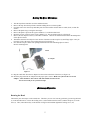
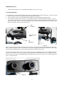
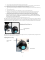
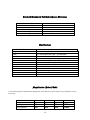
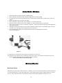
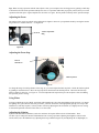
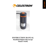
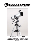
INSTRUCTION MANUAL
● Professional Model # 44108 ● Professional Model # 44110
Table of Contents
Care and Maintenance ……………………………………………………………………….
2
Professional Model # 44108 ………………………………………………………………….
3
Professional Model # 44110 ………………………………………………………………….
9
Warranty ……………………………………………………………………………………...
15
Introduction
Congratulations on your purchase of a Celestron microscope. Your microscope is a precision optical instrument, made of
the highest quality materials to ensure durability and long life. It is designed to give you a lifetime of pleasure with a
minimal amount of maintenance.
This instruction manual covers two different microscope models. Please be sure to locate your specific model of
microscope in order to ensure you read the correct information.
Before attempting to use your microscope, please read through the instructions to familiarize yourself with the functions
and operations to maximize your enjoyment and usage. See the microscope diagrams to locate the parts discussed in this
manual.
The microscopes described in this manual provide high powers from 40x up to 1500x. These microscopes types are ideally
suited for examining specimen slides of yeasts and molds, cultures, plant and animal parts, fibers, bacteria, etc.
Care and Maintenance
Your Celestron microscope is a precision optical instrument and should be treated with care at all times. Follow these care
and maintenance suggestions and your microscope will need very little maintenance throughout its lifetime.
•
•
•
•
•
•
•
•
•
•
•
•
•
•
When you are done using your microscope, remove any specimens left on the stage.
Turn off any electric illuminators.
Unplug any power cords being used.
Always place the dust cover over the microscope when not in use or when being stored.
Store the microscope in a dry and clean place.
Be very careful if using your microscope in direct sun light to prevent damage to the microscope or your eyes.
When moving your telescope, carry it by the “arm” with one hand and not by the focuser knobs, eyepiece housing,
etc. Then, put your other hand under the base for support.
Clean the outside surfaces (metal and plastics) with a moist cloth.
Always unplug any cords before cleaning.
Never clean optical surfaces with cloth or paper towels as they can scratch optical surfaces easily.
Blow off dust with a camels hair brush or an air blower from optical surfaces.
To clean fingerprints off of optical surfaces, use a lens cleaning agent and lens tissue available at most photo
outlets and when cleaning do not rub in circles as this may cause sleeks or scratches to occur.
Never disassemble or clean internal optical surfaces. This should be done by qualified technicians at the factory or
other authorized repair facilities.
When handling glass specimen slides, be careful as the edges can be sharp.
2
Professional Microscope – Model 44108
1. Head
2. Nosepiece
3. Objective
4. Specimen Stage
9. Stage Holder Clamp
5. Iris Diaphragm
8. Stage Movement Knobs
6. Illuminator
7. Coarse Focus Knob
Figure 1 Top & Bottom
18. Eyepiece
10. Locking Screw
17. Eyepiece Holder & Diopter
11. Arm
12. Tension Adjustment Ring
16. Iris Lever
13. Fine Focus Knob
15. Base
14. On/Off Switch
3
Standard Accessories Included with your Microscope
•
•
•
•
•
•
•
•
•
•
•
•
•
Two 10x Eyepieces
Two 15x Eyepieces
4x Objective Lens
10x Objective Lens
40x Objective Lens
100x Objective Lens
Electric Illuminator
Red, Blue, Green Color Filters
AC Adapter
Immersion Oil
5 Prepared Slides
Dust Cover
Extra Halogen Bulb 12V-15W
Specifications
Model # 44108
Stage
Head
Focuser
Objectives
Eyepieces
Interpupilliary Distance
Nosepiece
Illuminator
Condenser
Diaphragm
AC Adapter
Specifications
Mechanical Stage 132mm x 140mm
45° Inclined Binocular Head -- 360° Rotatable
Coaxial with Coarse and Fine Focus
Achromatic 4x, 10x, 40x, and 100x DIN 195mm
(2) 10x Wide Field -- 18mm Field of View
(2) 15x Wide Field -- 13mm Field of View
Adjustable from 55mm to 75mm
Quadruple with click stop
Built-in electric -- Halogen bulb 12Volt-15Watt
Abbe N.A. 1.25
Iris
115Volt-60Hz or Model with 230Volt-50Hz 12VDC-1500ma
Magnification (Power) Table
Use the following table to determine the magnification of the different eyepiece/objective lens combination of your
microscope.
Objective Lens
4x
10x
40x
100x
10x Eyepieces
40x
60x
100x
150x
400x
600x
1000x
1500x
15x Eyepieces
4
Setting Up Your Microscope
1.
2.
3.
4.
5.
6.
7.
8.
9.
Take the Styrofoam container out of the cardboard carton.
Remove the tape from the Styrofoam container holding the two sections together.
Carefully remove the microscope and other parts from the container and set them on a table, desk, or other flat
surface.
Remove the plastic bag covering the microscope.
Remove the plastic caps from the eyepiece holders (17) on the binocular head.
Insert the two 10x eyepieces in the eyepiece holders (17). They are held in place by a friction fit.
Remove the four objective lenses (3) from their containers. Unscrew the container lids from the threaded portion
of the objective lenses.
Thread the end of the 4mm objective lens into one of the holes on the nosepiece (2) until finger tight. It may be
necessary to lower the stage (4) by turning the coarse focus knob (7).
Now turn the nosepiece to the next opening and thread each of the remaining objective lenses
into the remaining holes.
Socket
AC Adapter
Figure 1a
10. Plug the small cable from the AC adapter into the socket on the back of the base (see Figure 1a).
11. Insert the plug end of the AC adapter into the proper power source. Make sure you have the correct AC
adapter – some models are 115-volt AC and other models are 230-volt AC
You are now ready to use your microscope!
Microscope Operation
Rotating the Head
The head of your microscope can be rotated 360°. Therefore you can view from any position by just moving the head
(1) to the desired location. Loosen the locking screw (10) located between the head (1) and the nosepiece (2) on the
arm (11). Then, rotate the head (1) to the desired viewing location and then tighten the locking screw (10).
5
Illumination Power
Turn the On/Off Switch (14) “On” and adjust the brightness to the level you want.
Viewing a Specimen
Your instrument is provided with a mechanical stage with a stage holder clamp and directional knobs –see figure 1b and 1c.
1. Use the clamp lever to open the clamping arm of the stage holder clamp (9).
2. Place a specimen slide (3” size) inside the holder and gently close the clamping arm against the slide.
3. Use the stage movement knobs (see Figure 1c) to position the specimen over the opening in the stage (4). The top
stage movement knob moves the X axis (forward and backward) whereas the bottom stage movement knob moves the
Y axis (side to side). Note: A vernier scale on both axes allows the exact marking and replication of an object in the
field of view that the user may want to come back to.
Abbe
Condenser
Stage Movement
Knobs
Iris
Diaphragm
Figure 1b
Figure 1c
Tip: To position the specimen directly under the objective lens, close the opening on the iris diaphragm (see Figure 1b)
until it is almost completely closed. You should see a small beam of light projected onto the specimen slide. Now simply
use the stage movement knobs (1c) to move the specimen directly inside the beam of light.
To achieve the best focus with your microscope, not only can you make adjustments with the coarse and fine focus knobs,
but you can also adjust the focus of each eyepiece (diopter adjustment (17) individually (your eyes are slightly different
from each other) as well as the interpupillary distance (distance between the center of your eyes). To achieve the sharpest
focus – see Figure 1d and:
Figure 1d
6
4. First, rotate each eyepiece diopter clockwise so that they are all the way down.
5. Change the distance between the eyepieces by sliding the eyepiece slide plate in or out horizontally. To adjust the slide plate,
grasp the knurled portion on each side of the plate. Do not hold the eyepieces to adjust the interpupillary distance.
6. With the 4x objective lens focus with one eye using the coarse and fine focus knobs.
7. Adjust the eyepiece side plate until the whole field of view can be observed through both eyes at the same time without having
to
8. move your head side to side.
9. Now read the number off of the eyepiece sliding plate scale. This is your interpupillary distance.
10. Depending on your individual eyes, you may need to make slight adjustments to the right and left eyepieces for the most
comfortable viewing. Move the diopter up or down until you have the specimen slide in sharp and comfortable focus.
11. You have started with the 4x objective (which is the lowest power objective) and work your way up to higher powers.
12. Look through the eyepiece while turning the coarse focus knob (7) until the specimen comes into view. You may
need to adjust the stage knobs (Figure 1c) slightly to center the specimen in the field of view. Warning: When focusing, be
careful not to raise the specimen stage so high that the specimen slide touches the objective lens. Not only can you break
your slide but you may scratch the objective lens.
13. Finally, adjust the fine focus knob (13) until you reach the sharpest focus for your eye.
Tip: When viewing a specimen with the 100x objective lens, you can improve the resolving power by placing a small drop
of immersion oil between the specimen and objective lens. For specimen slides that you prepare yourself, always cover the
specimen with a thin piece of glass and place the oil on the cover glass. Do not put the oil directly on the specimen sample.
Adjusting the Focus (Figure 1e)
Tension Adjustment
Ring
The tension of the coarse focus knob can be adjusted to be tighter or looser for your particular needs by moving the tension
ring clockwise or counterclockwise – see Figure 1e.
Adjusting the Focus Stop
Rack & Pinion
Screw
Limit Stop Knob
Figure 1f
7
To change the range of working distance of the stage (4) you need to adjust the limit stop knob. Unlock the limit stop knob
by pushing it counterclockwise. Move the stage upward or downward to the desired position. Then lock the limit-stop
knob by turning it clockwise– see Figure 1f. You will adjust the limit stop knob to prevent an objective lens from hitting
the specimen you are viewing.
Adjusting the Lighting
Specimens of different size, thickness, and color variations will require different levels of illumination. There are three
ways to change the amount of illumination when viewing a specimen; adjusting the brightness control on the on/off switch
(14), adjusting the Abbe condenser (Figure 1b) and adjusting the iris diaphragm (see Figure 1b):
1. When viewing a specimen that is not transparent or dark in color you may need to increase the amount of light to
resolve certain features or details. This is best done by simply increasing the brightness of the illuminator by
rotating the brightness control on the on/off switch (14) all the way to its highest setting.
2. When viewing with lower power (4x and 10x) objective lenses you will need to lower the condenser lens in order to
spread the light over the larger field of view. To change the position of the condenser, simply rotate the silver center
portion of the Iris diaphragm (1b) clockwise until the beam of light spreads wide enough to illuminate the entire field
of view when viewing.
3.
As you lower the condenser to spread out the light or change to a higher power objective lens, your image will
appear dimmer. Instead of increasing the light intensity of the illuminator (which may “wash out” fine detail of the
specimen you are viewing), open the aperture of the iris diaphragm to let in more light. Opening and closing the
diaphragm (with its lever) will give a relief view of the specimen and allow you to change the depth of field of the
specimen being viewed.
Using Filters
To bring out different levels of detail, experiment with changing the color of the back lighting of the specimen. To change
the lighting color, place the blue filter, the green filter, or the yellow filter into the filter holder which is on the bottom of
the iris diaphragm. Push the small lever on the bottom part of the iris diaphragm counterclockwise and you will be able to
see the holder. Drop a filter into the holder and rotate the filter holder back under the iris. You may need to
refocus by adjusting the fine focus knob (13) slightly for best viewing. You should experiment with each of the
colors to see the results. See Figure 1g.
Filter Holder
Figure 1g
Replacing the Illuminator Bulb
1.
2.
3.
4.
5.
6.
Make sure the power is off and then carefully lay the microscope on one side.
On the bottom of the microscope, locate and unlock (counterclockwise) the knurled knob that holds the bulb
compartment. See figure 1h.
Remove the knurled knob with the bulb and bulb socket. See Figure 1i.
Remove the old bulb from its socket but make sure beforehand that the bulb has cooled down before touching it.
Install the new bulb by pressing the prongs lightly into the socket.
Replace the bulb and bulb holder back into the base (15) by lining up the tabs and then turn clockwise to lock the
knob.
Figure 1h
Figure 1i
8
Professional Microscope – Model # 44110
1. Head
2. Nosepiece
3. Objective
9. Stage Holder Clamp
4. Specimen Stage
8. Condenser Regulator Knob
5. Iris Diaphragm
7. Coarse Focus Knob
6. Illuminator
Figure 2 Top & Bottom Images
18. Eyepiece
10. Locking Screw
17. Eyepiece Holder & Diopter
11. Arm
12. Tension Adjustment Ring
16. Condenser Adjustment Screws
13. Fine Focus Knob
14. On/Off Switch
15. Base
9
Standard Accessories Included with your Microscope
•
•
•
•
•
•
Two Plan 10x Eyepieces
Two Plan 15x Eyepieces
Plan 4x Objective Lens
Plan 10x Objective Lens
Plan 40x Objective Lens
Plan 100x Objective Lens
•
•
•
•
•
•
Electric Illuminator
Red, Blue, Green, White Color Filters
Power Cord
Immersion Oil
5 Prepared Slides
Dust Cover
Specifications
Model # 44110
Stage
Specifications
Mechanical Stage 132mm x 140mm
Head
Focuser
Objectives
Eyepieces
45° Inclined Binocular Head -- 360°Rotatable
Coaxial with Coarse and Fine Focus
Plan Achromatic 4x, 10x, 40x, and 100x -- DIN 195mm
(2) Plan 10x Wide Field -- 18mm Field of View
(2) Plan 15x Wide Field -- 13mm Field of View
Adjustable from 55mm to 75mm
Reversed Quadruple with click stop
Built-in electric Koehler System -- Halogen bulb 6Volt-20Watt
Achromatic Swing N.A. 1.2
Deluxe Iris
Universal 90volt to 240Volt -- 50/60 Hz
Interpupilliary Distance
Nosepiece
Illuminator
Condenser
Diaphragm
Power
Magnification (Power) Table
Use the following table to determine the magnification of the different eyepiece/objective lens combination of your
microscope.
Objective Lens
4x
10x
40x
100x
10x Eyepieces
40x
60x
100x
150x
400x
600x
1000x
1500x
15x Eyepieces
10
Setting Up Your Microscope
1.
2.
3.
4.
5.
6.
7.
8.
9.
Take the Styrofoam container out of the cardboard carton.
Remove the tape from the Styrofoam container holding the two sections together.
Carefully remove the microscope and other parts from the container and set them on a table, desk, or other flat
surface.
Remove the plastic bag covering the microscope.
Remove the plastic caps from the eyepiece holders (17) on the binocular head.
Insert the two 10x eyepieces in the eyepiece holders (17). They are held in place by a friction fit.
Remove the four objective lenses (3) from their containers. Unscrew the container lids from the threaded portion
of the objective lenses.
Thread the end of the 4mm objective lens into one of the holes on the nosepiece (2) until finger tight. It may be
necessary to lower the stage (4) by turning the coarse focus knob (7).
Now turn the nosepiece to the next opening and thread each of the remaining objective lenses
into the remaining holes.
Figure 2a
10. Plug the power cord into the socket on the back of the base (see Figure 2a).
11. Insert the prong end of the power cord into the proper power source. The electronics in this microscope work
anywhere in the world with its universal voltage of 90volt to 240volt.
You are now ready to use your microscope!
Microscope Operation
Rotating the Head
The head of your microscope can be rotated 360°. Therefore you can view from any position by just moving the head
(1) to the desired location. Loosen the locking screw (10) located between the head (1) and the nosepiece (2) on the
arm (11). Then, rotate the head (1) to the desired viewing location and then tighten the locking screw (10)
11
Illumination Power
Turn the On/Off Switch (14) “On” and adjust the brightness to the level you want.
Viewing a Specimen
Your instrument is provided with a mechanical stage with a stage holder clamp and directional knobs.
1. Use the clamp lever to open the clamping arm of the stage holder clamp (9).
2. Place a specimen slide (3” size) inside the holder and gently close the clamping arm against the slide
3. Use the stage movement knobs (see bottom right of Figure 2b) to position the specimen over the opening in the stage (4). The top
stage movement knob moves the X axis (forward and backward) whereas the bottom stage movement knob moves the Y axis (side
to side). Note: A vernier scale on both axes allows the exact marking and replication of an object in the field of view that the user
may want to come back to.
Swing Condenser
in the center of
stage
Stage Movement Knob
on the right side
Figure 2b
Tip: To position the specimen directly under the objective lens, close the opening on the illuminator by turning it counterclockwise until
it is almost completely closed. You should see a small beam of light projected onto the specimen slide. Now simply use the stage
movement knobs (2b) to move the specimen directly inside the beam of light.
To achieve the best focus with your microscope, not only can you make adjustments with the coarse and fine focus knobs, but you can
also adjust the focus of each eyepiece (diopter adjustment (17) individually (your eyes are slightly different from each other) as well as
the interpupillary distance (distance between the center of your eyes). To achieve the sharpest focus – see Figure 2c and:
Figure 2c
4. First rotate each eyepiece diopter clockwise so that they are all the
way down.
5. Change the distance between the eyepieces by sliding the eyepiece
slide plate in or out horizontally. To adjust the slide plate, grasp
the knurled portion on each side of the plate. Do not hold the
eyepieces to adjust the interpupillary distance.
6. With the 4x objective lens focus with one eye using the coarse and
fine focus knobs.
7. Adjust the eyepiece side plate until the whole field of view can be
observed through both eyes at the same time without having to
move your head side to side.
8. Now read the number off of the eyepiece sliding plate scale. This is your interpupillary distance.
9. Depending on your individual eyes, you may need to make slight adjustments to the right and left eyepieces for the most
comfortable viewing. Move the diopter up or down until you have the specimen slide in sharp and comfortable focus.
10. You have started with the 4x objective (which is the lowest power) and work your way up to higher powers.
11. Look through the eyepiece while turning the coarse focus knob (7) until the specimen comes into view. You may
need to adjust the stage knobs (Figure 2b) slightly to center the specimen in the field of view. Warning: When
focusing, be careful not to raise the specimen stage so high that the specimen slide touches the objective lens.
Not only can you break your slide but you may scratch the objective lens.
12. Finally, adjust the fine focus knob (13) until you reach the sharpest focus for your eye.
12
Tip: When viewing a specimen with the 100x objective lens, you can improve the resolving power by placing a small drop
of immersion oil between the specimen and objective lens. For specimen slides that you prepare yourself, always cover the
specimen with a thin piece of glass and place the oil on the cover glass. Do not put the oil directly on the specimen sample.
Adjusting the Focus
The tension of the coarse focus knob can be adjusted to be tighter or looser for your particular needs by moving the tension
ring clockwise or counterclockwise – see Figure 2d.
Tension Adjustment
Ring
Figure 2d
Adjusting the Focus Stop
Rack &
PinionScrew
Limit Stop Knob
Figure 2e
To change the range of working distance of the stage (4) you need to adjust the limit stop knob. Unlock the limit stop knob
by pushing it counterclockwise. Move the stage upward or downward to the desired position. Then lock the limit-stop
knob by turning it clockwise– see Figure 2e. You will adjust the limit stop knob to prevent an objective lens from hitting
the specimen you are viewing.
Using Filters
To bring out different levels of detail, experiment with changing the color of the back lighting of the specimen. To change
the lighting color, place the blue filter, the green filter, yellow or white filter in the light path by placing one on top of the
illuminator (it will drop in place). You may need to refocus by adjusting the fine focus knob (13) slightly for best viewing.
You should experiment with each of the colors to see the results.
Adjusting the Lighting
Specimens of different size, thickness, and color variations will require different levels of illumination. There
are three ways to change the amount of illumination when viewing a specimen; adjusting the brightness control on the
on/off switch (14) or the illuminator (6), adjusting the Swing condenser (Figure 2b), and adjusting the iris diaphragm (5).
13
1.
When viewing a specimen that is not transparent or dark in color you may need to increase the amount of light to
resolve certain features or details. This is best done by simply increasing the brightness of the illuminator by
rotating the brightness control on the on/off switch (14) all the way to its highest setting or rotate the illuminator in the clockwise
direction.
2. When viewing with lower power (4x and 10x) objective lenses you will need to lower the condenser lens in order to
spread the light over the larger field of view. To change the position of the condenser, simply rotate the condenser regulator knob
(8) clockwise until the beam of light spreads wide enough to illuminate the entire field of view when viewing.
3.
As you lower the condenser to spread out the light or change to a higher power objective lens, your image will appear dimmer.
Instead of increasing the light intensity of the illuminator (which may “wash out” fine detail of the specimen you are viewing),
open the aperture of the iris diaphragm to let in more light. Opening and closing the diaphragm (with its knurled ring) will give a
relief view of the specimen and allow you to change the depth of field of the specimen being viewed. The iris diaphragm knurled
ring (see Figure 2f) has a scale with an indicator showing what the N.A. of the diaphragm is.
Figure 2f
Swing Condenser
Iris Scale
Condenser Adjustment Centering Screws
Illuminator
4.
5.
6.
7.
For low powers (4x and 10x objectives), you should keep the swing condenser (see Figure 2f) in the light path. However, for
higher powers (40x and 100x objectives), you can turn the condenser knob clockwise to move it out of the light path.
Use the condenser adjustment centering screws (see Figure 2f) to put the specimen image in the center of the field of view. When
the shadow around the field of view of the eyepiece is symmetrical, it shows the condenser has been centered correctly. In fact,
you can enlarge the field diaphragm and make the image tangent to the field of view.
You can adjust the field diaphragm to prevent extraneous light from entering the light path and this limits the diameter of the light
beam entering the condenser. When the image of the diaphragm is just on the edge of the field of view, you can obtain the clearest
image.
The iris scale can be used to help obtain the best resolution and contrast. You will try to match as best you can the N.A. of
illumination with the N.A. of the objective being used. Normally you would put the N.A. of the condenser to 80% of the objective
N.A. For example, the 40x objective has an N.A. of 0.65 which would indicate that you would set the scale on the iris diaphragm
to 0.52 (0.65 x 0.80 = 0.52).
Replacing the Illuminator Bulb and Fuses
1.
2.
3.
4.
5.
6.
7.
Make sure the power is off and carefully lay the microscope on one side.
On the bottom of the microscope, locate and unlock (counter clockwise) the knurled knob that holds the bulb compartment.
See figure 1h.
Remove the knurled knob with the bulb and bulb socket. See Figure 2g.
Remove the old bulb from its socket but make sure beforehand that the bulb has cooled down before touching it.
Install the new bulb by pressing the prongs lightly into the socket.
Replace the bulb and its holder back into the base (15) by lining up the tabs and turning clockwise to lock.
Two fuses are located in the back of the microscope (see Figure 2a). They are 15A T3 fuses. If the power does not come on, it
is possible that one or both fuses needs to be replaced. Make sure all power the power is off and then use a flat head
screwdriver to remove the fuses. If they are blown out, replace them with new fuses and then install the fuse box back in place.
Figure 2g
14
Celestron Two Year Warranty
A.
Celestron warrants this microscope to be free from defects in materials and workmanship for two years. Celestron will repair or replace such
product or part thereof which, upon inspection by Celestron, is found to be defective in materials or workmanship. As a condition to the obligation of
Celestron to repair or replace such product, the product must be returned to Celestron together with proof-of-purchase satisfactory to Celestron.
B.
The Proper Return Authorization Number must be obtained from Celestron in advance of return. Call Celestron at (310) 328-9560 to receive the
number to be displayed on the outside of your shipping container.
All returns must be accompanied by a written statement setting forth the name, address, and daytime telephone number of the owner, together with a
brief description of any claimed defects. Parts or product for which replacement is made shall become the property of Celestron.
The customer shall be responsible for all costs of transportation and insurance, both to and from the factory of Celestron, and shall be
required to prepay such costs.
Celestron shall use reasonable efforts to repair or replace any microscope covered by this warranty within thirty days of receipt. In the event repair
or replacement shall require more than thirty days, Celestron shall notify the customer accordingly. Celestron reserves the right to replace any
product which has been discontinued from its product line with a new product of comparable value and function.
This warranty shall be void and of no force of effect in the event a covered product has been modified in design or function, or subjected to
abuse, misuse, mishandling or unauthorized repair. Further, product malfunction or deterioration due to normal wear is not covered by
this warranty.
CELESTRON DISCLAIMS ANY WARRANTIES, EXPRESS OR IMPLIED, WHETHER OF MERCHANTABILITY OF FITNESS FOR A
PARTICULAR USE, EXCEPT AS EXPRESSLY SET FORTH HEREIN.
THE SOLE OBLIGATION OF CELESTRON UNDER THIS LIMITED WARRANTY SHALL BE TO REPAIR OR REPLACE THE COVERED
PRODUCT, IN ACCORDANCE WITH THE TERMS SET FORTH HEREIN. CELESTRON EXPRESSLY DISCLAIMS ANY LOST PROFITS,
GENERAL, SPECIAL, INDIRECT OR CONSEQUENTIAL DAMAGES WHICH MAY RESULT FROM BREACH OF ANY WARRANTY, OR
ARISING OUT OF THE USE OR INABILITY TO USE ANY CELESTRON PRODUCT. ANY WARRANTIES WHICH ARE IMPLIED AND
WHICH CANNOT BE DISCLAIMED SHALL BE LIMITED IN DURATION TO A TERM OF TWO YEARS FROM THE DATE OF
ORIGINAL RETAIL PURCHASE.
Some states do not allow the exclusion or limitation of incidental or consequential damages or limitation on how long an implied warranty lasts, so
the above limitations and exclusions may not apply to you.
This warranty gives you specific legal rights, and you may also have other rights which vary from state to state.
Celestron reserves the right to modify or discontinue, without prior notice to you, any model or style microscope.
If warranty problems arise, or if you need assistance in using your microscope contact:
Celestron
Technical Support Department
2835 Columbia Street
Torrance, CA 90503 U.S.A.
Tel. (310) 328-9560
Fax. (310) 212-5835
www.celestron.com
Monday-Friday 8AM-4PM PST
This warranty supersedes all other product warranties.
NOTE: This warranty is valid to U.S.A. and Canadian customers who have purchased this product from an Authorized Celestron Dealer in
the U.S.A. or Canada. Warranty outside the U.S.A. and Canada is valid only to customers who purchased from a Celestron Distributor or
Authorized Celestron Dealer in the specific country and please contact them for any warranty service.
15
Celestron
2835 Columbia Street
Torrance, Ca 90503 U.S.A.
Tel. 310-328-9560
Fax. 310-212-5835
Web www.celestron.com
Copyright 2007
All rights reserved
Products or instructions may change
without notice or obligation.
Printed in China
$ 10.00
04-07