1
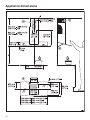
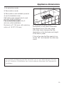
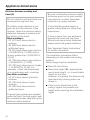
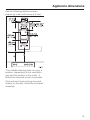
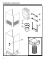
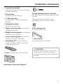
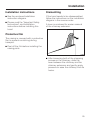
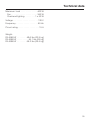
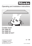
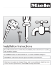
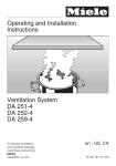
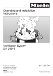
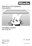
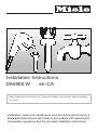
Installation Instructions
DA5960 W
en-CA
Read these instructions and the "Important Safety Instructions" before installing
this hood.
Installation, repair and maintenance work should be performed by a
Miele authorized service technician in accordance with national and
local safety regulations and the provided installation instructions.
Caring for the environment
Disposal of packing material
Disposal of an old appliance
The cardboard box and packing
materials protect the appliance during
shipping. They have been designed to
be biodegradable and recyclable.
Please recycle.
Old appliances may contain materials
that can be recycled. Please contact
your local recycling center about the
possibility of recycling these materials.
,DANGER
Ensure that any plastic wrappings,
bags, etc., are disposed of safely
and kept out of the reach of babies
and young children. Danger of
suffocation!
Before discarding an old appliance,
disconnect it from the electrical
supply and cut off the power cord to
prevent it from becoming a hazard.
21
Appliance dimensions
22
Appliance dimensions
dai2479
1) Air extraction mode
2) Recirculation mode
3) Recirculation vent installed upwards
4) and 5) Installation area
Wall/ceiling area respectively for vent
hole and outlet installation.
For recirculation mode only 4)
and only outlet installation.
Ductwork ø 6" (150 mm), with reducing
colla r ø 4 15/16" (125 mm)
6) If you plan to have a tiled
backsplash or wall panel underneath
the exhaust hood, this may cause
difficulties when changing the filter,
depending on the thickness and height
of the tiles or panel.
If this is the case the filter needs to be
turned 180° and inserted the other way
round.
Les appareils de Miele peuvent être encastrés à ras ou avec débordement. Discutez
de vos conditions d'installation avec votre architecte, décorateur de l'intérieure et
installateur.
23
Appliance dimensions
Distance between cooktop and
hood (S)
Do not install this exhaust hood over
cooktops burning solid fuel.
Provided a larger distance is not
given by the manufacturer of the
cooktop, follow the minimum safety
distances between a cooktop and
the bottom of the hood:
Miele cooktops:
- 24" (610 mm) above electric
surfaces,
- 26" (660 mm) above electric
grill/boiler/fryers,
- 24" (610 mm) above gas surfaces
ß 25,000 BTU's (7.5 kW) and no
burner greater than 10,250 BTU's
(3 kW) ,
- 30" (762 mm) above gas surfaces
> 25,000 BTU's (7.5 kW),
- 30" (762 mm) above burner heads
> 10,250 BTU's (3 kW). For
example, a Wok used separately
or in combination with a cooktop.
Non-Miele cooktops:
- 24" (610 mm) above all electric
surfaces,
- 30" (762 mm) above all gas
surfaces,
- 26" (660 mm) above electric
grill/boiler/fryers.
If several gas surfaces are installed
under the hood, the total output must
be considered when determining the
minimum safety distance.
24
Be sure to follow the minimum safety
distances given by the gas cooktop
manufacturer to easily flammable
materials e.g. upper cabinets.
If local building codes require a
greater safety distance, follow their
requirement.
If there is more than one appliance
beneath the hood and they have
different minimum safety distances
always select the greater distance.
See "Important Safety Instructions"
for further information.
The installation procedure differs
depending on the model and venting
method.
Before beginning the installation:
^ Read all instructions.
^ Determine height (S), regarding the
user’s body height, i.e. a comfortable
height for the user.
However, the greater the distance the
less effectively cooking odors are
drawn in.
^ If the hood is fitted flush to the
ceiling, regard the possible unit
height when selecting the installation
height.
Appliance dimensions
Use the following distances when
preparing a rear wall (screw ø 5 mm).
*The middle retaining plate can vary in
position, depending on the ventilation
gap and the position of the outlet. It
should be mounted as low as possible.
If the exhaust hood is being mounted
directly on the wall, follow the enclosed
assembly.
25
Installation accessories
dai2417
26
Installation accessories
a 3 protective shields
to prevent scratches to the chimney
during installation.
b 2 hose clips
for securing the ducting.
8 large headed screws 5 x 40 mm
for securing the retaining plates and the
canopy
c 1 reducing collar
for use with 5" (125 mm) exhaust
ducting.
(S8 wall anchors included in the
packaging are not for use in USA)
d 2 protective strips
for chimney mounting
e Upper retaining plate secures the
chimney extension
2 M 6 locking nuts
for securing the unit
f Middle retaining plate for additional
stability of the chimney
g Lower retaining plate secures the
canopy and motor assembly.
h Installation kit for recirculation
mode; contains diverter and hose
(optional accessory)
1 allen wrench
for adjusting the unit height
,CAUTION
1 lever for dismantling the chimney
To avoid risk of hand or other injury,
avoid contact with sharp edges
during the assembly and installation
process.
Installation instruction diagram
27
Plywood backing
The majority of the weight of the
installed ventilation system will be
supported by the lower retaining
plate. It must be firmly attached to
the stud framing behind the drywall.
If studs are not available in the
required locations, a plywood
backing (min. ½" (13 mm) thick)
spanning at least two studs must be
installed. Failure to adequately
support the weight as stated may
result in the ventilation system falling
off the wall, causing personal injury
and property damage.
(If plywood backing is not needed,
proceed to the included "Installation
diagram".)
To install a plywood backing
^ Determine and mark the location of
the retaining plate for the canopy as
outlined on the "Installation diagram".
^ Make a cutting line 3" (76 mm) above
and 3" (76 mm) below the outline of
the retaining plate.
28
^ Find the studs to the left and right of
the mounting location by tapping the
wall or using a stud finder.
^ Mark a vertical cutting line along the
center of each stud.
,CAUTION
When cutting or drilling into the wall
or ceiling, do not damage electrical
wiring and other hidden utilities.
^ Remove the drywall between the
cutting lines and replace it with
plywood of a matching thickness
(min. ½" (13 mm) thick). Tape the
joints and refinish the wall.
^ Proceed to the enclosed "Installation
diagram" to complete the installation.
Installation
Installation instructions
Dismantling
^ See the enclosed installation
instruction diagram.
If the hood needs to be disassembled,
follow the instructions on the installation
diagram in the reverse order.
^ Please read the "Important Safety
Instructions" and Installation
instructions before installing this
hood.
A lever is enclosed for easier removal
of the chimney extension.
Protective film
The casing is covered with a protective
film to prevent scratching during
transport.
^ Peel off the film before installing the
casing parts.
^ After loosening both of the clamping
screws on the chimney, slide the
lever between the chimney and the
chimney extension and gently apply
pressure to ease the chimney from its
hooks.
29
Air extraction
,WARNING
Danger of toxic fumes.
Gas cooking appliances release
carbon monoxide that can be
harmful or fatal if inhaled.
To reduce the risk of fire and to
properly exhaust air, the exhaust
gases extracted by the hood
should be vented outside of the
building only.
Do not vent exhaust air into
spaces within walls or ceilings or
in attics, crawl spaces or garages.
To reduce the risk of fire, only use
metal ductwork.
Please read and follow the
"IMPORTANT SAFETY
INSTRUCTIONS" to reduce the risk of
personal injury. Follow all local building
codes when installing the hood.
30
Exhaust ducting and connections
– The ducting should be as short and
straight as possible, and the number
of sharp bends should be minimized.
– For most efficient air extraction, the
diameter of the ductwork should not
be less than 6" (150 mm). Use of flat
ducts also reduces the air extraction
efficiency.
– Noise levels of the hood will increase
if flat ducts or round ducts of less
than 6" (150 mm) in diameter are
used.
– Use smooth or flexible pipes made
from approved non-flammable
materials for exhaust ducting.
– Where the ductwork is horizontal, it
must slope away from the hood at
least 1/8" per foot (1 cm per meter) to
prevent condensation dripping into
the appliance.
– If the exhaust is ducted through an
outside wall, a Telescopic Wall Vent
can be used.
Air extraction
Condensate trap
optional accessory
In some cases, a condensate trap may
also be required to collect and
evaporate any condensate which may
occur. This optional accessory is
available for ducts 5" (125 mm) and 6"
(150 mm) in diameter.
– If the exhaust is ducted into an
inactive flue, the air must be expelled
parallel to the flow direction of the
flue.
Never connect an exhaust hood to
an active chimney, dryer vent, flue,
or room venting ductwork. Seek
professional advice before
connecting an exhaust hood vent to
an existing, inactive chimney or vent
flue.
^ When installing a condensate trap,
ensure that it is positioned vertically
and if possible directly above the
exhaust outlet.
Important
If the ductwork runs through rooms,
ceilings, garages, etc. where
temperature variations exist, it may
need to be insulated to reduce
condensation.
31
Electrical connection
,WARNING
TO REDUCE THE RISK OF
FIRE, ELECTRIC SHOCK, OR
INJURY TO PERSONS,
OBSERVE THE FOLLOWING:
All electrical work should be
performed by a qualified electrician
in strict accordance with national
regulations (for USA: ANSI-NFPA 70)
and local safety regulations.
Installation, repairs and other work
by unqualified persons could be
dangerous.
Ensure that power to the appliance
is OFF while installation or repair
work is performed.
^ Verify that the voltage, load and
circuit rating information found on the
data plate (located behind the
grease filter), match the household
electrical supply before installing the
hood.
^ Use only with ventilation hood
cord-connection kits that have been
investigated and found acceptable
for use with this model hood.
If there is any question concerning the
electrical connection of this appliance
to your power supply, please consult a
licensed electrician or contact Miele’s
Technical Service Department.
,WARNING:
THIS APPLIANCE MUST BE
GROUNDED
32
Grounding Instructions
(USA and Mexico only)
This appliance must be grounded. In
the event of an electrical short circuit,
grounding reduces the risk of electric
shock by providing a path of least
resistance. This appliance is equipped
with a cord having a grounding wire
with a grounding plug. The plug must
be plugged into an outlet that is
properly installed and grounded.
WARNING - Improper grounding can
result in a risk of electric shock.
If there is any doubt, have the electrical
system of the house checked by a
qualified electrician.
Do not use an extension cord. If the
power supply cord is too short, have a
qualified electrician install an outlet
near the appliance.
Important (USA and Mexico only)
The hood comes equipped with a 4 ft
(1.2 m) power cord with a NEMA 5-15
molded plug for connection to a
120 VAC, 60 Hz, 15 A power outlet.
Important (Canada only)
To increase security before the
machine is installed, it is
recommended to install a protective
switch (30 mA).
Important (Canada only)
The hood must be hard wired
accordingly:
Black/Red wire: connect to L1 (live)
White wire: connect to N (neutral)
Green wire: connect to GND (ground)
Technical data
Maximum load . . . . . . . . . . . . . . 400 W
Fan . . . . . . . . . . . . . . . . . . . . . . 350 W
Overhead lighting . . . . . . . . . 1 x 50 W
Voltage . . . . . . . . . . . . . . . . . . . . . 120 V
Frequency . . . . . . . . . . . . . . . . . . 60 Hz
Circuit rating. . . . . . . . . . . . . . . . . . 15 A
Weight:
DA 5960 W . . . . . . . . 49.6 lbs (22.5 kg)
DA 5980 W . . . . . . . . . . 55.1 lbs (25 kg)
DA 5990 W . . . . . . . . 56.2 lbs (25.5 kg)
33
Alteration rights reserved / 1209
For the most updated manual see the Miele web site.
M.-Nr. 07 598 240 / 00