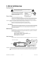
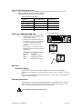
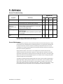
1
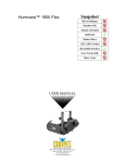
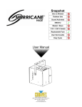
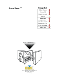
Snapshot
Data Stream™ 4
OK on Dimmer
Outdoor OK
Sound Activated
DMX512
Master/Slave
115V/230V Switch
Replaceable Fuse
User Serviceable
Duty Cycle
USER MANUAL
5200 NW 108th Avenue, Sunrise, FL 33351 U.S.A.
(800) 762-1084 – (954) 929-1115
FAX (954) 929-5560
www.chauvetlighting.com
TABLE OF CONTENTS
1. Before You Begin ............................................................................................................................................................. 3
WHAT IS INCLUDED ............................................................................................................................................................................... 3
UNPACKING INSTRUCTIONS .................................................................................................................................................................... 3
AC POWER........................................................................................................................................................................................... 3
SAFETY INSTRUCTIONS .......................................................................................................................................................................... 3
2. Introduction ...................................................................................................................................................................... 4
FEATURES ............................................................................................................................................................................................ 4
PRODUCT OVERVIEW ............................................................................................................................................................................ 4
3. Setup & Operation ........................................................................................................................................................... 5
FUSE REPLACEMENT ............................................................................................................................................................................. 5
FIXTURE LINKING .................................................................................................................................................................................. 5
Data Cabling ................................................................................................................................................................. 5
DMX DATA CABLE ................................................................................................................................................................................ 5
CABLE CONNECTORS ............................................................................................................................................................................ 5
3-PIN TO 5-PIN CONVERSION CHART ...................................................................................................................................................... 6
SETTING UP A DMX SERIAL DATA LINK ................................................................................................................................................... 6
MOUNTING ........................................................................................................................................................................................... 6
Orientation & Rigging .................................................................................................................................................... 6
OPERATING INSTRUCTIONS .................................................................................................................................................................... 6
5. Appendix........................................................................................................................................................................... 7
GENERAL TROUBLESHOOTING ................................................................................................................................................................ 7
GENERAL MAINTENANCE ....................................................................................................................................................................... 7
RETURNS PROCEDURE .......................................................................................................................................................................... 8
CLAIMS ................................................................................................................................................................................................ 8
CONTACT US ........................................................................................................................................................................................ 8
TECHNICAL SPECIFICATIONS .................................................................................................................................................................. 9
Date Stream™ 4 User Manual
2
2/8/2012 5:06 PM
1. BEFORE YOU BEGIN
What Is Included
Ø
Ø
Ø
Ø
1 x Data Stream™ 4
Power Cord
Warranty Card
User Manual
Unpacking Instructions
Immediately upon receiving a fixture, carefully unpack the carton, check the contents to ensure that
all parts are present, and have been received in good condition. Notify the shipper immediately and
retain packing material for inspection if any parts appear damaged from shipping or the carton itself
shows signs of mishandling. Save the carton and all packing materials. In the event that a fixture
must be returned to the factory, it is important that the fixture be returned in the original factory box
and packing.
AC Power
This fixture has an auto-switching power supply that can accommodate a wide range of input
voltages. The only thing necessary to do before powering on the unit is to make sure the line voltage
you are applying is within the range of accepted voltages. This fixture will accommodate between
100V and 240V AC 50-60 Hz. All fixtures must be powered directly off a switched circuit and cannot
be run off a rheostat (variable resistor) or dimmer circuit, even if the rheostat or dimmer channel is
used solely for a 0% to 100% switch.
Warning!
Verify that the voltage on your unit matches the line voltage applied. Damage to
your fixture may result if the line voltage applied does not match the voltage
indicated on the product. All fixtures must be connected to circuits with a suitable
Earth Ground.
Safety Instructions
Please read these instructions carefully, which includes important
information about the installation, usage and maintenance of this
product.
·
·
·
·
·
·
·
·
·
·
·
Caution!
Please keep this User Guide for future consultation. If you sell the unit to another user, be sure that
they also receive this instruction booklet.
Always make sure that you are connecting to the proper voltage, and that the line voltage you are
connecting to is not higher than that stated on the decal or rear panel of the fixture.
This product is intended for indoor use only!
To prevent risk of fire or shock, do not expose fixture to rain or moisture. Make sure there are no
flammable materials close to the unit while operating.
The unit must be installed in a location with adequate ventilation, at least 20in (50cm) from adjacent
surfaces. Be sure that no ventilation slots are blocked.
Secure fixture to fastening device using a safety chain. Never carry the fixture solely by its head. Use
its carrying handles.
Maximum ambient temperature (Ta) is 104°F (40°C). Do not operate fixture at temperatures higher
than this.
In the event of a serious operating problem, stop using the unit immediately. Never try to repair the
unit by yourself. Repairs carried out by unskilled people can lead to damage or malfunction. Please
contact the nearest authorized technical assistance center. Always use the same type spare parts.
Never connect the device to a dimmer pack.
Make sure the power cord is never crimped or damaged.
Never disconnect the power cord by pulling or tugging on the cord.
There are no user-serviceable parts inside the unit. Do not open the housing or
attempt any repairs yourself. In the unlikely event your unit may require service,
please contact CHAUVET® at: 954-929-1115.
Date Stream™ 4 User Manual
3
2/8/2012 5:06 PM
2. INTRODUCTION
Features
·
·
·
·
·
Universal DMX-512 optical splitter
One input to four outputs (3-pin and 5-pin)
Additional thru output (3-pin and 5-pin)
Electrical isolation between input and output
1-space (1U) rack mount
Product Overview
Link out/
DMX through
DMX In
3 & 5-pin
FRONT VIEW
DMX
signal
indicator
Power
indicator
Ears for
rackmount
13mm
mounting/clamp
location
Fuse
Power input
cable
REAR VIEW
Date Stream™ 4 User Manual
4
2/8/2012 5:06 PM
3. SETUP & OPERATION
Fuse Replacement
Disconnect the power cord before replacing a fuse and always
replace with the same type fuse.
With a flat-head screwdriver, unscrew the fuse
holder from its housing. Remove the damaged
fuse from its holder and replace with exact
same type fuse. Screw the fuse holder back in
its place and reconnect power.
The fuse is located
inside this
compartment.
Remove using a flat
head screwdriver.
FUSE
Fixture Linking
You will need a serial data link to run light
shows of one or more fixtures using a DMX-512 controller or to run synchronized shows on two or
more fixtures set to a master/slave operating mode. The combined number of channels required by
all the fixtures on a serial data link determines the number of fixtures the data link can support.
Important: Fixtures on a serial data link must be daisy chained in one single line. To comply with the EIA-485
standard, no more than 32 devices should be connected on one data link.
Maximum recommended serial data link distance: 500 meters (1640 ft.)
Maximum recommended number of fixtures on a serial data link: 32 fixtures
Data Cabling
To link fixtures together you must obtain data cables. You can purchase CHAUVET ®-certified DMX
cables directly from a dealer/distributor or construct your own cable. If you choose to create your own
cable please use data-grade cables that can carry a high quality signal and are less prone to
electromagnetic interference.
DMX Data Cable
Use a Belden© 9841 or equivalent cable which meets the specifications for EIA RS-485 applications.
Standard microphone cables cannot transmit DMX data reliably over long distances. The cable will
have the following characteristics:
2-conductor twisted pair plus a shield
Maximum capacitance between conductors – 30 pF/ft.
Maximum capacitance between conductor and shield – 55 pF/ft.
Maximum resistance of 20 ohms/1,000 ft.
Nominal impedance 100 – 140 ohms
Cable Connectors
Cabling must have a male XLR connector on one end and a female XLR connector on the other end.
1
3
2
DMX connector configuration
COMMON
INPUT
1
3
2
CAUTION
1
3
2
DMX +
DMX
-
Resistance 120
ohm 1/4w between
pin 2 (DMX -) and
pin 3 (DMX +) of
the last fixture.
OUTPUT
Termination reduces signal errors. To
avoid signal transmission problems
and interference, it is always
advisable to connect a DMX signal
terminator.
Do not allow contact between the common and the fixture’s chassis ground. Grounding the common
can cause a ground loop, and your fixture may perform erratically. Test cables with an ohm meter to
verify correct polarity and to make sure the pins are not grounded or shorted to the shield or each
other.
Date Stream™ 4 User Manual
5
2/8/2012 5:06 PM
3-Pin to 5-Pin Conversion Chart
Note!
If you use a controller with a 5 pin DMX output connector, you will need to use a 5 pin to 3 pin
adapter. CHAUVET® Model No: DMX5M, or DMX5F.
The chart below details a proper cable conversion:
3 PIN TO 5 PIN CONVERSION CHART
Conductor
3 Pin Female (output)
5 Pin Male (Input)
Ground/Shield
Pin 1
Pin 1
Data ( - ) signal
Pin 2
Pin 2
Data ( + ) signal
Pin 3
Pin 3
Do not use
Do not use
Do not use
Do not use
Universal DMX Controller
Setting up a DMX Serial Data Link
1. Connect the (male) 3 pin connector side of
the DMX cable to the output (female) 3 pin
connector of the controller.
2. Connect the end of the cable coming from
the controller which will have a (female) 3
pin connector to the input connector of the
next fixture consisting of a (male) 3 pin
connector.
3. Then, proceed to connect from the output
as stated above to the input of the following
fixture and so on.
CHAUVET® Certified DMX Data Cables
Order Code
Description
DMX1.5
DMX Cable 1.5m/4.9ft
DMX4.5
DMX Cable 4.5m/14.8ft
DMX10
DMX Cable 10m/32.8ft
Mounting
Orientation & Rigging
This fixture may be mounted in any position provided there is adequate room for ventilation.
It is important never to obstruct the vents pathway. Mount the fixture using, a suitable “C” or “O” type
clamp.
Never mount in places where the fixture will be exposed to rain, high humidity, extreme temperature
changes or restricted ventilation.
Operating Instructions
This is DMX splitter, and it is designed to distribute/boost the incoming DMX signal into 4 separate
outputs. Each of the 4 outputs is electronically isolated from the others (with the exception of the
“thru” or “link” output) and each output has 3- and 5-pin XLR sockets.
Follow all DMX standards when using this device.
Date Stream™ 4 User Manual
6
2/8/2012 5:06 PM
5. APPENDIX
General Troubleshooting
Applies to
Symptom
Solution(s)
Lights
Foggers
& Snow
Controllers
Dimmers
& Chaser
Chase is too slow
Check user manual for speed adjustment
ü
ü
ü
Device has no power
Check for power on Mains.
Check device’s fuse. (internal and/or external)
ü
ü
ü
Fixture is on but
there is no
movement to the
audio
Make sure you have the correct audio mode on the
control switches. If audio provided via ¼” jack, make
sure a live audio signal exists
Adjust sound sensitivity knob
ü
ü
ü
Loss of signal
Use only DMX cables
Install terminator
Note: Keep DMX cables separated from power cables
or black lights.
ü
ü
ü
ü
Make sure connector is firmly connected to device
ü
ü
Remote does not
work
If you still have a problem after trying the above solutions, please contact CHAUVET®
Technical Support at the location on the next page.
General Maintenance
To maintain optimum performance and minimize wear fixtures should be cleaned frequently. Usage
and environment are contributing factors in determining frequency. As a general rule, fixtures should
be cleaned at least twice a month. Dust build up reduces light output performance and can cause
overheating. This can lead to reduced lamp life and increased mechanical wear. Be sure to power off
fixture before conducting maintenance.
Unplug fixture from power. Use a vacuum or air compressor and a soft brush to remove dust
collected on external vents and internal components. Clean all glass when the fixture is cold with a
mild solution of glass cleaner or Isopropyl Alcohol and a soft lint free cotton cloth or lens tissue. Apply
solution to the cloth or tissue and drag dirt and grime to the outside of the lens. Gently polish optical
surfaces until they are free of haze and lint.
The cleaning of internal and external optical lenses and/or mirrors must be carried out periodically to
optimize light output. Cleaning frequency depends on the environment in which the fixture operates:
damp, smoky or particularly dirty surrounding can cause greater accumulation of dirt on the unit’s
optics. Clean with soft cloth using normal glass cleaning fluid. - Always dry the parts carefully. - Clean
the external optics at least every 20 days. Clean the internal optics at least every 30/60 days.
Date Stream™ 4 User Manual
7
2/8/2012 5:06 PM
Returns
Procedure
The user must send the merchandise prepaid, in the original box, and with its original packing
and accessories. CHAUVET® will not issue call tags.
Call CHAUVET® and request a Return Merchandise Authorization (RMA) number before
shipping the product. Be prepared to provide the model number, serial number, and a brief
description of the cause for the return.
The user must clearly label the package with an RMA number. CHAUVET® will refuse any
product returned without an RMA number.
DO NOT write the RMA number directly on the box. Instead, write it on a properly
affixed label.
Once you have received the RMA number please include the following information on a piece
of paper inside the box:
· Your name
· Your address
· Your phone number
· The RMA number
· A brief description of the problem
Be sure to pack the product properly. Any shipping damage resulting from inadequate
packaging will be the customer’s responsibility. As a suggestion, proper FedEx packing or
double boxing are recommended.
CHAUVET® reserves the right to use its own discretion to repair or replace returned
product(s).
Claims
The carrier is responsible for any damage incurred during shipping to this product or any part
that shipped with it. Therefore, if the received merchandise appears to have damages caused
during shipping, the customer must submit the damage report and any related claims with the
carrier, not CHAUVET®. The customer must submit the report upon reception of the
damaged merchandise. Failure to do so in a timely manner may invalidate the customer’s
claim with the carrier.
For other issues such as missing components or parts, damage not related to shipping, or
concealed damage, the customer must make claims to CHAUVET® within seven (7) days of
receiving the merchandise.
Contact Us
World Headquarters
CHAUVET®
General Information
Address:
Voice:
Fax:
Toll free:
5200 NW 108th Avenue
Sunrise, FL 33351
(954) 929-1115
(954) 929-5560
(800) 762-1084
Technical Support
Voice:
Fax:
Email:
(954) 929-1115 (Press 4)
(954) 756-8015
[email protected]
World Wide Web
www.chauvetpro.com
Date Stream™ 4 User Manual
8
2/8/2012 5:06 PM
Technical Specifications
WEIGHT & DIMENSIONS
Length.............................................................................................................................. 19 in (483 mm)
Width .............................................................................................................................. 5.3 in (134 mm)
Height ............................................................................................................................... 1.8 in (46 mm)
Weight .............................................................................................................................. 5.8 lbs (2.6 kg)
POWER
AC Power ......................................................................................... Autoswitching 100V-240V 50/60Hz
Fuse............................................................................................................................................ 1A 250V
THERMAL
Maximum ambient temperature ........................................................................................... 104°F (40°C)
CONTROL & PROGRAMMING
Data input .................................................................................... locking 3-pin & 5-pin XLR male socket
Data output ............................................................................... locking 3-pin & 5-pin XLR female socket
Data pin configuration (3-pin) ................................................................... pin 1 shield, pin 2 (-), pin 3 (+)
Data pin configuration (5-pin) .................................. pin 1 shield, pin 2 (-), pin 3 (+), pins 4 & 5 not used
Protocols........................................................................................................................ DMX-512 USITT
DMX Split outputs ................................................................................................................................... 4
ORDERING INFORMATION
Data Stream™ 4 ............................................................................................................ DATASTREAM4
WARRANTY INFORMATION
Warranty .............................................................................................................. 2-year limited warranty
CHAUVET® Lighting
5200 NW 108th Avenue
Sunrise, FL 33351 (USA)
(800) 762-1084 – (954) 929-1115
FAX (954) 929-5560
www.chauvetpro.com
DataStream 4 User Manual Rev. 2
February 2012
Date Stream™ 4 User Manual
9
2/8/2012 5:06 PM