1
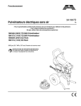
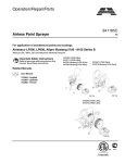
Repair
3A1176A
Interior Texture Sprayer TS650
ENG
For use with water based materials only. For professional use only.
Not approved to European explosive atmosphere requirements.
24F565
50 psi (.35 MPa, 3.5 bar) Maximum Fluid Working Pressure
100 psi (.7 MPa, 7 bar) Maximum Air Input Pressure
Important Safety Instructions
Read all warnings and instructions in this
manual. Save these instructions.
Related Manuals
311969
3A1174
ti8370a
Warnings
Warnings
The following warnings are for the setup, use, grounding, maintenance, and repair of this equipment. The exclamation point symbol alerts you to a general warning and the hazard symbols refer to procedure-specific risks. When
these symbols appear in the body of this manual, refer back to these Warnings. Product-specific hazard symbols and
warnings not covered in this section may appear throughout the body of this manual where applicable.
WARNING
WARNING
GROUNDING
This product must be grounded. In the event of an electrical short circuit, grounding reduces the risk of
electric shock by providing an escape wire for the electric current. This product is equipped with a cord
having a grounding wire with an appropriate grounding plug. The plug must be plugged into an outlet that
is properly installed and grounded in accordance with all local codes and ordinances.
• Improper installation of the grounding plug is able to result in a risk of electric shock.
• When repair or replacement of the cord or plug is required, do not connect the grounding wire to either
flat blade terminal.
• The wire with insulation having an outer surface that is green with or without yellow stripes is the
grounding wire.
• Check with a qualified electrician or serviceman when the grounding instructions are not completely
understood, or when in doubt as to whether the product is properly grounded.
• Do not modify the plug provided; if it does not fit the outlet, have the proper outlet installed by a
qualified electrician.
• This product is for use on a nominal 120V circuit and has a grounding plug similar to the plug
illustrated in the figure below.
• Only connect the product to an outlet having the same configuration as the plug.
•
Do not use an adapter with this product.
Extension Cords:
• Use only a 3-wire extension cord that has a 3-blade grounding plug and a 3-slot receptacle that
accepts the plug on the product.
• Make sure your extension cord is not damaged. If an extension cord is necessary, use 12 AWG
(2.5 mm2) minimum to carry the current that the product draws.
• An undersized cord results in a drop in line voltage and loss of power and overheating.
2
3A1176A
Warnings
WARNING
WARNING
FIRE AND EXPLOSION HAZARD
Flammable fumes, such as solvent, in work area can ignite or explode. To help prevent fire and explosion:
• Use equipment in well ventilated area.
• Sprayer generates sparks. When flammable liquids are used near the sprayer or for flushing or
cleaning, keep sprayer at least 20 feet (6 meters) away from explosive vapors.
• Keep work area free of debris, including solvent, rags and gasoline.
• Ground equipment in the work area. See Grounding instructions.
• If there is static sparking or you feel a shock, stop operation immediately. Do not use equipment until
you identify and correct the problem.
• Keep a working fire extinguisher in the work area.
ELECTRIC SHOCK HAZARD
This equipment must be grounded. Improper grounding, setup, or usage of the system can cause electric
shock.
• Turn off and disconnect power cord before servicing equipment.
• Use only grounded electrical outlets.
• Use only 3-wire extension cords.
• Ensure ground prongs are intact on power and extension cords.
• Do not expose to rain. Store indoors.
PRESSURIZED EQUIPMENT HAZARD
Fluid from the gun/dispense valve, leaks, or ruptured components can splash in the eyes or on skin and
cause serious injury.
• Follow the Pressure Relief Procedure, page 7 when you stop spraying and before cleaning,
checking, or servicing equipment.
• Tighten all fluid connections before operating the equipment.
• Check hoses, tubes, and couplings daily. Replace worn or damaged parts immediately.
3A1176A
3
Warnings
WARNING
WARNING
EQUIPMENT MISUSE HAZARD
Misuse can cause death or serious injury.
• Always wear appropriate gloves, eye protection, and a respirator or mask when painting.
• Do not operate or spray near children. Keep children away from equipment at all times.
• Do not overreach or stand on an unstable support. Keep effective footing and balance at all times.
• Stay alert and watch what you are doing.
• Do not leave the unit energized or under pressure while unattended. When the unit is not in use, turn
off the unit and follow the Pressure Relief Procedure for turning off the unit.
• Do not operate the unit when fatigued or under the influence of drugs or alcohol.
• Do not kink or over-bend the hose.
• Do not expose the hose to temperatures or to pressures in excess of those specified by Airlessco.
• Do not use the hose as a strength member to pull or lift the equipment.
PLASTIC PARTS CLEANING SOLVENT HAZARD
Many solvents can degrade plastic parts and cause them to fail, which could cause serious injury or
property damage.
• Use only compatible water-based solvents to clean plastic structural or pressure-containing parts.
• See Technical Data in this and all other equipment instruction manuals. Read fluid and solvent
manufacturer’s MSDSs and recommendations.
PERSONAL PROTECTIVE EQUIPMENT
You must wear appropriate protective equipment when operating, servicing, or when in the operating area
of the equipment to help protect you from serious injury, including eye injury, hearing loss, inhalation of
toxic fumes, and burns. This equipment includes but is not limited to:
• Protective eyewear, and hearing protection.
• Respirators, protective clothing, and gloves as recommended by the fluid and solvent manufacturer.
4
3A1176A
Warnings
NOTICE
Water or material remaining in unit when temperatures are below freezing can damage
motor and/or delay pump startup.
To insure water and material are completely drained out of unit:
1. Remove material line from sprayer.
2. Tip sprayer up as shown.
ti9075a
J
Before adding material or starting unit in cold weather, run warm water through pump.
Before adding material to hopper, install burp guard (J). When only a small amount of
material remains in the hopper, the burp guard prevents material from shooting out when
the unit is turned off. This material could splash in the operator’s eyes or on skin, or into
the air.
ti8376a
3A1176A
5
Component Identification
Component Identification
P
A
B
N
M
C
H
D
R
ti8369a
E
L
F
G
K
J
Q
3.5 cfm@40 min.
Item
6
Component
Item
Component
A
Pump Hose Outlet
J
Burp Guard
B
RotoFlex™ II Pump (inside)
K
ON/OFF Switch
C
Texture Spray Gun (Manual 311969)
L
Power Cord (120V, 15 ft)
D
Nozzle (2 included)
M
Material Hopper - 5 gallon
E
Material Hose (20 ft)
N
Cord Wrap
F
Material Thickness Gauge
P
Handle
G
Accessories Bag
Q
Air Compressor (Not Supplied)
H
Gun Air Valve
R
Knob/Pressure Control
3A1176A
Component Identification
Pressure Relief Procedure
To reduce risk of injury, follow this procedure whenever
you see this symbol throughout this manual, Also, perform this procedure whenever you:
• Stop spraying
• Check or repair any part of this system
Grounding and Electrical
Requirements
This sprayer must be grounded. Grounding reduces the
risk of electrical shock by providing an escape wire for
the electrical current. The sprayer cord includes a
grounding wire with an appropriate grounding plug. The
plug must be plugged into an outlet that is properly
installed and grounded in accordance with all local
codes and ordinances.
• Install or clean spray nozzle
Check with a qualified electrician or if grounding
instructions are not completely understood, or if in doubt
as to whether the product is properly grounded. Do not
modify plug provided; if it will not fit the outlet, have
proper outlet installed by a qualified electrician.
1. Turn Power Switch OFF.
120V AC Systems
•
This equipment requires a 120V AC, 60 Hz, 15A
circuit with a grounding receptacle. Do not use an
adapter with this product.
ti9165a
Extension Cords
2. Trigger gun into material hopper.
ti8371a
3. Disconnect air gun.
•
Use only an extension cord with an undamaged,
3-prong plug.
•
For 25 to 50 ft (7.6 to 15.2 m) cords, use 3-wire, 14
AWG (1.5 mm2) minimum.
•
For up to 100 ft. (30.48 m) cord, use 3-wire, 12 AWG
(2.5 mm2) minimum.
Auxiliary Air Compressor (Required)
Minimum requirements 3.5 cfm @ 40 psi or 2.5 cfm @
90 psi (see manual 3A1174 for detailed
recommendations).
Generator Requirements (Alternate)
3500 W (3.5 KW) minimum.
ti8568a
Hose Size and Length
The system comes with a hose set consisting of a 3/4 in.
ID x 20 ft (25 mm x 7.6 m) material hose.
3A1176A
7
Shroud Removal
Shroud Removal
Disassembly
Reassembly
1. Relieve Pressure, page 7.
1. Slide shroud (7) onto base (2).
2. Unplug sprayer from outlet.
2. Tighten two bottom screws (15) and two top screws
(64 ) into shroud (7).
ti2810b
3. Remove two screws (15) and two screws (64) from
back of shroud (7).
64
7
15
ti9658a
4. Pull shroud (7) back and up over knob (41).
7
2
ti9659a
8
3A1176A
RotoFlex™ II Pump
RotoFlex™ II Pump
Disassembly
6. Use 3/8 in. socket to remove screw (36) from hose
bracket (27).
1. Relieve Pressure, page 7.
36
2. Unplug sprayer from outlet.
ti9065a
7. Slide hose fittings out of hose bracket (27) and
remove hose (23) from base (2).
ti2810b
3. Remove Shroud, page 8.
4. Loosen two spacers (56) and knob (41).
ti3084a
41
56
ti9657a
5. Loosen hopper fitting by hand to remove hopper (1).
1
ti8781a
3A1176A
9
RotoFlex™ II Pump
Reassembly
1. Bend hose (23) so colored dots on hose fittings face
each other and slide hose fittings through hose
bracket (27).
5. To set pressure, apply petroleum jelly to threads
(41), tighten knob (41) until back of bracket (25) is
approximately 1/2 in. from front of tensioning
bracket (16).
25
16
ti9710a
ti3084a
NOTE: Make sure protective fabric faces outside of
hose. Roller will touch exposed area of pump hose
when pump is in place.
2. Squeeze hose ends together to keep hose (23) and
bracket (27) together and feed pump hose fittings
through holes on front of base.
Tighten front spacer (56) until flush to front of tensioning bracket (16). Tighten back spacer (56) 3/8
in. from tensioning bracket.
25
16
27
23
ti9656a
41
ti8780a
3. Use 3/8 in. socket to tighten screw (36) on hose
bracket (27).
NOTE: To break in new pump, run sprayer dry for no
longer than two minutes.
NOTE: Replace hose when mud seeps through slots in
the base and leaves material on the floor.
4. Install hopper and tighten hopper fitting on hopper
(1) by hand until snug.
ti8787a
10
3A1176A
Motor
Motor
Disassembly
9. Remove two clevis pins (20) from base.
1. Relieve Pressure, page 7.
2. Unplug sprayer from outlet.
20
ti8783a
ti2810b
10. Slide motor tray (32) out of slots in base (2) to
remove motor and tray from sprayer.
3. Remove Shroud, page 8.
2
4. Loosen knob (41) until spring relaxes.
32
41
ti9070a
ti9657a
11. Remove Belt, page 14.
5. Remove Pump, page 9.
12. Loosen bolts (4) and remove motor (31) from motor
tray (32).
6. Disconnect all electrical Wiring, page 17.
32
7. Use 1/4 in. socket to remove grounding screw (22).
31
22
4
ti9064a
ti9214a
8. Disconnect extension cable (29) from pulley (17)
and spring (19) to allow motor tray to pivot.
19
17
29
ti9058a
3A1176A
11
Motor
Reassembly
1. Tighten Belt, page 14.
2. Use petroleum jelly to grease area of shaft that
makes contact with extension cable (29).
6. Pull back on motor tray (32) to create slack in
extension cable (29). Loop extension cable (29)
through pulley (17) and connect to extension spring
(19). Apply petroleum jelly to pulley (17) and threads
on knob (41).
19
17
29
29
ti9060a
ti9059a
3. Slide pin on motor tray (32) into slots on base and
push motor and tray back into position.
7. Tighten knob (41).
32
41
ti9656a
ti9708a
4. Replace two clevis pins (20) in base (2).
8. To set pressure, tighten knob (41) until back of
bracket (25) is approximately 1/2 in. from front of
tensioning bracket.
Tighten front spacer (56) until flush to front of tensioning bracket (16). Tighten back spacer (56) 3/8
in. from tensioning bracket (16).
20
25
56
ti8783a
16
5. Reconnect all electrical wiring including ground wire
(22), Wiring, page 17.
ti9656a
41
22
9. Reassemble Shroud, page 8.
ti9064a
12
3A1176A
Motor Fuse Removal
Motor Fuse Removal
When replacing fuse, use only Bussman GMF-3 (3A) to
prevent premature trips or equipment damage.
The cover will pop up to allow the fuse (F) to be
inspected and replaced if needed.
The motor has a replaceable fuse attached to the motor
bracket. The fuse assembly (A) is fastened to the motor
bracket along with a clamp.
F
A
ti9201a
ti9206a
To remove the motor fuse, press down on the round
center cover (C) and turn it counterclockwise.
C
ti9200a
3A1176A
13
Belt
Belt
Disassembly
Reassembly
1. Relieve Pressure, page 7.
1. Loop one end of belt over extension cable (29) and
pulley (17), then loop other end of belt over motor
shaft (make sure teeth of belt (24) and pulley are
aligned).
2. Unplug sprayer from outlet.
24
ti2810b
ti8784a
3. Remove Shroud, page 8.
4. Remove Motor, page 11.
5. Place motor tray (32) into vice and tighten until
snug.
2. Insert flat screwdriver into slot on back of motor tray
(32) and use screwdriver as a lever to pull motor
(31) into position.
3. Use 9/16 in. wrench to tighten two mounting screws
(4) while keeping motor (31) in position with screwdriver.
32
ti9073a
ti9063a
6. Use 9/16 in. wrench to loosen two mounting screws
(4) on motor tray (32) to allow motor to slide around.
NOTE: Once the motor is in place, you can test the belt
to make sure it is properly tightened. When you push on
the belt (24) with one finger it should move no more than
1/4 in. If it moves more than 1/4 in., go back to step 8
and re-tighten the belt.
24
ti9069a
ti9066a
7. Remove old belt and discard.
ti9071a
4. Reassemble Motor, page 11.
5. Reassemble Shroud, page 8.
14
3A1176A
Troubleshooting
Troubleshooting
Problem
Sprayer won’t run
Pump won’t pump material
Cause
Solution
Power switch not on
Turn switch on.
No power at wall outlet
Check outlet by seeing if light in the
plug is illuminated. If not, try another
outlet.
Wrong size generator
Use a 3500 watt or larger generator.
Refer to Generator Requirements,
page 7.
Too many items on same circuit
Unplug other items from circuit
Extension cord too long or wrong
gauge
Use a different extension cord. Refer
to Grounding and Electric Requirements, page 7.
Breaker tripped
Reset breaker.
Blown motor fuse
Check to see if fuse needs to be
replaced. Refer to Motor Fuse
Removal, page 13.
Failed motor or motor shield
Replace motor or motor fuse.
Mix too thick
Add water to thin material. Use Material Thickness Gauge.
Plugged gun
Relieve Pressure, page 7. Remove
gun from hose. Clean gun.
RotoFlex II pump worn out
Replace hose. Recommended hose
replacement - once a year or every
3000 gallons.
Pump cold or material frozen in pump Move pump to warm room and allow
it to warm up or run hot water through
sprayer.
Material in hose
Remove material hose from outlet
and run until material flows.
Material runs out of bottom of sprayer RotoFlex II pump worn out
onto floor
Replace hose.
No air flowing from gun
Gun air valve closed
Open gun air valve.
Gun needle plugged
Clean needle and retry.
Lines not connected
Check all connections to gun and
hoses.
Damaged hose
Replace hose.
Worn compressor
Replace compressor.
3A1176A
15
Troubleshooting
Problem
Speed of application too slow
Cause
Solution
New pump hose not broken in
properly
Run pump dry for no longer than 2
minutes.
Material too thick
Thin material.
Nozzle too small
Change nozzles to a larger size. See
Operation Manual, Recommended
Nozzle Selection Chart.
Plugged or dirty gun
Relieve Pressure, page 7. Clean
gun.
Kinked hose
Unkink hose.
Gun fluid flow adjustment set too low Increase flow adjustment with flow
adjustment nut.
Intermittent flow/sputtering
Gun will not shut off
Hopper connection not tight
Check gasket. Tighten connection.
Debris in system
Clean system.
Worn nozzle or needle.
Relieve Pressure, page 7. Replace
worn parts.
Debris in needle passage
Relieve Pressure, page 7. Clean.
Fluid leaking at Flow Adjustment Nut Damaged seal.
on gun
Relieve Pressure, page 7. Replace
seal.
Fluid leaking out of either plug on gun Missing or damaged o-rings
Relieve Pressure, page 7. Replace
o-rings.
Needle adjustment on gun won’t
adjust
16
Gun damaged
Replace gun.
Dirty threads
Clean threads.
Nozzle not on gun
Put nozzle on gun.
3A1176A
Wiring Diagram
Wiring Diagram
31
39
10
Motor
ON/OFF
Switch
Red
Wire
Green
Wire
Black Wire
Black Wire
Green Wire
White
Wire
Chassis Ground
25
White
Wire
8
Power Cord
ti9199a
3A1176A
17
Parts
Parts
Models 24F565
9
42
64
7
6
55
•
13
9
12
18
2
42
65
•
•
1
64
15
46
56
25
•
47
41
ti9654a
•
8
37
10
14
5
3
28
39
37
63
31
4
20
2
21 43
24
38
17
11
16
19
22
32
30
29
20
36
33
ti9655a
27
44
26
18
23
3A1176A
Parts
Ref.
1
2
3
4
5
6
7
8
9
10
11
12
13
14
15
16
17
18
19
20
21
22
23
24
25
26
27
28
Part
†
3A1176A
15J187
15J181
15J185
117791
120783
15J186
288685
15J505
120817
117693
120700
15J222
15K512
15J388
120648
15K154
15J459
15H868
120657
15J510
101242
115498
288623
288718
15K155
288622
15J500
15J506
Description
Qty.
1
HOPPER, 5 gallon
1
BASE
1
FRAME, tubular, painted, black
2
SCREW, cap, tri lobe
3
SCREW, mach, pnh
1
HANDLE, tubular, painted, black
1
COVER, adjustable
1
CORD, power
2
FASTENER, push-on hat w/hole
1
SWITCH, power
1
SCREW, shoulder
1
GUARD, burp
1
LABEL, warning
2
DAMPENER, feet
2
SCREW
1
LEVER, spring, tensioning
1
PULLEY
1
LABEL, instruction
1
SPRING, extension
2
PIN, detent clevis
2
RING, retaining, ext.
2
SCREW, mach, slot hex wash hd
1
HOSE, pump (Roto-Flex™)
1
BELT, timing
1
BRACKET, cover/cord
1
HOSE, coupled, 20 feet
1
BRACKET, hose
1
BAG, accessories
Ref.
29
30
31
32
33
36
37
38
39
41
42
43
44
45
46
47
55
56
63
64
65
66
Part
120658
255171
288740
288229
288225
120444
117633
15C090
288739
15K143
114538
120757
102040
103473
16F594
15K339
15E298
120770
120830
120771
100527
181250
Description
CABLE, extension
GUN, spray
MOTOR (includes item 39)
TRAY, motor, weld
PULLEY, w/rollers
SCREW, hex hd, flanged
SCREW, slot hex wash hd
GAUGE, thickness, fluid
FUSE, Bussman GMF-3 (3A)
KNOB
SCREW, mach, torx, pan hd
SCREW, carriage, shoulder
NUT, lock, hex
STRAP, tie, wire
LABEL, front
LABEL, control
LABEL, ident
SHAFT, collar
CLAMP, loop
SCREW
WASHER
LABEL, designation
Qty.
1
1
1
1
1
1
5
1
1
1
2
1
1
2
1
1
2
2
1
3
2
1
▲ Labels are not included with components. They
must be ordered separately.
† Additional warning labels are available at no cost.
19
Technical Data
Technical Data
Main Unit Power Requirements . . . . . . . . . . . . . . . . . . .
120 Vac, 60 Hz, 15A, 1 phase
Maximum Fluid Working Pressure. . . . . . . . . . . . . . . . .
50 psi (.35 MPa, 3.5 bar)
Maximum Air Working Pressure . . . . . . . . . . . . . . . . . .
100 psi (.7MPa, 7 bar)
Compressor Specifications . . . . . . . . . . . . . . . . . . . . . .
Universal motor thermally protected, oil-less
Compressor (Not Supplied) . . . . . . . . . . . . . . . . . . . . . .
3.5 @ 40 psi minimum
Generator (Optional) . . . . . . . . . . . . . . . . . . . . . . . . . . .
3500 W minimum
Electric Motor . . . . . . . . . . . . . . . . . . . . . . . . . . . . . . . .
Permanent Magnet DC-5A
Power Cord . . . . . . . . . . . . . . . . . . . . . . . . . . . . . . . . . .
16 AWG, 3-wire, 15 ft
Material Hopper Capacity . . . . . . . . . . . . . . . . . . . . . . .
5 gallons
Maximum Delivery with Texture . . . . . . . . . . . . . . . . . . .
0.65 gpm
TS650 Dimensions and Weight
Length . . . . . . . . . . . . . . . . . . . . . . . . . . . . . . . . . . .
19 in. (482 mm) with handle
Width. . . . . . . . . . . . . . . . . . . . . . . . . . . . . . . . . . . .
12 in. (305 mm)
Height (no handle) . . . . . . . . . . . . . . . . . . . . . . . . .
20 in. (508 mm)
Weight (includes hoses or gun). . . . . . . . . . . . . . . .
33 lb (14.9 kg)
Wetted Parts . . . . . . . . . . . . . . . . . . . . . . . . . . . . . . . . .
brass, aluminum, plastic
Sound Data (less compressor)
Sound Pressure Level. . . . . . . . . . . . . . . . . . . . . . .
N/A
Sound Power Level . . . . . . . . . . . . . . . . . . . . . . . . .
N/A
Storage Temperature Range . . . . . . . . . . . . . . . . . . . . .
35°F - 160°F (1.6°C - 71°C)
Operating Temperature Range . . . . . . . . . . . . . . . . . . .
40°F - 115°F (4°C - 46°C)
Gun:
20
Maximum Fluid Working Pressure . . . . . . . . . . . . .
70 psi (.5 MPa, 5 bar)
Maximum Air Working Pressure . . . . . . . . . . . . . . .
125 psi (.86 MPa, 8.6 bar)
CFM Rating. . . . . . . . . . . . . . . . . . . . . . . . . . . . . . .
3.0 - 11 CFM
Weight . . . . . . . . . . . . . . . . . . . . . . . . . . . . . . . . . . .
1.1 lb (500 g)
3A1176A
Notes
Notes
3A1176A
21
Airlessco Standard Warranty
Airlessco warrants all equipment referenced in this document which is manufactured by Airlessco and bearing its name to be free from defects in
material and workmanship on the date of sale to the original purchaser for use. With the exception of any special, extended, or limited warranty
published by Airlessco, Airlessco will, for a period of twelve months from the date of sale, repair or replace any part of the equipment determined
by Airlessco to be defective. This warranty applies only when the equipment is installed, operated and maintained in accordance with Airlessco’s
written recommendations.
This warranty does not cover, and Airlessco shall not be liable for general wear and tear, or any malfunction, damage or wear caused by faulty
installation, misapplication, abrasion, corrosion, inadequate or improper maintenance, negligence, accident, tampering, or substitution of
non-Airlessco component parts. Nor shall Airlessco be liable for malfunction, damage or wear caused by the incompatibility of Airlessco equipment
with structures, accessories, equipment or materials not supplied by Airlessco, or the improper design, manufacture, installation, operation or
maintenance of structures, accessories, equipment or materials not supplied by Airlessco.
This warranty is conditioned upon the prepaid return of the equipment claimed to be defective to an authorized Airlessco distributor for verification
of the claimed defect. If the claimed defect is verified, Airlessco will repair or replace free of charge any defective parts. The equipment will be
returned to the original purchaser transportation prepaid. If inspection of the equipment does not disclose any defect in material or workmanship,
repairs will be made at a reasonable charge, which charges may include the costs of parts, labor, and transportation.
THIS WARRANTY IS EXCLUSIVE, AND IS IN LIEU OF ANY OTHER WARRANTIES, EXPRESS OR IMPLIED, INCLUDING BUT NOT LIMITED
TO WARRANTY OF MERCHANTABILITY OR WARRANTY OF FITNESS FOR A PARTICULAR PURPOSE.
Airlessco’s sole obligation and buyer’s sole remedy for any breach of warranty shall be as set forth above. The buyer agrees that no other remedy
(including, but not limited to, incidental or consequential damages for lost profits, lost sales, injury to person or property, or any other incidental or
consequential loss) shall be available. Any action for breach of warranty must be brought within two (2) years of the date of sale.
AIRLESSCO MAKES NO WARRANTY, AND DISCLAIMS ALL IMPLIED WARRANTIES OF MERCHANTABILITY AND FITNESS FOR A
PARTICULAR PURPOSE, IN CONNECTION WITH ACCESSORIES, EQUIPMENT, MATERIALS OR COMPONENTS SOLD BUT NOT
MANUFACTURED BY Airlessco. These items sold, but not manufactured by Airlessco (such as electric motors, switches, hose, etc.), are subject
to the warranty, if any, of their manufacturer. Airlessco will provide purchaser with reasonable assistance in making any claim for breach of these
warranties.
In no event will Airlessco be liable for indirect, incidental, special or consequential damages resulting from Airlessco supplying equipment
hereunder, or the furnishing, performance, or use of any products or other goods sold hereto, whether due to a breach of contract, breach of
warranty, the negligence of Airlessco, or otherwise.
FOR AIRLESSCO CANADA CUSTOMERS
The Parties acknowledge that they have required that the present document, as well as all documents, notices and legal proceedings entered into,
given or instituted pursuant hereto or relating directly or indirectly hereto, be drawn up in English. Les parties reconnaissent avoir convenu que la
rédaction du présente document sera en Anglais, ainsi que tous documents, avis et procédures judiciaires exécutés, donnés ou intentés, à la suite
de ou en rapport, directement ou indirectement, avec les procédures concernées.
TO PLACE AN ORDER OR FOR SERVICE, contact your Airlessco distributor,
or call 1–800–223-8213 to identify the nearest distributor.
All written and visual data contained in this document reflects the latest product information available at the time of publication.
Airlessco reserves the right to make changes at any time without notice.
Original Instructions. This manual contains English. MM 3A1176
Airlessco, 3501 N. 4th Avenue, Sioux Falls, SD 57104
Copyright 2010, Graco Inc. is registered to ISO 9001
www.airlessco.com
08/2010