1
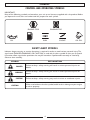
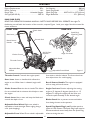
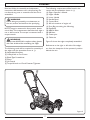
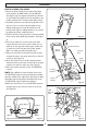
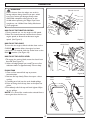
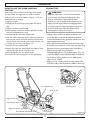
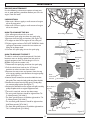
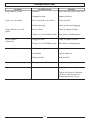
USER MANUAL 4 Stroke Petrol Edger SAFETY OPERATION MAINTENANCE Your edger has been engineered and manufactured to our high standard for dependability, ease of operation, and operator safety. WARNING: To reduce the risk of injury, the user must read and understand the operator’s manual before using this product. Thank you for your purchase. SAVE THIS MANUAL FOR FUTURE REFERENCE Model No. ME240 WARRANTY INFORMATION PETROL EDGER WARRANTY The benefits conferred by this warranty are in addition to all other conditions and warranties in respect of this product which the consumer may have taken under the Trade Practices Act 1974 or by any legislation of a State or Territory of Australia. This product is warranted by Husqvarna Australia (ABN 45 115 475 619) (the “Company”) to be free from defects in material and workmanship for a period of 24 months from the date of original purchase. The Company during the period of the warranty, will at its option, and subject to the conditions stated herein, repair or replace without charge this product or any component part, which upon examination by an Authorised Service Agent or by the Company is found to be defective. Warranty conditions This warranty will not apply: (i) where this product has been subjected to misuse, abuse, accident or want of care; (ii) where this product has been used for a purpose for which it was not designed or is not suited; (iii) where the service of this product has been undertaken by a person not authorised by the Company to carry out such work or where parts that have not been approved by the Company have been used; (iv) where this product has been used for industrial purposes. Should service become necessary during the warranty period, the purchaser should contact an Authorised Service Agent or the Company. In order to obtain warranty service, the purchaser must present the store receipt showing the name of the retailer and the date of purchase together with a completed Warranty Card. The period of the warranty begins from the original date of purchase, notwithstanding any subsequent repair or parts replacement. No additional warranty or guarantee other than set out in this document, whether written or verbal, is authorised to be made on the Company’s behalf. The purchaser shall be responsible for delivery or causing the product to be delivered to the Company or the Authorised Service Agent and the purchaser shall be responsible for all charges in connection with re-delivery of the product and/or the delivery of parts. Damage in transit is not covered by this warranty and purchasers should remove from the product any liquids (if applicable) before sending and pack the product securely to prevent damage. WARRANTY EXCLUSIONS Normal wear parts or components are subject to seperate terms as follows: Normal wear parts, components or service required when performing normal and regular maintenance of this product are not covered by warranty unless it is found to be defective by an Authorised Service Agent or by the Company. Normal wear parts include, but are not limited to: Worn Blades. Carburettor Tune-Ups. Belt. Lubricants. Spark Plugs. Engine Tune-Ups. Filters. Returns based on the above listed normal wear parts will not be accepted under this warranty as they are considered consumable items and are at the expense of the purchaser. TABLE OF CONTENTS n General Safety Rules. . . . . . . . . . . . . . . . . . . . . . . . . . . . . . . . . . . . . . . . . . . . . . . . . . . . . . 1-2 n Specific Safety Rules. . . . . . . . . . . . . . . . . . . . . . . . . . . . . . . . . . . . . . . . . . . . . . . . . . . . . . . . 3 n Symbols. . . . . . . . . . . . . . . . . . . . . . . . . . . . . . . . . . . . . . . . . . . . . . . . . . . . . . . . . . . . . . . . 4-5 n Features . . . . . . . . . . . . . . . . . . . . . . . . . . . . . . . . . . . . . . . . . . . . . . . . . . . . . . . . . . . . . . . . . 6 n Assembly. . . . . . . . . . . . . . . . . . . . . . . . . . . . . . . . . . . . . . . . . . . . . . . . . . . . . . . . . . . . . . . 7-8 n Operation. . . . . . . . . . . . . . . . . . . . . . . . . . . . . . . . . . . . . . . . . . . . . . . . . . . . . . . . . . . . . 9-13 n Maintenance. . . . . . . . . . . . . . . . . . . . . . . . . . . . . . . . . . . . . . . . . . . . . . . . . . . . . . . . . . 14-16 n Troubleshooting . . . . . . . . . . . . . . . . . . . . . . . . . . . . . . . . . . . . . . . . . . . . . . . . . . . . . . . . . . 17 INTRODUCTION This tool has many features for making its use more pleasant and enjoyable. Safety, performance, and dependability have been given top priority in the design of this product making it easy to maintain and operate. GENERAL SAFETY RULES This manual is written for a person with some mechanical ability. Like most service books, not all the steps are described. Steps on how to loosen or tighten fasteners are steps anyone can follow with some mechanical ability. Read and follow these instructions before you use the unit. WARNING Look for this symbol to point out important safety precautions. It means: “ Attention! Become Alert! Your Safety Is Involved.” WARNING Engine Exhaust, some of its constituents, and certain vehicle components contain or emit chemicals known to cause cancer and birth defects or other reproductive harm. Know your product: If you understand the unit and how the unit operates, you will get the best performance. As you read this manual, compare the illustrations to the unit. Learn the location and the functions of the controls. To help prevent an accident, follow the operating instructions and the safety rules. Keep this manual for future reference. WARNING To prevent accidental starting when setting up, transporting, adjusting or making repairs, always disconnect spark plug wire and put wire where it cannot contact the spark plug. IMPORTANT: Many units are not assembled and are sold in cartons. It is the responsibility of the operator to make sure the assembly instructions in this manual are exactly followed. Other units are purchased in an assembled condition. On assembled units, it is the responsibility of the operator to make sure the unit is correctly assembled. The operator must carefully check the unit according to the instructions in this manual before it is first used. with the controls and the proper use of the edger before starting. Know how to stop the edger and disengage the controls quickly. • Familiarise yourself with all the safety and operating decals on this equipment. • Thoroughly inspect the area where the edger is to be used and remove all foreign objects.Your equipment can propel small objects at high speed causing personal injury or property damage. Stay away from breakable objects, such as house windows, auto glass, greenhouses, etc. • Check that all nuts and bolts are tight and equipment is in good condition. RESPONSIBILITY OF THE OPERATOR The responsibility of the operator is to follow the instructions below: 1. Carefully read and follow the rules for safe operation. 2. Follow all the assembly and preparation instructions. 3. Regularly inspect the edger. Make sure parts are not bent, damaged, or loose. 4. Use this equipment for its intended purpose only. 5. Make sure that the operator of the unit knows how to correctly use all standard and accessory equipment. 6. Operate the unit only with guards, shields, and other safety items in place and working correctly. 7. Correctly adjust the unit. 8. Service the unit only with authorised or approved replacement parts. 9. Complete all maintenance on the unit. SAFE OPERATION PRACTICES BEFORE USE • Read, understand, and follow all instructions on the machine and in the manuals. Be thoroughly familiar OPERATION SAFETY • Never allow children or young teenagers to operate the edger. • Keep area of operation clear of all bystanders, particularly small children and pets. • Only allow responsible individuals, who are familiar with the instructions, to operate the edger. • Do not operate the edger while under the influence of alcohol, drugs, or other medication which can cause drowsiness or affect your ability to operate this machine safely. • Do not use this machine if you are mentally or physically unable to operate the machine safely. • Always wear ANSI/SAA compliant safety goggles GENERAL SAFETY RULES or safety glasses with side shields when operating edger to protect your eyes from foreign objects, which can be thrown from the unit. • Wear appropriate clothing such as a long sleeved shirt or jacket. Also wear long trousers or slacks. Do NOT wear shorts. Do NOT wear loose clothing, which could get caught in this equipment. • Always wear work gloves and sturdy footwear such as leather work shoes or short boots. These will protect ankles and shins from small sticks, splinters, and other flying debris, and improve traction. • It is advisable to wear protective headgear to protect against being struck by small flying particles, or being struck by low hanging branches, twigs, or other objects, which may be unnoticed by the operator. • Do not put hands or feet near or under rotating parts. • Exercise extreme caution when operating on or crossing gravel drives, walks, or roads. Stay alert for hidden hazards or traffic. • Exercise caution to avoid slipping or falling. Always besure of your footing; keep a firm hold on the handle and walk; never run. Never operate the edger at high transport speeds on slippery surfaces. • Look behind and use care when backing. • Never operate the edger without good visibility or light. • Do not run the engine indoors or inside a closed area. The exhaust fumes are dangerous, containing CARBON MONOXIDE, an ODORLESS AND DEADLY GAS. • Never leave the edger unattended when the engine is running. Stop the engine and make sure all moving parts have stopped. Remove the wire from the spark plug. • Do not overload the edger capacity by attempting to till too deep at too fast a rate. • If the edger should start to vibrate abnormally, stop the engine, disconnect the spark plug wire and prevent it from touching the spark plug. Check immediately for the cause.Vibration is generally a warning of trouble. • Watch for holes, ruts, bumps, or other rough ground. Tall grass can hide obstacles. SPECIFIC SAFETY RULES FUEL SAFETY • Handle fuel with care; it is highly flammable. • Use an approved container. • Check fuel supply before each use, allowing space for expansion as the heat of the engine and/or sun can cause fuel to expand. • Fill fuel tank outdoors with extreme care. Never fill fuel tank indoors. • Never remove petrol cap or add fuel with the engine running. Allow engine to cool before refueling. • Do not smoke while refueling. • After refueling, replace fuel tank cap securely and wipe up spilled fuel. • Never store fuel or edger with fuel in the tank inside a building where fumes may reach an open flame. • When servicing or repairing the edger, do not tip the machine over or up unless specifically instructed to do so in this Manual. Service and repair procedures can be done with the edger in an upright position. Some procedures will be easier if the machine is lifted on a raised platform or working surface. • Use only original equipment or authorised replacement parts. • Never tamper with safety devices. Check their proper operation regularly. • Do not change the engine governor setting or over-speed engine. • Clean and replace safety and instruction decals as necessary. • To guard against engine over-heating, always have engine air filter mounted and clean. STORAGE SAFETY • Always refer to the operator’s manual instructions for important details if the edger is to be stored for an extended period. • Never store the edger with fuel in the fuel tank inside a building where ignition sources are present such as water heaters, space heaters, clothes dryers, etc. • To reduce fire hazard, keep edger free of grass, leaves, or other debris build-up. • Allow the engine to cool before storing in any enclosure. CHILDREN SAFETY • Tragic accidents can occur if the operator is not alert to the presence of children. Children are often attracted to the edger and the edging activity. • Keep children out of the edging area and under the watchful care of a responsible adult. • Never assume that children will remain where you last saw them. • Be alert and turn edger off if children enter the area. • Before and while moving backwards, look behind and down for small children. • Never allow children to operate the edger. • Use extra care when operating near blind corners, shrubs, trees, or other objects that may obstruct vision. REPAIR, MAINTAINANCE, AND ADJUSTMENT SAFETY • After striking a foreign object, stop the engine. Remove the spark plug lead from the spark plug and keep the spark plug lead away from the plug to prevent accidental starting. Thoroughly inspect the edger for any damage. If damaged, have the equipment repaired by a trained technician before restarting and operating. • Stop the engine before cleaning, repairing, or inspecting the unit. Make sure all moving parts have stopped. Let the engine cool, disconnect the spark plug lead and move it away from the spark plug. • Never attempt to make any adjustments while the engine is running except when specifically recommended by the manufacturer. • Keep the edger in safe working condition. Check all fasteners at frequent intervals for proper tightness. SYMBOLS CONTROL AND OPERATING SYMBOLS IMPORTANT: Many of the following symbols are located on your unit or on literature supplied with the product. Before you operate the unit, learn and understand the purpose for each symbol. ENGINE STOP OIL FUEL ENGINE STOP RUN CHOKE OIL FILL SAFETY ALERT SYMBOLS Indicates danger, warning, or caution. Attention is required in order to avoid serious personal injury. The signal word (DANGER, WARNING, OR CAUTION) is used with the alert symbol to alert you to special instruction about a particular operation that may be hazardous if performed incorrectly or carelessly. Observe them carefully. SYMBOL EXPLANATION DANGER Failure to obey a safety warning will result in serious personal injuries or deaths. WARNING Failure to obey a safety warning can result in serious personal injuries or deaths. CAUTION Failure to obey a safety warning may result in minor or moderate injuries. CAUTION When used without the alert symbol, could result in damage to your engine or other property. SYMBOLS SAFETY WARNING SYMBOLS SYMBOL DEFINITION Indicates WARNING, DANGER, or CAUTION. Read operator’s manual before operating this machine. Failure to follow directions could result in serious injury. Thrown objects. Do not use if children or bystanders are present. Remove all objects which could be thrown by machine. Read operator’s manual before operating this machine. Rotating parts can cause serious injury. Keep away from rotating parts. Stop engine and disconnect spark plug wire before making adjustments. Wear eye protection complying with SAA ANSI Z87.1 and hearing protection. Disconnect spark plug wire before servicing unit. Engine emits carbon monoxide. Do NOT run indoors or in enclosed area. Do NOT touch hot muffler or cylinder. These parts are extremely hot from operation and may remain hot for a short time after operation. To reduce risk of fire, clean spilled gas and oil and keep unit free from debris. Petrol is extremely flammmable. Allow machine to cool before refueling. FEATURES Engine Displacement . . . . . . . . . . . . . . . . . . . . . . 87cc Petrol Capacity . . . . . . . . . . . . . . . . . . . . . . . . . .1.6 L Petrol Type . . . . . . . . . . . . . . . . . . Unleaded Regular Oil Type (API SG-SL) . . . . . . . . . . . . . . . . . . . . SAE 30 Oil Capacity . . . . . . . . . . . . . . . . . . . . . . . . . [400 ml] Spark Plug Model . . . . . . . . . . . . . . . . . . . . . . E7RTC Spark Plug Gap . . . . . . . 0.027-0.031 in. [0.7-0.8 mm] Edger Blade Size . . . . . . . . . . . . . . . . . 9 in. [228 mm] KNOW YOUR EDGER READ THE OPERATOR’S MANUAL AND ALL SAFETY RULES BEFORE YOU OPERATE the edger. To familiarise yourself with the location of the controls, compare Figure 1 with your edger. Save this manual for future reference. FRONT VIEW REAR VIEW Clutch Lever Spark Plug/ Spark Plug Lead Start Lever Recoil Starter Handle Control Rod Choke Control Oil Fill Cap/ Dipstick Angle Cut Lever Blade Guard Throttle Control Adjustable Rear Wheel Adjustable Front Wheel Figure 1 from side to side for balance. The front wheel can also adjust down for curb-hopping. Throttle Control Controls the engine speed. Start Lever Lever on handle which allows the engine to run. When lever is released, engine will stop. Recoil Starter Handle The engine is equipped with an easy pull recoil starter. Angle Cut Lever Permits adjusting the cutting angle to 15 degrees, 0 degrees (vertical), or -15 degrees. To change the angle, pull the lever and rotate the quill assembly to the desired angle. Choke Control Restricts the air intake. This allows for an enriched fuel-air mixture which helps to start the engine. Clutch Lever Use to start and stop the blade and control the depth of cut. Blade Guard Use to prevent stones and debris from being thrown at the operator. Adjustable Rear Wheel Right rear wheel is adjustable to level the edger when edging along a curb (curb-hopping). Spark Plug/Spark Plug Lead Provides spark to ignite air/ fuel mixture. The Spark Plug Lead must be disconnected and moved away from the Spark Plug when servicing the unit. Adjustable Front Wheel Front wheel is adjustable 6 ASSEMBLY Read and follow the assembly and adjustment instructions. All fasteners are in the parts bag. Do not discard any parts or materials until the unit is assembled. The following components will be found in the carton with the quantities shown in ( ): (1) Edger Operator’s Manual (1) Upper Handle (1) Lower Handle (1) Handle Panel (1) Control Rod (1) 400 ml container of engine oil (1) Parts Bag containing the following: (4) Pipe Bolts (4) M8X16 Bolts (8) M8 Nuts (2) Cotter pins (2) Cable ties WARNING Before doing any assembly or maintenance to the unit, remove the lead from the spark plug. NOTE: Torque is measured in foot-pounds (metric unit is Nm). This measurement describes how tight a nut or bolt must be. The torque is measured with a torque wrench. WARNING Always wear ANSI/SAA compliant safety glasses with side shields while assembling the edger. Figure 2 shows the edger completely assembled. References to the right or left side of the edger are from the viewpoint of the operator’s position behind the unit. The following tools will be required for assembly of the edger with the quantities shown in ( ): (2) Adjustable Wrenches (1) Utility Knife to Cut Carton (1) Blade Type Screwdriver (1) Pliers (1) Oil Funnel (1) Torque Wrench to Check Fastener Tightness Figure 2 7 ASSEMBLY HOW TO ASSEMBLE THE HANDLE 1. Mount the lower handle to the inside of the edger frame with the (4) M8X16 bolts, and (4) M8 Nuts (See Figure 3). As you tighten the fasteners, pull back on the handle. The torque for all nuts and bolts in the handle should be 7.4-11.8 foot-pounds [10-16 Nm]. 2. Assemble panel with nuts and bolts provided. Insure that the nuts are to the inside. Assemble the top folding handle with the 2 handle lock levers and bolts provide. Tighten folding Handles in to position by tightening locking handles by hand. 3. Connect the wires using the plastic connectors fitted. Secure wires with handle clips provided. (See Figure 4) 4. Use the (2) cable ties to secure the loose cable coming from the start lever to the handle. Use (1) cable tie on the right side of the upper handle and (1) cable tie on the left side of the lower handle. Make sure cable goes behind handle panel. 5. Slide one end of the control rod from left to right through the hole in the clutch lever. Secure with the cotter pin. (See Figure 5) 6. Move the clutch lever to the first depth position. Attach the other end of the control rod to the quill support arm with the cotter pin. (See Figure 5) 7. Move the clutch lever back to the “N” NEUTRAL position. NOTE: If it is difficult to move the clutch lever to the “N” NEUTRAL position, loosen the fasteners that hold the lower handle to the edger frame (See Figure 5). Raise the handle until the clutch lever will easily move to the “N” NEUTRAL position.Tighten the fasteners. 8. When the clutch lever is in the NEUTRAL position, the quill support arm must be close to the screw. (See Figure 6) Edger Engine M8x16 Figure 4 Cotter Pin Neutral Position Upper Handle M8 Nut Locking Handles Control Rod Locking Handles Quill Support Arm Cotter Pin Lower Handle Figure 5 Quill Support Arm M8x16 Screw M8 Nuts M8x16 Edger Frame M8x16 Figure 6 Figure 3 8 OPERATION ENGINE PREPARATION ENGINE DOES NOT CONTAIN OIL OR Petrol WHEN SHIPPED Before you use the unit, read the information on safety, operation, maintenance, and storage. This edger was shipped with a 400 ml contain er of SAE30 motor oil. This oil is to be added to the engine before operating. Follow the below procedure to fill the crankcase with oil. IMPORTANT: This unit is equipped with an internal combustion engine and must not be used on or near any forest-covered, brush-covered or grass-covered land unless the engine’s exhaust system is equipped with a spark arrestor meeting applicable local or state laws. If a spark arrestor is used, the operator must maintain it in effective working order. CHECKLIST For the best performance and satisfaction from this quality product, please review the following checklist before you operate the edger: • All assembly instructions have been completed. • Check carton to make sure no parts are remaining. • All fasteners have been properly tightened. FIRST TIME FILL 1. P lace the edger on a level surface and make sure the adjustable wheels are set so the main frame of the edger is level. 2. Remove the oil fill cap/dipstick. Note: the crankcase is shipped empty. Fill with 400 ml of oil. 3. When adding oil, use a funnel or a nozzle for the oil container to reduce spillage. 4. D O NOT OVERFILL. Check the oil level by following the instructions below. As you learn how to use the edger, pay extra attention to the following important items: • Engine oil is at proper level. • F uel tank is filled with a fresh, clean, regular unleaded petrol. •B ecome familiar and understand the function of all controls. Before you start the engine, operate all controls. TO CHECK THE OIL LEVEL AND FILL TO PROPER LEVEL 1. P lace the edger on a level surface and make sure the curb-hoping wheels are set so the main frame of the edger is level. 2. R emove the oil fill cap/dipstick and wipe clean with cloth. (See Figure 7) 3. R eplace dipstick and do NOT screw it. Remove and check oil level. 4. When oil level is full, the oil will be at upper limit on dip stick. (See Figure 8) 5. If the oil level is near or below the lower limit mark on the dipstick (See Figure 8), add oil slowly and recheck until oil level reaches upper limit of dipstick. DO NOT OVERFILL. 6. Replace and tighten dipstick. 7. Clean up any spilled oil. NOTE: When adding oil, frequently insert the oil fill cap/dipstick and check the amount of oil in the engine. DO NOT OVERFILL. Fuel Tank Oil Fill Cap/ Dipstick Figure 7 Oil Fill Cap/ Dipstick WARNING Follow the user manual instructions for the type of petrol and oil to use. Always use a safety petrol container. Do not smoke when adding petrol to the engine. When inside an enclosure, do not fill with petrol. Before you add petrol, stop the engine. Let the engine cool for several minutes. Upper Limit Lower Limit Figure 8 OPERATION WARNING Debris thrown from the edger can result in foreign objects being thrown into eyes, which can cause severe eye damage. Always wear ANSI/SAA compliant safety glasses or eye shields when operating the edger. If you wear eyeglasses, use a Wide Vision Safety Mask over your eyeglasses. Throttle Control Increasing Speed Decreasing Speed HOW TO USE THE THROTTLE CONTROL 1. During normal use, run the engine at full speed. 2. Move the throttle control rearward to increase engine speed, or forward to decrease engine speed. (See Figure 9) IDLE Figure 9 HOW TO USE THE CHOKE To start the the engine, slide the choke lever to the CHOKE position. After the engine has been running for 2-5 seconds, slide the choke lever to the RUN position. (See Figure 10) Choke Lever RUN HOW TO USE THE CLUTCH LEVER 1. To engage the cutting blade, move the clutch lever forward. (See Figure 11) 2. Select the edging depth you need. There are five selections down to approximately 70 mm deep. Choke FILLING TANK 1. Clean surface around fuel cap to prevent contanimation. 2. Remove fuel cap slowly. Place the cap on a clean surface. 3. Carefully pour fuel into the tank. Avoid spillage. 4. Prior to fitting the fuel cap, clean and inspect the gasket. 5. Immediately refit fuel cap and hand tighten. Wipe up any spillage. NOTE: It is normal for smoke to be emitted from a new engine after the first use. Figure 10 Start Lever Clutch Control Forward Neutral Full Depth Figure 11 10 OPERATION HOW TO START THE ENGINE DO NOT allow the starter rope to snap back. Let the starter rope slowly rewind. If the engine does not start in 5 or 6 tries, see the instruction in the “Troubleshooting Chart”. NOTE:THE START LEVER HAS TO BE ALWAYS HELD AGAINST THE HANDLE FOR THE ENGINE TO RUN. 10. After the engine starts, wait 2-5 seconds and slide the choke back to the RUN position. 11. When the engine is running, move the throttle control lever forward (SLOW Position) to decrease speed or backwards (FAST position) to increase speed. During normal use keep the throttle in the FAST position. (See Figure 9) NOTE: DO NOT BE ALARMED; your engine will smoke the first time it is started. It is burning off the protective coating that is on the internal engine parts. NOTE: Make sure engine is level before starting. IMPORTANT: Before you start the engine, move the edger to the desired location. Operate the controls several times. Make sure all controls move freely. 1. Check the oil. 2. Fill the fuel tank with regular unleaded petrol. Make sure the petrol is clean. Leaded petrol will increase deposits and shorten the life of the valves. HOW TO STOP THE EDGER Release the start lever. This will ground the flameout wires and stop the engine. NOTE: Do not use gasohol or methanol. Do not use premium-unleaded petrol. WARNING Never run the engine indoors or in a poorly ventilated area. Engine exhaust contains carbon monoxide, an odorless and deadly gas. Keep hands, feet, hair, and loose clothing away from any moving parts. Avoid the muffler and surrounding areas. Temperatures can exceed 150 degrees. WARNING Always use a safety petrol container. Do not smoke when adding petrol to the fuel tank. When inside an enclosure, do not add petrol. Before you add petrol, stop the engine and let the engine cool for several minutes. 3. Make sure the spark plug lead is connected to the spark plug. 4. Pull the clutch lever all the way back to raise and disengage the blade 5. Move the throttle control lever all the way to full throttle. 6. Slide the choke to the CHOKE position. (See Figure 10) 7. Hold the recoil starter handle firmly with your right hand. 8. Hold the edger handle firmly with your left hand, pulling the start lever against the handle. THE ENGINE WILL NOT START IF THE START LEVER IS NOT PULLED AGAINST THE HANDLE (FIGURE 11). 9. Pull the recoil slowly, until you feel tension in the starter rope. Then quickly pull the recoil starter handle to completely unwind the starter rope. 11 OPERATION HOW TO USE THE ANGLE CUT LEVER FOR A BEVELED EDGE The index lever has positions that will provide a beveled edge (15, 0, -15 degrees). A bevel edge cut along a sidewalk or driveway makes a trench and will reduce the need to edge as often. 1. Stop the engine and disconnect the spark plug wire from the spark plug. 2. Loosen the front wheel knob (See Figure 12). Slide the front wheel all the way to the right side. This will prevent the blade from hitting the wheel. 3. Securely tighten the front wheel knob. 4. Disengage the angle cut lever (See Figure 13). Move the angle cut lever to the desired notch (15, 0 or -15 degrees). 5. Before you start the engine, line up the edger as if you were going to bevel cut. Move the clutch lever down to test the blade location. Return the clutch lever to the “N” NEUTRAL position. 6. Reconnect the spark plug wire to the spark plug. 7. Start the engine. 8. Move the clutch lever to the desired cutting depth. Front Wheel Knob Front Wheel Figure 12 Angle Cut Lever Figure 13 12 OPERATION HOW TO USE THE CURB-HOPPING FEATURE Because the front wheel and the right rear wheel are adjustable, the edger can be used on uneven surfaces, such as a curb shown in Figure 14. Set the wheel position as follows: 1. Stop the engine. 2. Disconnect the spark plug wire from the spark plug. 3. Loosen the front wheel knob. 4. Slide the front wheel to the best position to clear the curb and balance the unit. 5. Securely tighten the front wheel knob. 6. Use the curb height adjustment lever to lower the front wheel. Lower the front wheel until the front wheel is level with the left rear wheel and the unit is sitting on the curb. (See Figure 14) 7. Loosen the rear wheel knob. 8. Lower the right rear wheel until the edger is level and the left rear wheel is on the curb. 9. Securely tighten the rear wheel knob. 10. Connect the spark plug wire to the spark plug. EDGING TIPS WARNING Read the Operator’s manual. Know location and functions of all controls. Keep all safety devices and shields in place. Never allow children or uninstructed adults to operate the edger. Shut off engine before unclogging blade or making repairs. Keep bystanders away from machine. Keep away from the blade and all rotating parts, which cause injury. • Edging is best performed when conditions are dry. If the soil is too wet, dirt becomes packed around the blade causing premature belt wear and decreased performance. • If dirt does become packed around the blade, stop the engine and remove the wire from the spark plug. Remove the front guard cover, clean around the blade and then refit the guard cover. • For deep edging, first cut at shallow depths.Then, cut at greater depths until the desired depth is obtained. • For uniform edging, make sure the blade guide rides on the surface. • Edging can be customised by varying the number of passes and by the distance the blade is from the Front Wheel Knob Spark Plug Wire Blade Guard Support Rod Rear Wheel Knob Right Rear Wheel Front Wheel Adjustment Lever Front Wheel 13 Figure 14 MAINTENANCE PERIODIC MAINTENANCE SCHEDULE TABLE Service Records Fill in dates as you complete regular service After First 2 Hours Before Each Use Every 10 Hours Every 25 Hours Before Each Season Lubriate All Pivot Points Lubricates Wheel Axles Before Storage Check Engine Oil Check Spark Plug Check Drive Belt Check Fasteners for Tightness Check Blade for Wear or Damage GENERAL RECOMMENDATIONS The warranty on this edger does not cover items that have been subjected to operator abuse or negligence. To receive full value from the warranty, the operator must maintain the edger as instructed in this manual. Some adjustments must be made periodically to properly maintain your edger. All adjustments in the Maintenance section of this manual must be checked at least once each season. STORAGE AND TRANSPORTATION FOLDING HANDLE 1. Remove retaining pin from control rod (upper) (Fig A) 2. Loosen lock knobs (Fig B) 3. Fold handle down (Fig C) make sure control rod is clear of other parts Figure A Figure B Figure C 14 MAINTENANCE ENGINE MAINTENANCE Use the following maintenance section to keep your unit in good operating condition. Before you start the engine, read this book. LUBRICATION 1. After each 10 hours, apply a small amount of engine oil to all pivot points 2. After each 25 hours, apply a small amount of engine oil to the wheels. HOW TO CHANGE THE OIL 1. Shut off engine and wait for it to cool. 2. Disconnect spark plug wire from the spark plug. 3. Remove the drain plug and washer. (See Figure 15) 4. Tilt edger to drain all the engine oil into a flat pan. 5. F ill the engine crankcase. DO NOT OVERFILL. Refer to Engine Preparation section for instructions on filling oil to proper level. 6. Connect the spark plug wire to the spark plug. Drain Plug and Washer Figure 15 Spacer Engine Pulley HOW TO REMOVE THE BELT The belt is made of a special compound. If the belt becomes worn or breaks, replace the belt with an original equipment belt. The belt length is 32.6 in. [828.04 mm] and the section is 4L. 1. Disconnect the spark plug wire from the spark plug. 2. P ull the clutch lever back to the “N” Neutral position to release tension from the belt. 3. R emove the two screws and spacers from the top of the engine pulley cover. Remove the engine pulley cover. (See Figure 16) 4. Loosen, do not remove, the screw that holds the rear belt guide.Then, move the belt guide away from the belt. 5. Remove the screws from the belt guard. Undo pulley nut, remove pulley washer. (See Figure 17) 6. Remove the old belt from the engine and quill assembly pulleys. Replace with an original equipment belt. 7. To install a new belt, reverse the above steps. • The rear guard fasteners should be tightened to 7.411.8 foot-pounds [10-16Nm]. • The front guard fasteners should be tightened to 7.411.8 foot-pounds [10-16Nm]. • The rear belt guide fasteners should be tightened to 34-45 foot-pounds [47-61Nm]. • The front belt guide fasteners should be tightened to 7.4-11.8 foot-pounds [10-16Nm]. Rear Belt Guide Screw Engine Pulley Cover Rear Guard Screws Figure 16 Front Guard Screws Pulley Nut Front Guard Screws Belt Guard 15 Figure 17 MAINTENANCE HOW TO REPLACE THE BLADE The blade is subject to wear and damage, such as nicks and dents. This will not generally affect its function. To replace the blade, follow the steps below. (Figure 18A & 18B) 1. Disconnect the spark plug wire from the spark plug. 2. Remove blade cover by undoing the 3 wingnuts (Fig 18A). 3. Remove blade locknut that holds the blade to the drive shaft. (Fig 18B) The blade is designed to not require sharpening. Do not attempt to sharpen the blade. The blade is also reversible. If nicks or dents are excessive, remove the blade and turn it around. This will provide a fresh cutting edge. Replace the blade if both sides are worn or damaged. WARNING To remove or tighten the blade locknut, always use the method shown in Figure 18B. Always position the holding wrench on the nut behind the blade. WARNING Do not sharpen the blade. Sharpening can damage the blade and cause it to break, which can cause injury to you or to others. 4. Remove the blade. 5. Install a new blade and blade locknut. Tighten the blade locknut to a torque of 40-45 foot-pounds [54-61 Nm]. 6. Refit blade cover. Wing Nuts Blade Lock Nut Figure 18A Figure 18B 1. Let the engine run until it is out of petrol. 2. Remove the spark plug from the cylinder. Pour few drops of oil into the cylinder. Slowly pull the recoilstart grip so that the oil will protect the cylinder. Install a new spark plug in the cylinder. Pull starter handle slowly a few times to distribute oil. 3. Clean the dirt and debris from the cylinder cooling fins and the engine housing. 4. Completely clean the edger. Remove all dirt, grease,leaves, etc. 5. Check the edger for worn or damaged parts. Have damaged parts replaced if necessary. 6. Tighten all loose hardware. 7. Apply lubrication as directed in Maintenance section. 8. Put the unit in a building that has good ventilation. 9. When engine completely cold, Cover the edger with a suitable protective cover that does not retain moisture. Do not use plastic. Plastic cannot breathe which allows condensation to form and will cause your unit to rust. STORAGE WARNING Never store the edger indoors with fuel in the fuel tank. Never store in an enclosed, poorly ventilated area where fumes could reach an open flame, a spark or a pilot light as on a furnace, water heater or clothes dryer. Allow engine to cool before storing unit. WARNING Do not remove petrol while inside a building, near a fire, or while you smoke. Petrol fumes can cause an explosion or a fire. NOTE: A yearly checkup or tune-up at an authorised service centre will make sure that the edger will provide maximum performance for the next season. When the edger is put in storage for thirty days or more, the following steps should be followed to make sure the edger is in good condition the next season. 16 TROUBLESHOOTING Problem Engine difficult to start Possible Cause Solution Stale fuel Drain fuel tank. Fill with fresh fuel. Clogged fuel filter Replace fuel filter. Dirt in fuel tank or out of fuel Clean fuel tank. Fouled spark plug Clean and set spark plug gap. Dirty air filter Clean or replace air filter. Choke is in the CHOKE position Slide choke to RUN position. Clogged air filter Clean or replace air filter. Choke is in the CHOKE position Slide choke to RUN position. Debris interfering with blade Clean debris from blade. Loose blade Tighten blade nut. Defective V-belt Replace V-belt. Blade will not cut properly Damage or worn blade Reverse or replace the blade. Excessive vibration Loose parts Stop engine immediately. Engine runs erratically Engine will not run at full speed Engine smokes excessively Cutting blade will not rotate Tighten all fasteners. If vibration continues, take the unit to an Authorised Service Centre. 17