1
OPERATOR'S MANUAL
WESTERBEKE
BTG 8.5KW, BTG 12.5KW, BTG 15.0KW
MARiNE GASOLINE
GENERATOR SETS
Publicalion # 35909
Edition One
December 1987
WESTERBEKE
WESTERBEKE CORPORATION
AVON INDUSTRIAL PARK, AVON, MA 02322., TEL: (617) 588-7700
Gasoline with an ETHANOL content
higher than 10% (E10) is not allowed
and may void warranty.
Engines & Generators
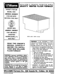
IMPORTANT
PRODUCT SOFTWARE DiSCLAIMER
such as brochures, drawings, technical data, operator's and workshop manuals,
Product software of all
parts lists and parts price lists, and other Information, Instructions and speCifications provided Irom sources
other than Westerbeke, Is no! within Westerbeke's controi and, accordingiy, is provided to Westerbeke customers only as a courtesy and service. WESTERBEKE CANNOT BE RESPONSIBLE FOR THE CONTENT
OF SUCH SOFTWARE, MAKES NO WARRANTIES OR REPRESENTATIONS WITH RESPECT THERETO, INCLUDING THE ACCURACY, TIMELINESS OR COMPLETENESS THEREOF, AND Will IN NO EVENT BE LIABLE FOR ANY TYPE OF DAMAGES OR INJURY INCURRED IN CONNECTION WITH, OR ARISING OUT
OF, THE FURNISHING OR USE OF SUCH SOFTV-JARE.
For example, components and subassemblies incorporated in Westerbeke's products and supplied by others
(such as engine blocks, fuel systems and components, transmissions, electrical components, pumps and
other products) are generally supported by their manufacturers with their own software, and Westerbeke
must depend on such software for the design of Westerbeke's own product software. Such software may
be outdated and no longer accurate. Routine changes made by Westerbeke's suppliers, of which Westerbeke rarely has notice in advance, are frequently not reflected in the supplier's software until after such changes take place.
Westerbeke customers should also keep in mind the time span between printings of Westerbeke product
software, and the unavoidable existence of earlier, non-current Westerbeke software editions in the field. Additionally, most Westerbeke products include customer-requested special features that frequently do no! include complete documentation.
In summation, product software provided with Westerbeke products, whether from Weslerbeke or other suppliers, musl not and cannol be relied upon exclusively as the delinitive authority on the respective product.
It not only makes good sense but is imperative that appropriate representatives of Westerbeke or the supplier in question be consulted to determine the accuracy and currency of the product software being consulted by the customer.
1
Westerbeke Generators
FOREWORD
Thank you for sel'scting a Wc"t<>rh"kA marine ",,'uU'C' for your use. We at Westerbeke are pleasE,d to have
you as a customer.
Read this manual carefully and observe all safety precautions included throughout Operating procedures,
periodic preventive maintenance procedures, installation checks, system descriptions and minor adjustment procedures are included herein so you can operate your equipment safely and properly, maintain the
equipment at a high level 01 efficiency, and expect dependable performance and long service life in return.
Should your unll require special attention, contact your Westerbeke dealer for assistance. The Westerbeke
Service Organization is trained to provide the support necessary to ensure long-term dependable performance.
If, within 60 days of submitting the Warranty Registration Form lor your unit, you have not received a Customer Identification Card (see below) registering your warranty, please contact the factory in writing with
Model information, including the unit's serial number and commission date.
from:
WESTERBEKE CORPORATION
AVON INDUSTRIAL PARK
AVON, MA 02322
WESTERBEKE
.,.",,, !~E,,~-r~I~t.
r"u.
M.t"l>I, fi* aZH1. •
'rELEX' "Z-HH· FAX: (bt7)
CUSTOMER I E
Tn. (61"
559"93;>;~' c,.~I,.~:
IFICATION
Adam Smith
Mail To:
85 Maple Street
Alden,
IN 12234
Model BTG 8.SKW
Expires 717/SB
Weslerbeke Generators
2
snS-77"'"
~~S'l'C~~?
Ser . • 1234(706
TABLE OF CONTENTS
Section
GENERAL
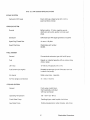
BTG 65KW GENERAL SPECIFICATiONS .. " ... "."." .... 12
SYSTEM SPECiFICATiONS
BTG 125KW GENERAL SPECIFICATIONS
SYSTEM SPECIFICATIONS " .. " ..... .
BTG 15.0KW GENERAL SPECIFICATIONS .................. " 20
SYSTEM SPECIFICATIONS." ......... " .. " ...... " ... "" ...... " .... 21
PREPARATIONS FOR STARTING ..... ".".""."." .. " ... " ..... 35
CARBURETOR AND FUEL SYSTEM
... " ..... 40
OPTIONAL REMOTE INSTRUMENT PANEL
.. "" ... "" ..
WIRING DIAGRAM # 35698
DC CONTROL CIRCUIT
WIRING DIAGRAM # 37190 ."."" ........... " ...... "" ...46 & 47
OPTIONAL REMOTE START PANEL
WIRING DIAGRAM # 35706 .................. .
COOLING SySTEM ....... "
LUBRICATION SYSTEM ..
GENERAL INFORMATION AND CARE
OF THE GENERATOR"
......................... " 65
ENGINE CONTROL PANEL.. .............. " .. ". 67
ENGINE TROUBLESHOOTING ............... " ...... ".69
WeslerlJeke Generalors
TABLE OF CONTENTS
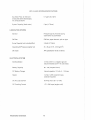
MAINTENANCE & ADJUSTMENTS., ,
LAY-UP & RECOMMISSIONING.,.,
".,,74
".,.".,.,82
TABLE OF STANDARD HARDWARE
TIGHTENING TORQUES ,.,.".,.,.".,." '
.,.,85
TABLE OF TIGHTENING TORQUES .,
.,,86
INDEX .,.".".".,.,., .,.,.,., ,., .,.,." ,.,." ,.,.,.,
",.,.,.,.,." .,,87
Weslerbeke Generators
4
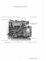
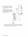
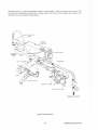
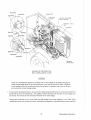
BTG 1l.!'iKW MarinI! Gasoline Generator
Fresh Waler Coolant Fill
Exhaust Manifold
0
45 Exhaust Elbow
Sea Waler Pump
DC Battery Ground
Connection
nit Data
Heal
lube Oil Dips,i
Starler
DC Circuit Breaker
Westerbeke Generators
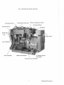
BTG 12.5KW Marine Gasoline Generator
all Fill
Fresh Waler Coolant Fill
Exhaust Temperature Swllch
45' Exhaust Elbow
Sea Waler Pump
Distributor
Tag
Heat Exchanger
Starter with Solenoid
DC Battery Ground
Conneclion
20 Amp DC Circuil Breaker
1
Weslerbeke Generators
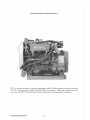
BTG S.5KW Marine Gasoline Generator
NOTE: At the time of printing. a right-side photograph ollhe BTG 8.5KW generator set was not available.
The BTG i 2.5KW generator is similar to the BTG 8.5KW in construction. Please reler to page 8 lor a rightsided view of the BTG 12.5KW generator set which illustrates the various generator components.
Westerbeke Generators
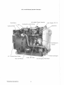
BTG 12.5KW Marine Gasoline Generator
Air Intake Flame Arrestor
Distributor
Top Engine Oil Fill
Carburetor
Pressure
IIC Connections Outlet
Alternator
Weslerbeke Generators
BTG 15,OKW Marine Gaso\;ne Generator
Top F"",;"" Oil Fill
Fresh Water Coolanl Fill
Exhaust TernperSI!U!'e Switch
45° Exhaust Elbow
Sea Waler Pump
Distributor
lube Oil Dipsli(:k
Slarler wilh Solenoid
20
DC BlltlelN Ground
Conneclion
DC Circuil Breaker
Weslerbeke Generators
BTG Hi.OKW Marine Gasoline Generator
Air Intake Flame Arrestor
Distributor
Coil
Oil Fill
Carburetor with Choke
Pressure
Switch
AC Conneclions Oulle!
Alternator
Weslerbeke Generators
10
GENERAL
Inlroduction
This manllai contains lhe equ1r)ment op'8n,tirlg proc:edul as well as additional information needed to
the
the marine
in proper wcwklnn
and follow the instructions carefully_ A
maintenance program is included in Ihis
~nihc"ir,,, 10lhe program will result in better
and
iife_
ril''''CI()cjc
is the most
slep
trC)Uilieshootinq lable is induded_
10 salisfac\oiry
the Gasolina Driven Generalo!
an AC
is in many ways sjm~!ar to a
automobile
Th.e
vertiea!
and the
head has an overhead camshaft v,;hich is chain-driven,
The
utHlzes a solid-state distributor which is
mounted and camshaft-driven.
lubrication
and a fresh waler-cooled
block which is thermo"'(1IIi:,I', the same ~~,,,,,mtiiHo ma!ntenance
thaI is '''''' ",(pr{ of a n,;"niinp
The most im:nn:rtp:nt factors lc the
are
proper ventiiiation, maintenance of the fuel sVCltern_ irmltion sy:stem_ m(1Iir:n n'J,f,Am and the nPhm-A;rw enol
The
c\fi'inrlMcare
VVheneV8r
are
the
mode! m :m(rM
serla! nurn·"
and
serfa~ number as
appear on the scariet and
located on the goner."
ator end.
must
us with this informaHcm so we may ptCJpE:rlv IdAn'iiv your
set in
include a
and
number for each
the
fur··
rdshed Parts
be sure to insist upon 'vVesterbeke
because wfff fit or nAnprl"
not made to the same
as ncilnlnAi C'Cluiipnn811i.
Note that nome-:m-,pc)! locations in the manual arB referenced from the front of the
which Is the
flywl-18Eil/Clcr:erslclf end is the rear
Left and
sides are determined
the
!n the same direction as the front of the
the left slde
is at your
Westerbeke
before
rl0n"i<~I,,,q
the
sets are
checked and
a final nm under various load cono;tlons
~A!rvi(cp and a satisfied owner
ThlS is done to ensure r1AnA;mi;,hIA operatim1,
Care at the
and
have resulted in a Westerbeke Do,on!inD Mni,'D_
driven
at many thousands
hours of
servlce~
the manufacturer
is up to the ()\Arnr;ri!1n(O,"tor
cannot controlls the treatmBnt the unit receives in the nBld. That
Weslerbeke Generators
BTG Its KW MARINE GASOliNE GENERATOR SET
GENERAL SPECIFICATIONS
Engine
Gasoline, lour-cycle, two-cylinder, fresh water-cooled
Vertical, in-line overhead valve mechanism
(18,5 hp at 1800 rpm maximum),
Governor
flybali type, 5% speed regulation
Combustion Chamber
Multi-sphere type
Bore & Stroke
2,76 x 2,74 inches (70 x 69,6 mm)
Piston Displacement
65,4 cubic inches (1,07 liters)
Firing Order
1-3-4-2
Direction of Rotation
Clockwise, when viewed from the front
Maximum Torque (at 1800 rpm)
51,3Ib-1t (7,1 kg-m)
Compression Ratio
9,2:1
Compression Pressure
(Umit of difference between cylinders)
170 psi (12 kg/cm £at 300 rpm
(2 8 psi [2,0 kg/em ])
Valve Timing
Intake Opens 15" BTOC
Intake Closes 44" ABOC
2
Exhaust Opens 53" BBOC
Exhaust Closes 6" ATDC
Valve Seat Angle
Intake 45"
Exhaust 45'
Valve Clearance
(engine cold)
Intake 0,0098 inches (0,25 mm)
Exhaust 0,0098 inches (0,25 mm)
Engine Speed
1800 rpm 60 Hertz
1500 rpm 50 Hertz
Dimensions
Height: 23,63 inches (600.20 mm)
Width: 18. 75 inches (476,25 mm)
Length: 31.50 inches (800,10 mm)
Weight
513 ibs (232.7 kgs)
Fuel Consumption
1.10 gph (4,16Iph) al full rated output (approximate)
Inclination
Continuous 15'
Temporary 20'
Westerbeke Generators
12
to exceed 20
BTG 11.5 KW SYSTEM SPECIFICATIONS
INTAKE
"""'T",n
Carburetor
type)
Down draft type, single barrel with U,S,C,G,
approved flame arrester.
IGNITION SYSTEM
Generel
Battery ignition, 12-Volts, negative ground,
distributor with points, ignition coil and spark
plugs.
Distributor
Solid state type with signal generator and igniter
Spark Plug Thread Size
14 mm x 1.25 pitch
Spark Plug Type
Westerbeke part number
033805
FUELSVSTEM
General
Conventional carburetor type with fuel lift pump
Fuel
Regular or unleaded gasoline with an octane rating
of 89 or better.
Lilt Pump
12-Volt DC; lift capacity 6 ft (1,8 m)
Fuel Screens (on engine)
Reusable screen type (one in Carburetor and one
in electric fuel pump),
Air cleaner
Metal screen type - cleanable
Air Flow (engine combustion)
35 elm (1.0 cmm)
COOLING SYSTEM
General
Fresh water-cooled block,
thermostatically-controlled
wtlh heat exchanger,
Operaling Temperature
130 - 150 F (55 - 66 C)
Fresh Waler Pump
Centrifugal type, metal impeller, bell-driven
Sea Water
PosITive displacement, rubber impeller, belt-driven,
0
13
0
Weslerlleke Generators
BTG lUi KW SYSTEM SPECIFICATIONS
Sea Water Flow, at 1800 rpm
(measured before discharging
into exhaust elbow)
6.7 gpm {25.3
System Capacity (fresh water)
5 qts (4.7 liters)
LUBRICATION SYSTEM
General
Pressure type by Trochoid pump,
chain-driven by crankshaft.
Oil Filter
Full flow, paper element, spin-on type
Sump Capacity (not including filter)
3.9 qts (3.7 liters)
Operating Oil Pressure (engine hot)
25 - 35 psi (1.75 - 2.50 kg/cm
Oil Grade
API
spec~ication
2
)
of SE or SE/CC
ELECTRICAL SYSTEM
Starting Battery
12-Volt, 26 A-H, (-) negative ground
(recommended) (35 A-H in cold areas)
Battery Capacity
90 - 125 (Ampere-Hours)
DC Battery Charger
Internal regulator 13 Volts, 0 -10 Amps.
Starter
12-Volt, 1.2KW, reduction type,
solenoid-mounted
DC No-Load Current
90 Amp (max.) at 11.5 Volts.
DC Cranking Current
175 - 200 Amps (engine cold)
Weslerbeke Generators
14
BTG ItS KW SYSTEM SPECIFICATIONS
AC GENERATOR
General
Brushless,
revolving field.
Pre-lubricated, single-bearing design.
Reconnectable, single-phase transformer regulation
(optional solid-state voltage regulation).
120 or 120/240 Volts - 60 Hertz
220 Volts - 50 Hertz.
Voltage regulation: ± 5% no load to
full load.
Frequency regulation: ± 3 Hertz (5%)
no-load to full-load.
Rating (Volts AC)
60 Hertz (1800 rpm)
120 Volts
120/240 Volts
70 Amps
70/35 Amps
50 Hertz (1500 rpm)
220 Volts
31 Amps
AC Circuit Breaker
To be rated at 120% of the generator's rated
amperage output and voltage
Generator Cooling
Air Requirements, (60 Hertz),
at 1800 rpm
200 - 225 elm (5.7 - 6.4 cmm)
NOTE: Increase air supply 15% lor 50 Hertz operation (1500 rpm).
Engine Combustion Air
Requirements, (60 Hertz),
at 1800 rpm
35 elm (1.0 cmm)
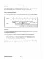
TUNE-UP SPECIFICATIONS
Spark Plug Gap
0.031 ± 0.002 inches (0.80 ± 0.05 mm)
14° ± 1° BTDC at 1800 rpm
15
Weslerbeke Generators
BTG 12.5 KW MARINE GASOLiNE GENERATOR SET
GENERAL SPECIFICATIONS
Engine Type
Gasoline. four-cycle, two-cylinder, fresh water-cooled
Vertical, in-line overhead valve mechanism
(22.5 hp at 1800 rpm maximum).
Governor
Hoof, flyball type, 5% speed regulation
Combustion Chamber
Multi-sphere type
Bore & Stroke
3.03 x 2.74 inches (77 x 69.6 mm)
Piston Displacement
79.1 cubic inches (1.296 liters)
Firing Order
1-3-4-2
Direction of Rotation
Clockwise, when viewed from the front
Maximum Torque (at 1800 rpm)
63.6 Ib-It (8.8 kg-m)
Compression Ratio
9.2:1
Compression Pressure
(Limit of difference between cylinders)
170 psi (12 kg/cm2~ at 300 rpm
(2 8 psi [2.0 kg/em J)
Valve Timing
Intake Opens 15' BTDC
Intake Closes 44' ABDC
Exhaust Opens 53' BBDC
Exhaust Closes 6' ATDC
Valve Seat Angle
Intake 45"
Exhaust 45'
Valve Clearance
(engine cold)
Intake 0.0098 inches (0.25 mm)
Exhaust 0.0098 inches (0.25
Engine Speed
1800 rpm 60 Hertz
1500 rpm 50 Hertz.
Dimensions
Height: 23.63 inches (600.10 mm)
Width: 18.75 inches (476.25 mm)
Length: 33.63 inches (854.20 mm)
Weight
5331bs (241.7 kgs)
Fuel Consumption
1.25 gph (4.73Iph) at lull rated output (approximate)
Inclination
Continuous 15'
Temporary 20' (not to exceed 20 min.)
Weslerbeke Generators
i6
BTG 12.5 KW SYSTEM SPECIFICATIONS
INTAKE SYSTEM
Carburetor (STD type)
Down draft type, single barrel with U,S,C,G,
approved flame arrester.
IGNITION SYSTEM
Genera!
Battery ignition, 12-Volts, negative ground,
distributor with points, ignition coil and spark
plugs,
Distributor
Solid state type with signal generator and igniter
Spark Plug Thread Size
14 mm x 1.25 pitch
Spark Plug Type
Westerbeke part number
033805
FUEL SYSTEM
General
Conventional carburetor type with fuel lift pump
Fuel
Regular or unleaded gasoline with an octane rating
01 89 or better.
Lift Pump
12-Volt DC; lift capacity 6 ft (1 ,8 m)
Fuel Screens (on engine)
Reusable screen type (one in Carburetor and one
in electric fuel pump),
Air cleaner
Metal screen type - cleanable
Air Flow (engine combustion)
41,1 elm (1.16 cmm)
COOLING SYSTEM
General
Fresh water-cooled block,
thermostatically-controlled
with heat exchanger.
Op'enltirlg Temperature
130 - 150' F (55 - 66' C)
Fresh Waler Pump
Centrllugallype, metal impeller, belt-driven
Sea Water
Positive displacement, rubber impeller, belt-driven.
Weslerbeke Generators
BTG 12""KW SYSTEM SPECIFICATIONS
Sea Water
at 1800 rpm
ITlE'ilsurcu before discharging
into exhaust elblowl
5
LUBRICATION SYSTEM
General
Pressure
Trochoid pump"
chain-driven by crankshaft.
Oil Filter
Full
paper "{,,,mAln! spin-on
Sump Capacity (not including Iilter)
Operating Oil Pressure (engine hot)
25 - 35 psi (U5 - 250 kg/cm2)
011 Grade
API specification 01 SE or SEICC
ELECTRICAL SYSTEM
Starling BgttelN
26
(-) negative ground
(recommended) (35 A-H in cold areas)
Battery Ca,laclty
90 -125 (An1pe,re-Ho{Jrs)
DC Battery Charger
Internal re,lul2uur 13
Starler
1.2KW, reduction type,
solenoid-mounted
DC No-load Current
90
DC Cranking Current
175 - 200
Westerbeke Generators
18
0-10
at 115 Volts.
(engine cold)
BTG 12J'i KW Sy,rrEM SPECIFICATIONS
AC GENERATOR
General
revolving fieid"
ReC0I1!1E,ctr,bl'8, Bllngle-Iehrrse transformer
120 or 120/240 Voits - 60 Hertz
220 Volts - 50 Hertz"
± 5% no load to
full load.
FrElouen,:v e'0W"WJH. -I 3 Hertz
no-load to fu!!-~oad"
60 Hertz (1800
120 Volts
120/240 Volts
50 Hertz (1500
220 Volts
AC Circuit Breaker
To be raled at 120% althe ""'1M81,)[', rated
47
amperage
Generator Cn,r,ilnn
Air Ro,quii(Orrlenlts
at 800 rpm
NQTE
incmase air
!:'nedrn
Combustion Air
and vollaels
220 cfm
5% for 50 Hertz op'3ralliofl (1500
(60
at 1800 rpm
41. clrn(1.113
TUNE-UP SPECIFICATIONS
0,031
i 8° ±
19
± 0,002 inches
BTOe at i 800 rpm
Weslerbeke Generators
BTG 15.0 KW MARiNE GASOLINE GENERATOR SET
GENERAL SPECIFICATIONS
Engine Type
Gasoline, lour-cycle, two-cylinder, fresh water-cooled
Vertical, in-line overhead valve mechanism
(27 hp at 1800 rpm maximum).
Governor
Hoof, ftyball type, 5% speed regulation
Combustion Chamber
Multi-sphere
Bore & Stroke
3.03 x 3.15 inches (77 x 00 mm)
Piston Displacement
90.0 cubic inches (1.48 liters)
Firing Order
1-3-4-2
Direction 01 Rotation
Clockwise, when viewed from the front
Maximum Torque (at 1800 rpm)
76.6Ib-ft (10.6 kg-m)
Compression Ratio
9.0:1
Compression Pressure
(Limit 01 difference between cylinders)
170 psi (12 kg/cm21 at 300 rpm
(28 psi [2.0 kg/em ])
Valve Timing
Intake Opens 15° BTDC
Intake Closes 58° ABDC
Exhaust Opens 5W BBDC
Exhaust Closes 15° ATDC
Valve Sea!
Intake 45'
Exhausl45°
Valve Clearance
(engine
Intake 0.0098 inches (0.25 mm)
Exhaust 0.0098 inches (0.25
Frle,i"" Speed
1800 rpm 60 Hertz
1500 rpm 50 Hertz
Dimensions
Height: 23.63 inches (600.10 mm)
Width: i 8.75 inches (476.25
Length: 33.63 inches (854.20 mm)
Weight
560 Ills
Fuel Consumption
1.6
Inclination
Continuous 15'
Temporary 20' (not to exceed 20 min.)
Weslerbeke Gel1erators
20
kg8)
(6.05 Iph) at full rated output (approximate)
BTG 15,() KW SYSTEM SPECIFICATIONS
INTAKE SYSTEM
Carburetor (STD type)
Down draft type, single barrel with U.S.C.G.
approved flame arrester,
IGNITION SYSTEM
General
Battery ignition, 12-Volls, negative ground,
distributor with points, ignition coil and spark
plugs.
Distributor
Solid state type with signal generator and igniter
Spark Plug Thread Size
14 mm x 1.25 pitch
Spark Plug Type
Westerbeke part number
033805
FUEL SYSTEM
General
Conventional carburetor type with fuel lilt pump
Fuel
Regular or unleaded gasoline with an octane rating
01 89 or better.
Lift Pump
12-Volt DC; lift capacity 6 It (1.8 m)
Fuel Screens (on engine)
Reusable screen type (one in Carburetor and one
in electric fuel pump).
Air cleaner
Metal screen type - cleanable
Air Flow (engine combustion)
47 elm (1.3 cmm)
COOLING SYSTEM
Generai
Fresh water-cooled block,
thermostatically-controlled
with heat exchanger.
_66"
Operating Temperature
130-150°1"
Fresh Waler
Centrifugal type, metal impeller, belt-driven
Sea Water
Positive displacement, rubber impeller, belt-driven.
21
Weslerbeke Generators
BTG HHI KW SYSTEM SPECIFICATIONS
Sea Water Flow, at 1800 rpm
(measured before discharging
into exhaust elbow)
7 gpm (26.5
System Capacity (fresh water)
1 q!s (6.6 lilers)
LUBRICATION SYSTEM
General
Pressure type by Trochoid pump,
chain-driven by crankshaft.
Oil Filter
Full flow, paper element, spin-on Iype
Sump Capacity (not including filter)
3.9 qls (3.7Iilers)
Operating Oil Pressure (engine hot)
25 - 35 psi (1.75 - 2.50 kg/cm 2)
Oil Grade
API specification of SE or SE/CC
ELECTRICAL SYSTEM
Starting Battery
12-Volt, 26 A-H, (-) negative ground
(recommended) (35 A-H in cold areas)
Batlery Capacity
90 - 125 (Ampere-Hours)
DC Battery Charger
l!llemal regulator 13 Volts, 0 -10 Amps.
Starter
12-Vol!, 1.2KW, reduction type,
solenoid-mounted
DC No-Load Current
90
DC Cranking Currenl
175 - 200 Amps (engine Gold)
Wes!erbeke Generalors
22
(max.) at ii.5 Volts.
BTG 1!Ul KW SYSTEM SPECIFICATIONS
AC GENERATOR
General
Brushless,
field.
Pre-lubricated, single-bearing design.
Reconnectable, single-phase transformer regulation
(optional solid-state voltaga re,jUl,wu'''I.
120 or 120/240 Volts - 60 Hertz
220 Volts - 50 Hertz.
Voltage regulation: ± 5% no load to
!ullioad.
Frequency regulation: ± 3 Hertz (5%)
no-load to lUll-load.
Rating (Volts AC)
60 Hertz (1800 rpm)
120 Volts
120/240 Volts
124 Amps
50 Hertz (1500 rpm)
220 Volts
60 Amps
AC Circuit Breaker
To be rated at 120% 01 the generator's rated
amperage output and voltage
Generator Cooling
Air Requirements, (60 Hertz),
at 1800 rpm
124/62 Amps
250 - 275 elm (7.0 - 7.8 cmm)
l'lQIE: Increase air supply 15% lor 50 Hertz operation (1500 rpm).
Engine Combustion Air
Requirements, (60 Hertz),
a11800 rpm
47 elm (1.3 cmm)
TUNE-UP SPECIFICATIONS
Spark Plug
0.031 ± 0.002 inches (0.80 ± 0.05 mm)
Timing
18° ± 1° BTDC at 1800 rpm
23
Weslerbeke Generators
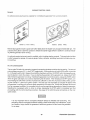
INSTALLATION CHECKS
General
Since the crafts in which Westsrbeks generators are installed vary in design, installation procedures will vary
according to your craft's specific design. The intent of this seclion is not to advise boatyards or installers on
procedures already well-developed and well-understood. However, it is important that the owner/operator
realize there are details of the installation which require periodic checks 10 ensure Ihe best operating conditions for the equipment and safe operating conditions lor the personnel on board. Proper location and installation of the gasoline generator in the vessel are 01 prime importance.
Factors in the installation that must be considered are ventilation, to aid in cooling the generator end; to
provide air for engine combustion and to remove heat produced by the engine while operating; the exhaust
system, to properly discharge raw cooling water (sea water), to quiet the exhaust, and to expel exhaust gas;
the cooling water supply; and the electrical connections.
CAUTION
For safety reasons, the generator's engine is NOTfilied with lubricating oil for shipment. Before
leaving the factory, however, each generator set is thoroughly tested with oil in ITS engine.
This testing, among other things, provides all internal parts with a coating 01 oil. This oil acts
as a preservative, providing reliable protection against corrosion for at least one year if the
generator is properly stored.
Inspection 01 Equipment
The generator is shipped from the factory securely mounted and properly crated. Accessory eqUipment is
shipped in a separate small box, usually packed within the generator's crate.
Before accepting shipment of the generator set from the transportation company, the crate should be opened
and the contents inspected for concealed damage. If either visible or concealed damage is noted, you should
require the delivery agent sign "Received In damaged condition" on the proper delivery receipt. Also check
the contents 01 the shipment against the packing list and make sure that the proper notation is made if any
discrepancies exist. These noted discrepancies are your protection agalns! loss or damage. Claims concerning loss or damage must be made to the carrier, not to the Westerbeke Corporation.
Westerbei<e Generators
24
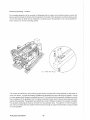
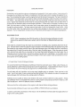
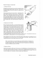
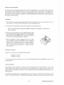
The generator is lilted w~h lifting eyes. Rope or chain slings capable 01 supporting the generator"s weight
should be attached to the eyes and the generator lilted by means of tackle attached to lhese slings. The lifting eyes have been designed to carry the lull weight of the generator; therefore, auxiliary slings are not required or desired.
Slings must not be so short as to place significant stress on the generator's lifting eyes. Strain
placed on the generator's lifting eyes by the lifting sling must not be in excess 0110° from the
vertical plain.
~
10'
~
SLlt-iC !..IFTIHG
A>lGU: MUST NOT
EXCEEO la'
LIfTING
EYE
ENGINE
The general rule in moving generators is to see Ihat all equipment used is amply strong and firmly fixed in
place. Move the engine a little at a time and see that it is firmly supported. Eliminate the possibility of accidents by avoiding haste. Do not lift Ihe generator by its crankshaft puiley. In certain situations it may be
necessary to lift the engine in positions other than lhe horizontal position. Certain situations exist by which
the engine must be lowered endwise
a small hatchway which cannot be made larger, Under these
conditions, II the opening 01 the hatchway is ex1remely small, it is possible to reduce, to some ex1ent, the
outside dimensions of the generator by removing ex1emal components such as the alternator, the cooling
system's piping, the heat exchanger, certain filters, the mounting rails and other obstructive equipment This
accessory equipmell! should be removed by a competent mechanic and special care should be taken to
avoid damage to any exposed parts. In addition, be careful not to allow dirt from enlering any opening
created by the removal 01 equipment Removed parts should be returned to their respective position as soon
as the generator has cleared the hatchway.
In case it becomes necessary to hoist the generator Iront-end upwards or generator-end upwards, the attachment of lifting slings must be done carefully to avoid the possibility 01 damaging the parts on which the
weight of the siings may bear. Special rigging work is best done by someone experienced and competent
in handling heavy machinery.
25
Weslerbeke Generators
Generator
M()urlllrig -
localion
com,llel:e fl,nemlor unIT Is mounted 011
rails
means 01 four flexible isolator mounts thai
tr~n"fA' of vibration from the
rails. Each
rail has several
1/2-lnch boll holes so bolts can be employed to properly secure the ne,ner'atCl(
These holes are on 15 inch
centers.
(1!2~
MOUMTIMG HOLES)
The location should be dry, above low-lying vapor areas, and away from
splashed by bilge water or
water from above. It should be property ventilated and accessible for minor servicing and repairs. Access
for major repairs should be given consideration as well. The location should be properly ventilated to provide
fresh cooling air for the generator end, lor engine combustion needs, and 10 remove heat produced by the
engine while operating. The generator set needs Iresh cool air in whatever location in the vessel it is installed.
Hot generator discharge air must be removed from the generator area. The platform on which the gener·
ator and its mounting rails are localed should be slrong
to support the generator during all angles
of vessel operation.
Weslerbeke Generators
s
(ThiS page replaces the same page in the Operator's Manual)
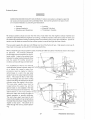
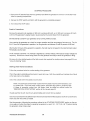
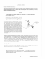
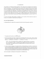
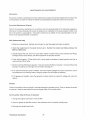
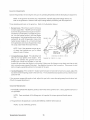
Governor Adjustments
Operate the generator set to bring the unit up to its operating temperature before attempting an adjustment.
NOTE: If the governor is severely out of adjustment, manually adjust the linkage without any
load on the generator to obtain a safe output voltage before proceeding with the adjustment
Three adjusting points are on the governor. (Refer to the illustraiion below.)
1. !lumper SQtlYJI This screw is used to remove
a
no-load surge ONLY. NEVER turn the bumper
screw into the governor far enough so that it increases the no-load speed. To adjust the governor, turn the bumper screw in until the engine
stops surging.
Now bring the Increase/Decrease Speed Screw (on the governor) up ur:til the generator runs between 61.5 to
62.0 cycles no-load. Applya 1/4, a 1/2 and a 3/4
load to the generator and ensure the generator
does not surge under these three load intervals.
LINKAGE A'"
SCREW
NOTE: Only If the generator surges at any
of these load intervals are you to follow
steps #2 and #3 below.
HUNTINGI
REGULA! ION
ADJUSTMENT
INCREASE/DECREASE SPEED SCREW
CARBURETOR THROTTLE LEVER
2. IncreaselDecrease Speed This adjusting bolt
sets the no load speed of the engine. (The
linkage arm between the governor arm and
throttle lever should be adjusted to hold the throttle full open when the engine is not running.) Make sure
this linkage moves freely and that the ball joint connectors are properly lubricated. Use graphite lubricant
at this connection. Disconnect the bal! joint and apply a graphite lubricant to the inside of the joint.
3.
Hlmtln~/ReQIJ18tion
If the variation in engine speed between no load and full load is too great, adjust this
eye bol, 10 draw the spring closer to the lever hub. The increaseidecrease speed bolt may need to be adjusted as well.
the speed adjustment.)
Speciai Note: On page 8i, under Spark Piugs, the engine must be caid when the spark plugs
are removed. Removing spark plugs from a hot engine can pull the threads out of the cylinder
head.
Vi esterbeke Generators
78
CARBON MONOXIDE EXHAUST GAS IS DEADLY. Carbon monoxide is a dallqE!rollS gas tilat
can cause unconsciousness and is potentially lelhal. Some oltha ~Vlnn!mnR or
of carbon monoxide Inhalation or
are listed below.
o Dizziness
o Intense Headache
o WeaKness and Sle,,'c,i""RS
o
Vr,mitinn
o Muscular
o
In T 81:np!es
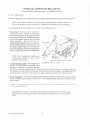
All exhaust
should he such that the
of sea waler into the engine's exhaust manifold and
is not running, or while the vessel is under sailor power in which case
cylinders is
while the
the vessel may
healing or backing down from following seas or any other conditions. Special atis secure and tight and free of leaks.
tention mllst be made to ensure that the exhaust
The sea water supply thru-hull sea cock fittings must be 01 the flush-hull
lings must not be used, as
lend to encourage dnh,ynlnn
When a water lift
exhaust system is
as
The exhaust
should
downward into the exIn the exhaust hose
haust muffler.
between the
exhaust elbow
and the water lift muffler should be
,M)IDeO, as these will
and hold water.
Hiclh-';oE,ed scoop type fit-
the exhaust muffler should be mounted as close to the engine
For installations where the
al or below Ihe vessel's water
must be made to install a
,irlhrln-I'",>;;w or a vent in the sea water
SIJUDIV hose to the
exhaust
the flow of sea water
elbow. This
thai runs
the sea water co'olirlg
Sv';IAIm from
the exhaust and !'l1m'l"
,vlir"',,,', when the
is shut down.
hose must be
This sea water
above the wal:er line and
sic,hon-IJre,,,k or vellt Instalied in the
above the water line.
point of the
sir,hnr1-l""Aw or vellt
above the waler line
vessel
to "",,"m' dn.hnnirln
The
when used, must have its vellt
hose or tube routed so ~ can remain above
the water !Ine and empty 01 water when the
engine is shut down. This allows air to
lhis vent to prevent slohmlenter
SUi WAIH
SHI,lH~
21
Westerbeke Generators
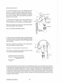
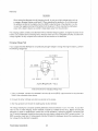
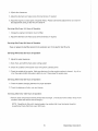
Exhaust Back-Pressure
The exhaust discharge hose must be 01 adequate size and
minimal run to prevent excessive exhaust back-pressure.
Exhaust back-pressure should be checked before a generator is put into service. (Refer to the Illustration.) Excessive
back-pressure will affect the engine's performance and lhe
generator's power output.
To measure lor back-pressure, use a mercury manometer, a
pressure gauge, or a waler column. A boatyard or marine
mechanic should have a manometer or a pressure gauge.
""
"
"
Measure the engine's back-pressure at the exhaust elbow
while the generator is under a lull load.
./ Exhaust
Reier to the pressure specifications below.
Mercury
Manometer
\
A water column can be made by taking a clear plastic tube
and taping Oile end 01 the tube along a yardstick and fitting
the other end of the tube with a 1/4 inch NPT (National Pipe
Tap) pipe litting.
Measure the engine's back-pressure at the exhaust elbow
while the generator is under a lull load.
'-"
Dimension A cannot exceed 39 inches 01 water.
Back pressure, as measured by a gauge instrument, should
not exceed the following specifications:
3 inches of mercury (0.104 kgicm2)
39 inches 01 waler in a water column
(.099 kglcm 2 at 4 0 C)
22 ounces psi
1 1/2 psi
\
Excessive back-pressure can be caused by a small diameter exhaust hose, a small muffler, sharp bends in
lhe exhaust hose, improper fittings, water pockets, and a high volume 01 water in the exhaust system due
to the length of the exhaust discharge hose. The use of elbows and fittings in the exhaust discharge hose's
routing should be limited since these will create flow restrictions and contribute 10 exhaust back-pressure.
The generator's exhaust system must be separate from any other engine's exhaust system. Dry portions of
the exhaust system between the engine's exhaust manifold and the water injected exhaust elbow must be
insulated to hold in the heat
Weslerbeke Generlltonl
211
st,'Ck:~l~'pe
exhaust
must be attached to Ihe generator engine's ex~
hausl manifold by means 01 a flexible
connector pipe. This system must be
properly supported and insulated to
prevent water from entering inlo the
engine's cylinders. Provisions must
be made lor discharging the
engine's cooling sea water.
khn"m 10 the
Se:R WATe:R
:tMTRI<E ltll'lt.!_
.. U .... L ,.XT.:£: .. .::
URY STACK EXHAUST
E)(haust System Failures
When the engine's sea water is led into an exhaust system so that the lull stream of this water strikes a surface, erosion lakes place. This erosion may cause premature failures. The proper design of either a water
jacketed or water injected "wet" exhaust system to prevent this problem requires that the sea water inlet be
positioned so that the entering stream 01 sea water does not directly strike a surface. In addition, the velocity
of the entering sea water stream should be as low as possible, which can be achieved by having inlet fittings
as big in diameter as possible.
The besl protection against carbon monoxide pOisoning is a daily inspection of the complete exhaust system. Check for leaks around manifolds, gaskets, and welds. Make sure exhaust lines are not heating sur~
rounding areas excessively. If excessive heat is present, correct the situation immediately. If you notice a
change in the sound or appearance of the exhaust system, shut down the unit immediately and have the system inspected and repaired at once by a qualified mechanic.
Make sure there are no unnecessary objecls suspended from any portion of the exhaust lines. Excessive
weigh! could cause deflection or distortion of the lines, resulting in damage or leal<s. Inspect insulated portions of the exhaust system to ensure there is no deterioration of the insulation.
the
Prolonged
intenlsls wilhoullhe engine starting clln result in
mounted exhausi syslem with sell Wilier coolant This may
because the sea
Wilier pump is pumping sea waler Ihrough Ihe sell water cooling
during crank·
ing. This Silil water clln enter Ihe engine'S cylinders
way of Ihe exhausl manifold
once the exhaust
fiUs. Prevent this from
the sea water
supply Ihm-hull
drainlhe exhaust muffler, and correcllhe cause for the excessive engine crllnking needed 10 oblain II start.
from Ihis
of sell waler
is not a warrantable issue; Ihe
should
this in
mind.
Westerbeke Generators
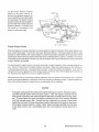
Fuel SVllle.11
The generator must have its own fuel supply
In other words, il must have Its own
tubes and
primary IiIter/water separator. DO NOT tee off another engine's fuel supply. Installations where the fuel
tank(s) are at or above the generator, with the fuel suppiy lines to the engine's carburetor routed below Ihe
level of the fuel lank's top, must have a means of shutting off the luello !he generator's engine when the engine is not running. This Installation procedure helps guard against !he possibility of gasoline siphoning
through the supply line into the engine through the carburetor, should the carburetor !Ioat needle valve stick
in the open position or not seat properly, or should the fuel line rupture between the engine and fuel tank.
This (anti-siphon) shut-olf valve can be electrically-operated (with a manual override) to open when the generator's engine is started, and closed down. A manually-operated valve can also be Installed and should be
operational from the generator's slart/stop panel or from the vessel's deck. Installations where the generator is located above the luel tank(s), whereby the routing of the fuel supply line to the generator's carburetor
remains above the top level of the fuel tank, do not require this (anti-siphon) shut-off valve. A manuallyoperated service shut-off valve should be located between the fuel pickup at the tank and the service shutoff valve located at the fuel connection to the generator.
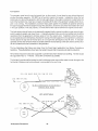
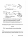
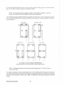
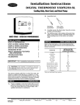
The two Illustrations that follow were taken from the Coast Guard publication Fuel System Compliance
Guideline. These illustrations show basic fuel system layouts that incorporate anti-siphon protection.
All fuel lines should be routed and supported to prevent leaks from vibration and chaffing. The line should
be supported every 12 - 14 inches. Use as few connections as possible.
The fuel tank's vent should be located so that its discharge route cannot allow water to enter through to the
fuel tank(s). Moisture must not be allowed to accumulate in the vent's line.
fUEL lilE ILMIYS •• OUE fUEL 'III 10. LEUEl
FUEL TANK TOP LEVEL
~
~---=~~~~~~
--(:.
~ :E~
~
NO A-A'-I---S r-'-HOK-aE-V r-,-[-.-. r-l-E-(-I I-r(-A-ll Y ~
a.EIIIEO VILUE IEEIEI
NOT ACCEPTABLE
fUEL
FUEL riiOC TB. LEUEL
fUEL
HNI
Weslerbeke Generator!!
3()
FUEL LIME BELOW FUEL TANK TOP LEVEL
AHTI-SIPHOW OEVICE OR ELECTRICALLY OPERATED FUEL STOP
VALVE AT fUEL lANK WITHURAWAL FIITING
ANTI-SIPHON 3EVICE OR ELECTRICALLY
FUEl lANK
I
rop LEVEL
IOPERATEO FUEL STOP VALVE
FUEL LINE ABOVE FUEL TANK
_t___I_OP ~ E~V~E~L~_-::-=~::__~::-=.::-:=-::C~
FUEL LINE BELOW FUEL TANK
TOP LEVEl
RNTI-SIPHON DEVICE OR ELECTRICALLY OPERATED FUEL
STOP VALVE AT POINT WHERE FUEL OISTRIBUTION LINE
GOES BELOW FUEL TANK TOP LEVEL
NOTE: The use 01 mechanical spring type check valves instead 01 a solenoid shut-off valve is
not recommended, as these may tax the luellift pump's ability to draw luel through a check
valve. A check valve can trap debris under its seat which inhibits the valve's ability to close.
In addition, if a check valve's cracking pressure is too high, IT may cause vapor lock.
Should a mechanical type, spring-loaded check valve be used, it should be of an adjustable
type (that Is, a Weatherhead #43 x 6). This adjustable type 01 valve should be adjusted to have
a cracking pressure so as to prevent siphoning when the generator is not operating.
Strongly recommended is the installation 01 an approved filterlseparator in the luel supply between the fuel
tank and the generator's engine to help remove contaminants in the fuel before the fuel reaches the enginemounted fuel lift pump and carburetor.
IWARNINGI
Gasoline leakage in or around the generator compartment is a potential cause of fire andlor
explosion. Repair leaks promptly and ensure that the compartment is properly ventilated.
Oil Drain
An oil sump drain hose is installed on the engine with the discharge end secured by a bracket at the front 01
the engine. Oil may be drained Irom this hose by removing the cap and Ihe discharge end 01 the hose from
the support bracket and lowering the hose into a container. The hose cap fitting is 114 inch NPT (National
Pipe Tap) and can be extended, or have a pump added, lor easier removal 01 the old oil, if desired.
Weslerbeke Generators
Make sure
intake system (sea waler
system) is in proper order. ChecK that the hull inlet, sea
cock and strainer are unobstructed, Sea cocks and strainers should be at least one size greater than the
inlet thread of the sea waler pump, The strainer should be 01 the type thai may be withdrawn lor cleaning
while the vessel is at sea and should be mounted below the water line to ensure self-priming, Inspect the
sea water lines to ensure there are no collapsed sections, which would restrict water flow, Make sure there
are no air leaks at any 01 the connections,
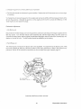
Coolir'Q System
The generator's engine is fresh water cooled by an engine-mounted heat exchanger. Sea waler is used as
the heat exchange's cooling medium, Sea water is
pumped into the exchanger by a sea water pump and
is then injected into the exhaust discharge, carrying
with it the heat removed from the engine's fresh water
cooiing system.
Sea water should be supplied to the sea water pump
through a flush-type hull fitting using a wire-reinforced
hose between the thru-hull fitting and the sea water
pump, This sea water should be directed through a
visual-type sea water strainer and then delivered to the
pump, Hoses routed from the thru-hull fitting to the
strainer and to the sea water pump should be wire-reinforced to prevent the hose from collapsing during the
generator's operation (suction from the pump may collapse a non-reinforced hose), Sea water strainers
should be mounted at or below the water line to make
sure the sea water line remains primed,
BUT TENSION
3/8-112 INCH
OEFlHTIIHi AT
lOKGEST spa"
CAUTION
Do not use a scoop-type thru-hull fitting as a means of supplying sea water to the generator.
Water pressure against this type lilting, while the vessel is under way, can push sea water past
the sea water pump's impeller into the generator's exhaust system, filling it and the engine as
well. Flush-type, clear, thru-hull fittings are recommended and should be iocated on the hull
so as to be below the waterline during all angles of boat operation,
The use of common-type street elbows is not recommended for plumbing the sea water circuit These
generally have very restrictive inside diameters, Machined fittings are preferred,
Electrical System
The electrical system shOUld be checked to ensure that all wiring harnesses are properly tied down with
clamps or plastic ties and that ali wiring harnesses are spaced at inleNals close enough to prevent chafing
from vibration, Check to ensure that all engine harness connections are tight and that they are made to the
appropriate terminals,
Westerbeke Generators
32
DC Elect!'ical Connections
A common
for the
DC terminal connection is found al the
of the oenet'atclr
next to the starter, in the form of a threaded
stud, The
ground should be connected at
this stud,
Connect the l'mltmv'< pO:;ili\!e
) connection to the slartsr solenoid la,)gE:d for this connection,
To avoid an OV'3rcna,
possiible RrllrimTIAI1t failure, DO NOT disconnect
the DC
source while the pnnin", is I WI! WilU,
The generator set must be grounded to comply with United States Coast Guard regulation 33CFR-183 which
specifies that a common conductor be connected bet-Neen the generator set and the vessel's main propulsion engine's
starter motor circuit This conductor (the common ground) prevents accidentai passage of
current through fuel systems and smaller electrical conductors common to the engines.
This conductor must be the same size as the largest battery cable,
Automatic Shutdown
Shutdown Switch (normally closed)
!c;nperiltuC8 switch is iocated on the exhaust elbow. This switch wil! open and
the DC
inn.rlin.n coil (which turns OFF the
should the switch's sensor indicate an excessive
exhaust lerno'''''!l
(an
supply of sea water coolant causes
exhaust
This
switch opens at 260 - 270" F (127 - 132" C), This switch resets at approximately 225" F (107" C).
Water T01TIp'''81Ure Shutdown Switch (norm;,'lvclm;edJ
A
water tetTIper<llure switch is located on the thermostat
This switch will open and
the DC
to the
COil
turns OFF the
shouid the fresh water COOlant's nhM'lti"·,,
telnpeHllLim reach
205" F
This switch resets at 195 F (lOr C),
0
Low Oil Pressure Shutdown Switch (nrmr1RII"v
A iow oil pressure shutdown switch is located oli the A"'linp', oil
P1'l11i1'lP'noH
pressure, Should the
nRIIAI'\! The switch's sensor monftors the
oil pressure fa!! to iO - 15
the switch Villi open UIl''''IUIl out
the DC voltage to the ignition coil (which turns OFF the ,m"in,,)
pnninp'p
RPM Shutdown Switch
An nV"""1CIM shutdown switch shuts oli the (l"'OprRte" set
reach
2175 rpm,
cut the
innoftir;n ~',j0t,"m
should the
Wesletbeke Generators
Generator
and in accordMake sure thet the AC output connections within the generator's distribution box are
ance with the specific AC Load Connections diagram found later in this manual. (See the 'BT GENERATOR'
section of Ihis manual, page 56.)
Do not smoke or allow an open flame near batteries. Lead acid batteries emit hydregen, a
highly-explosive gas.
Balterles
Make sure the positive ( + ) battery connection is connected to the battery connection of the starting solenoid.
The negative (-) battery connection should be connected to the system ground (the engine block).
When servicing the battery or checking the electrolyte level, wear rubber gloves, a rubber
apron, and eye protection. Battery acid may splash on the skin or into the eyes inadvertently when removing the electrolyte caps.
Check the battery's electrolyte level and specific gravity to ensure maximum engine starting efficiency. Make
sure the battery's terminals are clean and tight.
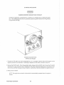
Ventilation
The ventilation requirements 01 the generator sets include the following: combustion air is required lor the
engine cylinders; cooling air is required lor the generator end and also lor removing the heat produced by
the generator's engine during operation; and ventilating air is required to clear the bilges below the generator, as well as the compartment in which the generator is located, of potentially toxic and lIammable diesel
fumes. Refer to the "SYSTEM SPECIFICATIONS" section 01 this manuai for the airflow requirements 01 the
generator sets, page 13 forthe BTG 8.5KW, page 17 forthe BTG 12.5KW, and page 21 forthe BTG 15.0KW.
Weslerbeke Generators
34
PREPARATIONS FOR STARTING
This section ollhe manual nrrlvirl"" lhe
with prepallalion, initial
starting
or
Follow the prc)cedures as nr_!~"'nIArl for the condilions indicated, and
you reliable
and
service life,
described below in starting your A,,,,,in<" for the firs! time or after a prolonged shutdown or lay,
Fill your
WITh oil up to or near the upper limi! on the
installation angle 01 your generator
set may have an effect on the dipstick
Select a readily available
oil with an API specifica,
tion of SC or SO and an SAE number suitable for the temperature in your operating area (see page 54), For
the
of oil needed in your generator's engine, refer 10 the "SYSTEM SPECIFICATION" section of Ihis
manual, page 14 fOrllla BTG R5KW, page 18 iOrille BTG 12,5KW, and page 22 for the BTG 15,OKW,
Each unit is supplied with a coolant recovery kit (part #24977) as standard equipment, to which the following applies:
A, Remove the pressure cap from tile engine's exhaust manifold and slowly fill the engine's cooling system with a mixture 01 water and antifreeze suitable for your temperature zone, (See the "COOLING SYS,
TEM" section of this manual, page 50,) Replace the pressure cap on the manifold,
EI, Make sure the plastic recovery tank is properly mounted near the unit (with the bracket provided) in a
location where it can be monitored and filled easily (see page 50), The recovery tank should be mounted
at manifold level or above,
C, Coolant should be added to the plastic recovery tank after lhe engine has been filled and started, After
its operating temperature has been reached, ensure tllat all air is expelled out of the engine's manifold
and the engine's cooling system, With the manifold filled and the pressure cap installed, fill Ihe plastic
recovery tank half full. Monitor this recovery lank daily and add coolanl as needed,
Fill the luellank with unleaded or leaded gasoline thai has an oclane
01 89 or better.
Ensure that the Installation Checks have been made In accordance wtth those specified in the "INSTALLA,
TION CHECKS" section of this manual
to page 24) and that there is no AC load on the generator,
35
Westerbeke Generators
STARTING PROCEDURE
CARBON MONOXIDE EXHAUST GAS IS DEADLY
Ventilate the
for a minimum of 5 minutes
to
the gener~
atar, The ventilating blowers remove n"jj.,nti~I!'" e;<pi,)si'/e gas()lin,efumes from the "Pln,,,',,tr,,
(C",nn,"rt,nA,nt and bilge,
ON
Standard Instrument Panel,
Switches and GaugE;s
i, Depress the ON switch and hold it depressed lor 5 to 15 seconds to ensure that the fuel sv,;teITi orllne
engine Is
to the carburetor,
to depress the ON switch,
to
#2,
2, Depress the START switch, When the generator starts, release
START switch,
ON switch
depressed lor a few seconds longer. (Keeping the ON switch
bypasses the oil pressure shut~
down circuit until the oil pressure rises enough 10 override the circUIT and maintain the inrlitirln
3, Release the ON switch,
NOTE: The I';nclinp has an electric choke which is
started,
Westerbeke Generators
:Ill
ItolTla!iCillly nn,'raIAfi when the Pl1clinA is
When starting Ihe
it is recommended thaI all AC
large molars, be switched OFF
until the
has come up 10
in cold ciirnales, starts 10 warm up, This
will prevent
r!~rn"rIA caused
the
and will
a cold
from stall,
""",In,.·
P",ln'''flM cralnkln(! imenll!l!l without the
clln result inlilling the
mounled exhllust system with lIeli Wilier C()Olllnl, This may
beclluse the sell
system
crankWilier pump is pumping sell wilier through the sel! wilier
way of the exhllust manifold once
ing, This sea waler ciln enler Ihe engine's cylinders
Ihe !!xh!!ust system fills. Prevent!hi:> from hllppening by closing Ihe sell waler supply
Ihm-hull shul·off, drainlh!! exhausl muffler, and correcllhe cause lor the excessive en·
gine cranking needed !O obtain a slart. Engine damage resulting Irom this type of sell
waler entry is !'lola warrllntable Issue; the owner/operator should keep this in mind.
Once the engine starts, check instruments (if Instruments lire installed) for proper oil pressure and battery
charging voltage. Never attempt 10 engage the starter while the engine is running. Apply a light load to the
to come up 10110 - 120" F (44 ' 49' C) before ap'
generator lind allow Ihe engine's operating
plying any heavy loads.
NOTE: Some unstable
may occur in a cold engine, but this condition should smooth
Oil! as the operating tAn1ne'rallure is reached
' 1500 F
,660
and when a load is ap'
to the aerlerE!tor
37
Westerbeke Generators
STOPPING PROCEDURE
1, Remove the AC electricallcad from the generator and allow the flA,n",'Rir)f to run lor 3 to 5 minutes to stebilize its operating ternp,eratures,
2, Depress the STOP switch and hold il until the generator is completely stopped,
3, Now release the STOP switch,
Break-In Precautions
Because the generator set operates at 1800 rpm to produce 60 Hertz, or at 1500 rpm to produce 50 Hertz,
control of the generator's engine break-in is governed by the current drawn from the generator,
Do not attempt to break-in your generator set by running it without a load,
Upon starting the generator set, check for proper operation and then encourage a fast warm-up, For the
first 10 hours of the generator's operation, run the generator set between 20 and 60 percent of lull-load,
After the first 10 hours 01 the generator's operation, the load may be increased to the rated lull-load output
Periodically vary the load,
Avoid overload at all times, An overload is signalled by a smoky exhaust, with reduced output voltage and
frequency, Monitor the current being drawn from the generator and keep it within the generator's rating,
8e aware of motor starting loads and the high curren! draw required for starting motors (see page 65 lor an
"Amps for Starting" chart),
Starling Under Normal Conditi()ns
Follow the procedure below for routine starting of the generator:
Check the engine's lubricating oil level prior to each day's use, Add oil as needed and maintain the oii level
at the high mark on the dipstick,
Check the coolant level in the plastic recovery tank,
NOTE: Excessive loss 01 fresh water coolant from the plastic recovery lank indicates a cooling system leak, Check the entire cooling system; pressurize the system to locate the leak
In cases 01 excessive coolant loss, Ihe system must be refilled as outlined under the
"PREPARATIONS FOR STARTING" section 01 this manual, page 35,
Visually examine the unit; look lor any abnormalities and correct them as needed,
Checkto ensure thatlhere is sufficient fuel in the tank and examine the filter/separator bowls lor contaminants,
Clean and drain the bowls as needed,
Start the generator, following the procedure outlined in the "STARTING PROCEDURES" section on the previous page, and allow lhe engine's operating temperature to reach 130 - 150" F (55 - 66" C) before placing
the generator under a heavy load,
Weslerbeke Generlliors
311
Under
cold tenlpE,ratuFE'S, the
condttlol1s can occur. Follow the instmctlons listed below
when operating your
sel in cold weather
oil used conforms with the ratings
LUBR!CATING OIL TURNS VISCOUS - Make certain that the
lor the
atmospheric temperature. Refer to the "LUBRICATION SYSTEM" section 01 this manual,
page 54, lor an atmospheric/oil viscosity
table.
VOLTAGE ACROSS BATIERY TERMINALS DROPS - Make certain thallhe battery Is fully charged to minimize voltage drop across Ihe battery terminals.
39
Weslerbeke Generators
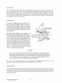
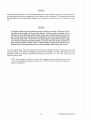
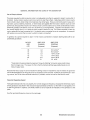
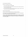
CARBURETOR AND FUEL SYSTEM
Gasoline
Use unleaded or leaded gasoline with an octane
01 89 or belleL
In cold weather particularly, water vapor is
by condensation when air is
Keep fuel tenk(s) full and completely free of dirt end water
The carburetor is a
m","",,' in the luel tank,
barrel down draft type with a metal screened air intake filter which is cleaneble,
seRE ENEO
AIR
CHAMER
\\-t-Y-e="""-"",---
1M l ET
FILTER
Weslerbeke Generators
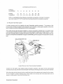
Opi:ional Fuel Filter
INSTALLATION
BOll
A
M~
~"'n'm'
luel filler 01 the water
should be installOO
betvVeen the fuel tank and the
Such e
shown
Is available
from your local Westerbeke representative or your boat builder. This lilter,
for the boatbuilder's use,
comes
with
lor
either hose or metal" ""n,n Mount II
it
in an accessible
and drain off waler accumula"
Hon freouentlv,
Is not i!lstallOO
between the luel tank and the englnemounted fuel system, any water in the
fuel system will lend to inhibl! proper
starts, In addition, partlcies wili pass
on to the 11ft pump's lilter, clogging It
in time,
INSTRUCTTONS
S[frIX£Wlj~filH !R~~
IlttEmBLE
::',cc, .::,_,.
S£CIJREU IG
so PiJsrmm
[RICH DR~lWttG£
II,
Z. IF FUEL is TO BE ~mD mil carPER,
DR 8!Jl;!!H lUBIllS, USE MU1S ~WD fERRULES
p~ntmEO. 8£ SURE IHE lUSING ~RnJm5
1/4 lwei! THROUGH THE HRRULE mHORE
tmmr~~ THE 1M,
], If FUEL IS Hi ~E PIPED iHII! Hos£, iJSE
THE at! l1RR5S BmEO mmss RMD lMSHERS
l,;um.I[!.I. BE mrm HI~l IHE HOSE smcTEO
MRS nip.SfWAL a~Hn mERH~ no CLIhlG Gil THE
BflRB), H!M I1 IS NEOPREkE UNED, ~IW IHM
IT IS MgCG ~PpjHHiEn
4. IF ~ffTER IS PR£5EMT [M INE fUEL, If HLL
COLLECT SLom iU HIE eamJM" OF THE
SEnm:um. lI11t~_ iHE RED fLO~r RIMS
i,
I
\
.... (\
"
FUELFllTER~
\f'----' /,
RE~CI!ES THE DRAiN LlWE ON THE PLAsm
nm, lflDSEN TilE aanOI1 r)IlR!1i PLUG umL
illL mER RUMS OUL
s. nsftHu D"lum PLUG
Eli\1ER
m mm.
mu~m
511 MO AIR eRN
6. EmsIZE m: rUEL PUNP TG mILL IH£
Bm,
Allhough most boatbullders supply a
waler Irap/lilter, some do not
Westerbeke
oilers
a
sOOimenler/waler trap/filler as an op'
lional extra at moderate cost The filter is suppiiOO with littings for either
hose or metal
fuel lines,
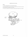
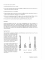
1'1""10,"',,,, Filler Elements
Generator models covered by Ihis
manual have two fuel lilter screens.
filler is
One is in Ihe carburelor
referrOO 10 as the inlet filler ON~''')\
To remove this IlIler screen, unscrew
the filler
and remove Ihe fuel filler
screen behind the plug,
Clean the liller screen or _~"!~"C it with
a new one.
Peri()(jlci,IIV check this filter screen,
REMOVE PlUG
fa [lEAM
lHE InET
FUEL SCREE"
41
Weslerbeke Generalors
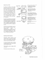
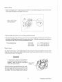
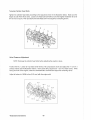
The engine-mounted electric 11ft pump contains
the second fuelliller screen, This pump supplies
fuel to the engine's carburetor
engine
operation, A cleanable filter screen is contained
in the pump's basSo
Remove the base by placing a wrench on the hex
nut and twisting it loose from the bayonet fittings,
Clean the screen as needed, A new base gasket
must be installed each time the pump base is
removed and reinstalled, Ensure a good seal
when replacing the base coveL
Filler Screen
);;;~~ ,f""--+---Magnet
~~J=~~r"-'- __
8aseCover
off the fuel service vaive althe
when servicing the fuel system, Take care in catchany luellhat may
from within the pump when the base Is removed, DO NOT allow
any smoking, open flames, or other sources of lire near Ihe fuel system when servicing, Ensure proper ventilation exists when servicing the fuel system,
Westerbeke Generators
42
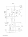
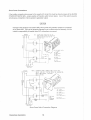
ELECTRiCAL SYSTEM
Engirle 12-Voit DC Control Circllit
The engine that drives the
end has a 12-Voll DC electrical conlrol circuit, as shown on the wiring
diagrams which follow on pages 46 and 47. Reier to Ihese diagrams when troubleshooting or servicing
electrical components on lhe engine.
To avoid damage to Ihe haI1A'V', charging
while the engine is running.
never shut off the engine's battery switch
H()w~)VE", shut off the engine's battery switch to
avoid electrical shorts when working on lhe
engine's electrical circuit with lhe engine stopped.
An overspeed shutdown switch shuts off the generator
set should the engine's speed reach approximately 2175
rpm. This shutdown circuit consumes 25 milliamps (.25
or 1/4th of an Amp) at all times once the generator is connected to its battery. As this only amounts to about 18
Amp-hours in 11
II Is unnecessary to be concerned
wilh this slight discharge during normal seasonal operation. If the generator set were 10 be unattended for many
months, the two easiest ways to stop this slight drain is to
lirst tum 011 the main
switch
12 volts to
the generator set. The second way to stop this slight drain
fuse on the generator-mounted
is to remove the
control
u nMP
ICNTTJ:ON
FUSE
Should the
shutdown Irom an
the
circuit must be reset in order
to restart the
II the
switch ilself is faulty and
it
the STOP switch
will not reset it, lift the T- j coil connection Irom the
switch and connect it
with the T-2
connection on the switch.
NOT connectlhese wires
as loose ends. Make sure that both the
DO NOT
the
with the overT-1 and T-2 terminal wires are connected to the T-2
the
switch only for
purposes.
the overspeed
switch
circuit's intA<1,ritv
switch to maintain this
The minimum recommended
of the M,rr<>,v used in the engine's 12-Volt DC control circuit is 90 125
for the
sets covered
this manual.
"",rrA'V with an external
be sure to disconnect the battery
When qulck-,chaJgio1g
circuit connected while
will
cabies from the hal1",v LA,Bv.no the
rl'"n~r''' the alternator's diodes.
Westerbeke Generators
Altemator
When testing the alternator circuit
circuit), do not use a high-voltage tester such as
a megger; damaged diodes could result When operating the
do not disconnect
the
terminal of the battery from the
!erminal of the
nor disconnect the
terminal of Ihe battery from the
When dO,Qni""
eralor with a sleam cleaner, be carelll! to
steam away from the alternator,
The charging
consists 01 an alternator with an intemai voltage regulator, an pn"inA-rnn,
breaker, and a
and
wires. Because of the llse of
voitage regulator is very
and is built into the rear bracket 01 the aiternator.
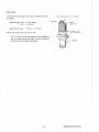
Charging Vol!age Tesl
If you suspect that the alternator is not producing enough voltage to charge the engine's battery, perform
the following voltage test
A
R-
R
A
Interconnections for Charging
1. Using a
connect the voltmeter's red wire
Reier to the schematic shown above.
to the
Test
terminal on the altemetor.
toa
3. Start the oenel'a!()Cand record the reading
by the voltmeter.
The voltage
lor a properly operating alternator should be between 13.5 to 14.5 voits. If your alternator Is over or under charging, have it replaced or rebuilt by a reliable service shop. Before
the
or replaoement, ensure that 12-Volls excitation is
altne EXC connection with
alternator for
the ON switch depressed, should the above test show
voltage at the
terminal. The
EXC connection must have 12-Volts
while the ON switch is depressed, since this constitutes excitation
for the alternator's
Weslerbeke Generators
r~EMOTE
IN~,TRU)\IENT PANEL
(REAR VIEW)
I
I
REO!W/PURPLE STRIP'E~~~~~
i--
I
I
I
l8~ []
l')I(W8T
'lKW Be
~12REDj\
m/w
PURPL~_
STRIPE-~
EO!W/PUR
3!.\MP STLt.~'li
:; lIHP RUN
t:i
TO T82
TO n-2+-
I. 14 PURFLE
\
2t,HP -"" .. ~
T1",1
-e
fj-
T1-2
/
co
T4-4
-e
1
::e
';"
iT
'"
'"o"'"
'"
::I
<0
-
01
'"
iil
TO 1'81
TO
Ij
TO
-M---
e
TO T
~fl.MP
1_1<1_~.?£UR/\{!REO
srRk[
TOTI-21
T4-5
BLACK
1-'t2YELfW/RED
-
__
SI
m
+
Z
""16 BLACK
~
c
"'16 BLACK
:i
"
m
,
J-~-.-+----h~
n·1
/
!:
'"-"
IT
Q
m
~>
.;
z
~
W
zm
r
::e
* 16 TAN
""16 BLAC e
l~!:J'1P ST~_I.J.tlS._"
6 AHP RUNNING
12AMP STARTIN_q,_ ..
'"
ii
T3-2
l-_-~J~---i
z
'
o
HOURS
c
VOLTS
~
i!:;:
L~_ _ _ _ "I~.PURPLE
~
STRIPE
I
L ___ _
5
r
I
TO T8
,
...•".-
!:
cO
y.
0
-,
m
4 TAN
m
o
E
tI-\GLT..BL
1
TO T 2 .. 4 -<!-~.---f---l
WATER TEHP.
OIL PRESSURE
/vi/PUff
ON
STllIP[
PlQ_STRiPE
~ lG PURPL
fj
~
TO T (-]
12 RED
::l:l
--::::J~
'16 PURPl
-e
"(E:
_ ~12 REDf~ PUR SlTilPE
~---
I
I " 14LTbLUE ----f3T'1'6f
TOT2<)~
I"
az
~
,-
"J2
,/ 8e
TO T83-2
~
'
±
,J
STtd~'
STOP
TO T81- 2
o
1
G~~-:::-"1
"-12 Y ,)WiBI9J.:?lR1Pf_ I
8.SKW BT
!2.5KW 8T
SEE DWG
=~'c' 11 Eg
'f:s'-
1
I
I
--
,
----~~----
--~~------~----------------------~~
'II:
w
III
'"""
DC WIRING DIAGRAM #31190
1 012
:€t
<::C:::fc
"'1~
;
BROWN
. " OH"G8
ALTERNA.TOR
e
~
SPARK
CIRCUIT
#14 PURPLE
PLUGS
8REAKER
~
OIL
BAnERY
i'7-!Iir3'
~I
~
~
I
GROUND
ro aWCK
:
PRES~~
SWITCH
~~~~~
,
~
1~
~
i-=!
oenONAL
STARTER
-'"
r:!:
=:_~C.C -- ~
t,j~
:TEMP.
:_SENDER
'~
WATER
: !~7;CH
~C~'
~;;:!~ST
CROKE
~
'W~~~;- ~
!J../
L~
j
~~
!;~~~R6-:
t
/
1/ 14 R<"tl!Pl
.F
.~
",p, "
FUEL
PUMP
"mCR
I; ~ !
~
!
i?<
- I~
Q
~
#1.< RED/PURPLE
!
CJ
","Lee,
1\1 !
I!n'}! i ~!I
i8·:>
TB-2-
PANt~S
DAAWlNG 307()5
""LK
~
SEt
-
r. ~
,
=_J
i
---c
,
'
,
"""'"
''''
!
,
,
•
I
C-J
! ,*12' ~URED' ~
*14 YELJRSC
I
Hii'
---
'"
I
FUSE 2
15 AMP S
HOURM ETER
E
'''''''''''' '"M'"
STOP
SWITCH
,
' " BLK
;;;::v
FOE CO"lNECTtON TO
REMOTE
d i~
§
~
~
SWITCH
FUSE 1
e AMP
,
;
' " POHPCE
..r"
START
,
i TB_1
\1
,
""
OVBRSPEEC:~
CiRCUIT
t
_~
f,i
'~:;'E~
' " REG
i
Weslerbeke Generalors
'" RED
'"
HEC
i
46
0'
SWiTCH
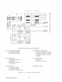
DC WIRING DIAGRAM #37190
2012
e
e
12 VOLTS DC
: 'I' hMER. SW.
:"-fJ SEE NOTE 3
START SOL
STARTER
II
_
~t---------~ -----i@---~
_ ___-I
e-,
c.s.
L
I
CUT r::::\ALTERNArOR
,
·-~R~E~G~
~,G
~
("
T83-4
.iAC
± I
I'd:
l2.j
-----=:~-.-.--<
T82-1
TB2-2
[J-----"'
:'0
,,
~
"----
NOTES,
1, WESTERBEKE GASOLINE MARINE GENERATORS AS SHIPPED FROM THE FACTORY AND EXCLUSIVE OF OPTIONAL REMOTE INSTRUMENT OR CONTROL PANELS COMPLY WITH U.S.
COAST GUARD 33CFR·183. ACCESSORY INSTRUMENT AND CONTROL PANELS 00 NOT
NECESSARlLY SO COMPLY AND ARE a-HENDED TO BE INSTALLED ABOVE THE DECK AND
ISOLATED FROM GASOLINE SOURCES IN ACCORDANCE WITH 33CFR-183.41O{B}.
IT is THE RESPONSIBIliTY OF THE BOAT MANUFACTURER TO ENSURE THAT THE INSTALLA_
TION OF THESE GENERATORS, AND OPTIONALLY THEIR REMOTE INSTRUMENT PANELS,
COMPLY WITH 33CFR-183.
2. THIS PRODUCT IS PROTECTED BY A MANUAL RESET CIRCUlT BREAKER LOCATED NEAR THE
STARTER AND AS CLOSE AS POSSIBLE TO THE SOURCE OF CURRENT. EXCESSIVE DRAIN
ANYWHERE iN THE INSTRUMENT PANEL, WIRtNG OR ENGINE WilL CAUSE THE BREAKER TO
TRIP. IN THIS EVENT, THE ENG!NE WilL SHUT DOWN BECAUSE THE OPEN BREAKER WILL
DISCONNECT THE FUEL SUPPLY. THEREFORE, THE BUILDER/OWNER MUST BE SURE THAT
THE INSTRUMENT PANEL, WIRING AND ENGINE ARE INSTALLED TO PREVENT CONTACT BE_
TWEEN ELECTRICAL DEVICES AND SEA WATER.
3. AN ON-OFF SWITCH MUST BE INSTALLED TO DiSCONNECT THE STARTER FROM THE BAT_
TERY IN AN EMERGENCY AND WHEN LEAVING THE BOAT. TWELVE VOLT STARTERS TIPI_
CAllY DRAW 200 TO 300 AMPS WHEN CRANKING. THE DURATION OF iNOfVIDUAL CRANKING
CYCLES SHOULD NOT EXCEED 30 SECONDS. A SWITCH WITH A CONTINUOUS RATING OF
175 AMPS AT 12 VOLTS WilL NORMALLY SERVE THIS FUNCTION, BUT A SWITCH MUST NOT
BE USED TO MAKE THE CiRCUIT,
4. SENDERS ARE SUPPLIED WITH AN OPTIONAL iNSTRUMENT PANEL
47
Weslerbeke Generators
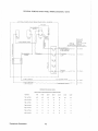
OPTIONAL REMOTE START PANEL Wlli'IIN'G DIAGRAM # 3!l10!l
r - -- --OPTIONAl.
-->- -
Rt:MOTE 5TA.RT PANEL(RlAR V!lW)
PN.33703
- - - - - - - - ------------1
- --'-:---
~~-:
!
,
!
'"12 Y[L/wiREO
n
Ir~
:
STR'Pe
1
~
I'
(
:
L~
:
~r~t-,. oi~
L-.....J '-.
STAR"'"
I
'
,,[rl
I!
~'---#?~
<;"
STOP
I
ON
:
12RlD
:
! o
".'"
'::::
<f12REO/W/PUR STRIPE
STRIPEI',
~
I
:
t;;
I
:
=-03:
- Q:
W
Q.
iJJ
?
STRIPE
II
;;,
,
T3-1
o
::
#"1£, PURPLE
:4.: i 2
T4-3
T4~~
\
:
ii
!
I
,,
!i!i
II
~14BLACK ~TO 12-5
"2 {.\MP
!
9 A,"P STARTiNGo _ _ _ _ __
-- .--.---,-
1<!2RED/WIPURSTR~E
b ANP nUNNING
'_'I',' TO TB3~G
11
, TO
~ TO
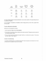
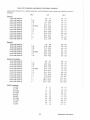
MINIMUM WIRE GAUGES (AWG)
WIRE LENGTH FROM GENERATOR TO REMOTE PANEL
Termlnals
0.-16'
16-20'
20-25'
25-32'
32-40'
40-50'
50-65'
TSH to TS3·'!
#12
#iO
#10
#8
#8
#6
#6
TBi-2 to T83-2
14
12
12
10
10
6
T82-1 to TB4-i
14
14
12
10
10
8
,
,
TB2·2 to T84-2
14
"
14
14
14
14
14
TB2-3 to TB4-3
14
14
14
14
14
14
14
TB2-4 to T84-4
14
14
14
14
14
14
14
TB2-S to TB4-3
14
14
14
14
14
14
14
4<1
II
:1
L-~----t-i~A~P~:R~:------------·---:':YEL.wHEDSTRIPE
Westerbeke Generators
TO T8 '}--2
TO T2-2
AMP
_,
I
TO T2-1
lSAMP STARTING
6 AMP RUNNING
!
I'::'
;1 II:'~
,
,,
SEE
~"i2 REO/W!PURPLE
+I--t-<§l
!15KW BT
SEE DWG 37190
9 KW 8T
",D:2W"G".3"5"4,,3,,9'iJ-S,,,E,,,E~."0"",,G,,.3,,5,,3,,9,,7_
4 KW Be
5.5 KIA Be
I
\
L'-";:.bi:PU""R;:P"L-"E_ _ _ _ i
8.5 K:''; 8T
i25 K\-j BT
I
"'T4.0/'
"'\2 YEl./w/RED
I
IvY/PURI !
H2
TI-[
Ii
TC T633
II, TO
TBi·!
COOUNG SYSTEM
Westerbeke marine gasoline engines are designed and equipped for fresh water cooling. Heat produced in
the engine by combustion and friction is transferred to the fresh waler which circulates throughout the engine. This circulating fresh watsr cools the engine block and its internal moving parts. The heat is transferred
externally from the Iresh water to sea water by means of a heat exchanger. similar in function to an automotive radiator. Sea water flows through the tubes 01 the heat exchanger While fresh water flows around the
tubes; engine heat transferred to fresh water is conducted through the lube walls to the sea water which is
pumped into the exhaust system and discharged overboard. In basic terms, the engine is cooled by fresh
water, the fresh water is cooled by sea water, and the sea water carries the transferred heat over the side
through the exhaust system. The fresh water and sea water circuits are independent of each other. Using
only fresh water within lhe engine allows lhe cooiing water passages to stay clean and free from harmful
deposits. The two independent circuits and their components are discussed in the following paragraphs.
Fresh Waler Circuit
NOTE: Refer to paragraphs A and B in this section on the recommended antifreeze and water
mixture to be used as the fresh water coolant, and for information on filling the fresh water sys-
tem.
Fresh water is pumped through the engine by a belt-driven circulating pump, absorbing heat from the engine. The fresh water coolant circulates through the engine's block absorbing heat, then passes through the
thermostat into the exhaust manifold, then to the heat exchanger where it is cooled, and then is returned to
the engine block through the suction side of the fresh water circulating pump. When the engine is started
cold, external fresh water flow is prevented by the closed thermostat (although some fresh water flow is
bypassed around the thermostat to prevent the exhaust manifold from overheating). As the engine warms
up, the thermostat gradually opens, allowing the engine's fresh water coolant to flow unrestricted to the external portion of the cooling system.
A. Fresh Water Coolant (Antifreeze) Mixture.
It is recommended that a freshwater and antifreeze mixture be used year-round. Water, when it freezes, expands sufficiently 10 split the heat exchanger and crack the engine block. A waler/anti!reeze mixture of proper
concentration will prevent freezing (see pege 50 for an antifreeze/water mixture chart).
Use soft water with few impurities, such as tap water (potable water) or rainwater. Never use hard or foul
water. Use of hard water or waler containing Impurities will lead to the collection of scale in the engine and
heat exchanger which will reduce the cooling system's efficiency.
Antifreeze 01 poor quality or without rust inhibitors will cause corrosion within the cooling system. Always
use antUreeze which is compatible with aluminum cooling system components and which is made by a reliable manufacturer. Never mix different brands 01 antifreeze.
Make sure that the cooling system of the engine is well cleaned before adding antifreeze.
Recommended antifreeze lor year round use is ZEREX or PRESTONE with rust inhibitors.
In order to control the concentration 01 the mixture, mix the antifreeze and fresh water thoroughly before adding it to Ihe cooling system.
Westerbeke Generators
ANTIFREEZE ADDITION DATA
Antifreeze
Concentration
Freezing
Temperature
13
OF
(' C)
23
(-5)
23
30
35
45
14
5
-4
-22
(-10) (-15) (-20) (-30)
50
-40
(-40)
-58
(-58)
NOTE: It is advisable that the antifreeze concentration be selected on the basis 01 a temperature which is about 10° F (5° C) lower than the actual atmospheric temperature expected,
S, Filling the Fresh Water System
A coolant recovery tank kit is supplied with each Westerbeke gasoline generator, The purpose 01 this
recovery tank is to allow lor engine coolant expansion and contraction, during engine operation, without the
loss of coolant and without introducing air into the cooling system,
This coolant recovery tank should be installed at, or above, the engine's manifold level, in a location where
it can be easily monitored and where coolant can be easily added if needed (see the figure below), A stainless steel mounting bracket is supplied with each kit along with a 3D-inch length of clear plastic hose and
clamps to connectthe hose between the engine's manifold fitting to Ihe hose spud on the base olthe recovery
tank,
Coolanl Re<;overy
Recommended Installation
Cooiant from Ihe engine, when healed during lhe "nninA'~ nl'\'''Alinn will expand, lifllhe sp,rln!J-i()acled
manifold pressure cap, and enter the recoverytanl<via the hose cOlnm'.ctiinnthe
the manifold,
a small check valve In the pressure cap is
the contracWhen the FlnCllnA is shut down and
tion of the
some of the coolant in the recovery lank to be drawn back into the
engine's
Iree of air and without loss.
Weslerbeke Generators
Fililhe fresh water
~v"t'''Tl
as follows:
1. Remove the pressure cap from the manifold,
2, Pour a clean, fresh waler coolant mixture into the manifold and allow enough time for the coolant to fill the
fresh water cooling system and expel all aiL
3, Replace the pressure cap on the manifold,
4, Remove the plastic cap from the coolant recovery tank and fill the lank with coolant halfway between the
ADD mark and the MAX mark Replace Ihe cap on the
man~old,
5, Start and run the engine long enough for the engine to warm up so that the thermostat will open, allowing
the coolant to flow through the engine block and to the rest of the fresh water cooling system,
6,
Add coolant to the recovery tank, as required, to top off the fresh water cooling system,
Thermostat
Generally, thermostats are of two types, One is simply a choking device which opens and closes as the
engine's temperature rises and falls, The second type has a bypass mechanism, Usually this is a disc on
the bottom of the thermostat which moves downward to close off an internal bypass passage within the head,
Since 1980, each type 01 thermostat has a hole punched through it The hole is a bypass to prevent the exhaust manifold from overheating during the engine's warm-up, Replacement thermostats must have this
design characteristic.
Sea Waler Circuit
The sea waler flow is created by a belt-driven, positive displacement, neoprene impeller pump, The pump
draws sea water directly from the ocean
through the sea cock and sea water strainer
and passes the water to the heal
exchanger's sea water inlet The sea water
passes through Ihe heat exchanger's tubes,
from which heat from the fresh water system
is absorbed and then Is discharged from the
cooling system overboard through the
water -injected wet exhaust system,
A zinc anode, or pencil, is located in the sea
water cooling circuit within the heat exchangeL The purpose of the zinc anode is
to sacrifice itself 10 electrolysis action taking
place in the sea water cooling circuit, thereby reducing the effects of electrolysis on
other components 01 the system The condition of the zinc anode should be checked
monthly and the anode cleaned or replaced,
as required, Spare anodes should be carried on board,
Ii Ell
ANODE
REPLACE
REPLACE
CLEAH
OR
REPLACE
Zinc Anode Conditions
51
Wes!erbeke Generators
Sea Water
The sea water pump is a
bell-driven
pump with a non-ferrous
impelier. The impeller has flexible vanes which wipe against a curved cam
within the im""I1,,, lU'U",IlU.
producing the pumping action. On no account should this pump be run dry. There should always be a
spare impeller and impeller cover gasket on board (an impeller kil).
Alternator (DC) and Water Pump Drive Belt Tension
Never attempt to adjust the drive belt's tension while the engine is in operation.
CAUTION
Excessive alternator and water pump drive belt tension can cause rapid wear of the belt and
reduce the service life of the fresh water pump and alternator shaft bearings. Excessive slack
or the presence of oil on the belt can cause bell slipping, resulting in high operating temperatures, as well as insufficient alternator output.
The alternator and water pump drive belt is properly adjusted if the belt can be deflected no less than 3/8
inch and no more than 1/2 inch (10 mm, 12 mm) as the belt is depressed with the thumb at the midpoint between the two pulleys on the longest span of the belt. (See the figure below.) A spare drive belt should be
carried on board.
Alternator and Water
Westerbeke Generators
52
Belt Tension
Illustrated below is 11
Both fresh water and sea water How
''''ou,,'' thek in(je!:>ermlsn! ron!!"" circui!s< Please refer 10 the Parts List for individual
numbers and
ti,,,,crin!k1l1R for your sp"dfic CI(1niil1(1 syritmR
\;iAH~
IMJHTlEO
EUH)W'
HHIHlST
MAlIiHGU}
CGOlfHH
RECOVERY
TfHiOC
HEAT
(UMTlHJLlER
FRESH WRIER PUMP
53
Westerbeke Generators
LUBRiCATION SYSTEM
Ene,i"" Oil
For the engine's lubrication, llse a lubricating oil designated jor gasoiine service. Use a good grade of oil
having an API specification 01 SO or
preferably SE. DO NOT use oils designated DS.
Oil Vis'co1sitjl
Use oil having a viscosity best suited to the atmospheric temperature. Rejer to the oil viscosity chart below.
(C )
10
- 30
40
20
50
Temperature
IF I
o
40
20
60
80
100
120
Engine oil
Oil Pressure
The engine's oil pressure is indicated by the oil pressure gauge (when equipped with one) or is monitored
the standard oil pressure switch.
During normal oD·eration, the engine's oil pressure will range between 35 and 55 psi (engine hot).
NOTE: A newly
cold
can have an oil pressure mo.r/in,n "nworrl:o of 60 to 80 psi.
as low as 35
These
may also
A warmed engine can have an oil pressure
vary depending upon the load that Is
on the gener·alc}r.
Your
set is lilted with an oii pressure
switch as standard
Should your onn'no'o
oil pressure
below a safe operating pressure, the sensor will shut the onn',"o OFF to
any internal damage to your
from
the DC
to the Inc,(tlcm
54
include
1. Draining the 011
Discharge the old oil through the sump drain hose (attached althe
Iron! of the engine) while the
is still warm. Drain the old oil
completely, replace the hose in its bracket, and replace the end
cap securely.
Always observe the old oil as il is removed. A yellow/gray emul·
sion indicates the presence of water in the oil. Although this con ..
dilion is rare, it does require prompt attention to
serious
damage. Call a competent mechanic should water be present in
the oil. Sea water present in the oil can be the result of a fault in
the exhaust system attached to the engine, and/or water siphoning
through the sea water cooling circuit into the exhaust, filling it up
into the engine (refer to the exhaust illustrations on pages 27 and
29).
2. Replacement of Ihe Oil Filter
When removing the used oil filter, you may lind it helpful and cleaner
to punch a hole in the upper and lower portion of the old filter to
drain the oillrom it into a container before removing it. This helps
to lessen spillage. A small style automotive filter wrench should be
helpful in removing the old oil filter. Place some paper towels and
a plastic bag around the filter when unscrewing it to catch any oil
left in the lilter. (Oil or any other fluid on the engine reduces the
engine's cooling ability. Please keep your generator's engine
eiean.) Inspect the old oil filter as it is removed to make sure that
the rubber sealing gasket came all with the old oil filter. If Ihis rubgently remove it. The replaceable cartridge-type
ber sealing gasket remains sealed against the
oillilter requires no
so it may be
disposed of.
When installing the new oil fiite. element, wipe the liiter gasket's sealing surface on the engine block free of
oli and apply a thin coat of clean engine oii to the rubber gasket on the oil filter. Screw the filter onto the
threaded oil filler stub, and then tighten the filter
by hand
NOTE: Generic filters are not recommended, as the material standards or diameters 01 im ..
portant items on generic parts might be entirely different from genuine parts. Immediately after
an oillilter change and oil 1111, run the engine to ensure that the oil pressure is normal and lhat
there are no oil leaks around the new oilillter.
3. Filling the Oil Sump
Add fresh on through the oil filler cap on the valve cover. After refilling the oil, run the engine for a few moments while checking the engine's oil pressure. Ensure there is no leakage around the new oil filter or from
the oil drain system, and then stop the
Then check the quantity 01 oil with the dipstick. Fill to, but
mark on the dipstick, should the engine require additional oil.
not over, lhe
Weslerbeke Generators
BT GENERATOR
This
is a brushless self-excited
which
lorce 01 the Anrlln" to
produce AC
The copper and laminated iron in the exciter stator are ""<nnndhl,, lor the selii-e)(citing
The
field
causes an AC volta{J8 to be Induced into the related
leature of this
exciter rotor windings
rolationo Diodes located In the exciter rotor
this
DC and suppof the
lieldo This creates all
field which rotales
the
ly it to the
windings of the main stator o
an AC
which is
to a loado A transformer is connected
in
to the AC
of the main statoL An AC
is
in the
of the
transformer and main stator and
in tum,
10 a fuil-wave
rectifier, The rectifier
a
DC
to further eXCITe the exciter stator
10
a rated AC output
An optional soUd-slate voltage
is available to work in tandem with the transformer
produce a more stable AC output (see the top of page
10
No-load Voltage Adjustment
A voltage adjustment is made with the compound transformer governing generator
"'!JWdUU'
1 The selector switch must be in the COMP positicno
0
20 Operate the generator and
a moderate load momentarily; then remove the loado Note the voltage
The no-load vOlta£16 should be befrom the generator's 120-Volt leg(s) (110 Volls at 50
tween 121 - 123 Volls at 61,5 - 62 Hertz (111 - 113 Volts at 51,5 - 52
NOTE: The No-Load voltage should be adjusted to the voltage produced
when: the generator is started, a
load is applied to excite the lransforl1neL and
then removed The voltage produced
the
alter this
load is removed
Is the no-load voltage,
0
30 To raise or lower lhe voltage, non-conductive shims of varying thickness are inselted or removed from
under the laminated steel bar thai is situated on top ollhe compound transformer The material used lor
shimming should not sofien at temperatures in the 176 F (80' C) rangeo A small reduction in the no-load
voltage (1 to 3 Volts) sometimes can be accomplished by gently tapping the
of the laminated steel
bar to reduce the air gap between the existing shims and the transformer coreo
0
See the next page lor an illustration of the generator's AC distribution bOK
Weslerbeke Generators
56
Optional AVR
VOlIR,l RDJUSTMENT
SHIM [GeAllON
l AMlMAHO Sl[n
BRR
GreenM'hile
~~~~\~ \
1(-\\\\
\
COMPOUND
TRRNSfORMER
!
Generator AC Distribution Box
BTG 12.SKW and BTG 15.0KW
Under no circumstances attempt to increase the no-load voltage by increasing the gap between the laminated steel bar and the transformer core without the llse 01 shims. Magnetic
forces created within the transformer
the generator's operation may close the air gap
and reduce the no-load voltage output.
4. To remove the laminated steel bar, remove the two upper securing bolls from the compound transformer
and lift the barlrom the transformer. The add~ion 01 shim thickness will raise the no-load voltage and,
conversely, the removal 01 shim thickness will lower the no-load voltage.
Varying shim thickness by .001 inch (0.025 mm) will change the no-load voltage by 4 to 6 Volts. (Shim
material should be non-conductive; that is, tt should be transparent or colored stationary store materiaL)
51
Westerbeke Generators
UH'{HHHE!1
STEEl BAR
SElECTOR
SWITCH
r;~~~~~~f~F<f) EXIT
GUT PUTHOLE
LEAD
;{
(GROMMEll
BRIDGE
VOL TAG[
RECllFI
TEIHIOMETER
(fINE ADJUST)
REGULRTOR
PLUG
IlLUSTRAllON SHOWS TERMIRRLS
CONNEClEO fOR 1201240 VOLT
I'
I
60 HERTZ ON COMPOUND
TRnNSFORMER REGULATION
Generator AC Distribution 80)(
BTG 8.5KW
Under no circumstances attempt to increase the no-load voltage
increasing the gap between the laminated sleel bar and the lransformer core without the use of shims. Magnetic
forces created within the translormer during the generator's operation may close the air gap
and reduce the no-load voltage output.
4. To remove the laminated steel ber. remove the two upper securing bolls from the compound transformer
and lift the bar from the transformer. The addition 01 shim thickness will raise the no-load voltage and,
conversely, the removal of shim lhickness will lower the no-load vollage.
Varying shim thickness by .001 inch (0.025 mm) will change lhe nO-load voltage by 4 10 6 Volts. (Shim
male rial should be non-conductive; thai is, il should be transparent or colored
store material.)
Weslerbeke Generaiors
58
eGa':
*
F--------
+:
11
1 +
I
L
2
_______________
I
Ji
AC
"
T
7
E
5
R
M
I
N
3
!
I-
:
I
"2
----,
"B
:5
A
l
I
______
I
J
B
l
0
RED
C
K
F
®
A.V.f?
BL.UE
S
T
BLUE
U
0
G
+~
Fz ,"'-
--
>
liB!l;E'N
_l:~J-ycc"w
I
\
'-~: I
\ ..;
BLACK
BLACK
.
>.v.R.~
BTG 12.5KW and BTG 15.0KW Generetors' Internal Wiring Diagram
A. EXCiTER STATOR WINDINGS
D. COMPOUND TRANSFORMER
1. Compound Transformer Windings
2. Compound Transformer Windings
3. Compound Transformer Auxiliary
Windings
1. Exciter Stator Windings
2. Exciter Stator Windings
B. EXCITER ROTOR
1. Auxiliary Windings (a - b - c)
2. Diodes (6)
3. Rotating Fieid Vvindings
4. Pozi Resistor
F. SELECTOR SWITCH
1. Compound
2. Electronic and Compound
C. MAIN STATOR
1. Main Stator Windings
2. Main Stator Windings
3. Main Stator Auxiliary Windings
G. BRIDGE RECTIFIER
(Optional AVA. - Automatic Voltage Regulator)
59
Weslerbeke Generators
- 1 - - - - - 10
WHITE
B
L
0
C
K
Fl
WHITE
®
$
T
U
a
AED& WH!TE
I---$--
+
~~---4~r-~~4-~
GREEN
;
G
WI-HiE
+
YELLOW & WHiTt
~.----~~~~--~
BLACK & WHilE
-
A VR
. .
PLUG
.
BTG 8.5KW Generator's Internal
A. EXCITER STATOR WINDINGS
1. Exciter Stalor Willdi!ll1~
2. Exciter Stator Willrlilln~
D. COMPOUND TRANSFORMER
1. Comr10Lind Transformer Whvih",.
2.
3.
Transformer Wh,riil'(1R
Transformer f,"'"lli',n,
B. EXCiTER ROTOR
1. f'oU>CllId< Wh,rlil",~ (a b . c)
2. Diodes (6)
3.
Field Wio,rli,'''4
4. Pozi Resistor
F. SElcEC:TCIR SWITCH
1. COfflpOUi.,d
2. Electric and CClmrlOIJrld
C. MAIN STATOR
G. BRIDGE RECTIFIER
1. Main Stator
2. Main Slalor Willriirl(l~
3. Mein Stator t\UJZ!Hidr y Willditl1'11
(Olllic,nai A. V. R. . Automatic Voltao'e nbldl'f<"U'
Weslerbeke Gei1erelor!l
An rm,tinn~1 solid-state vollagi8
Is available lor use with the BT series generators.
When 1I181alled, and the "'Ituume)" SWITch Is moved to the ELEC
the regulator works together with
the standard
transformer
tc
the generator's voltage output In the ELEC mode,
the
prc)vicies excitation to the group 1 exciter windings, and the transformer provides excitation to
the group 2 exciter wil'lriinns
In5111 Ilation
I. The reglulaltor is mounted
existing tapped holes in Ihe generator's case. Use two (2) M4
screws, each 15 mm
with lock washers to mount the regulator board.
x 0.7-mm
2. Connect lhe 5-prong generator plug to the receptacle on the regulator board.
NOTE: The plug is keyed to engage the regulator receptacle in one direction. Check this and
insert it correctly.
3. Before moving the selector switch to the ELEO position, make
sure lhat the no-load voltage is adjusted to 115 volts with the
seledor swttch in the COMP posiiion. Follow the procedures
for the "No-Load Voltage Adjustment," page 55.
4. With the generator's no·load voltage now set at 115 volts,
move the selector switch into the ElEC position. Adjust the
regulator board's potentiometer to set the no-load voltage a\
120
51.5 - 62 Hertz (110 Volts, 51.5 - 52 Hertz), The generator's
output should be within ± 5 percent from 110load to lull-load.
Generator
"'-"J'",'-'v is a direct result of An,~inAIr1A'lAr"tf" spe,ed:
1800 RPM - 60 Hertz
1500 RPM, 50 Hertz
To
the
"A'nA1~t(;r'" HtiUU'"
reler to Ihe "MAINTENANCE AND ADJUSTMENTS" section of this
manu,,!. page 74.
the voltage, current and frequency rating of the generator. An AC wiring
The generator's data
decal is affixed to the inside of Ihe louvered cover 0111h8 generator end. A diagram of lhe various AC voltage connections is
on the decal. The information on Ihe decal is similar to the figure shewn on lhe
following page.
The
is a
reconneclable 120 Volts AC two-wire or 120/240 Volts AC three-wire, a! 60
or '110 Volls AC tlN<)-\!\'ire 110/220 Volts AC three-wire, or 220 Volts AC two-wire, at 50 Hertz. Refer 10
Weslerbeke Generators
the "SYSTEM SPEC:IFICPITI()NS" section of this manual for nnnAl"8ir)C
page 19 for the BTG 1
and pege 23 for the BTG 15"OKW
"l!inln~
page 15 lor the BTG
NOTE: We recommend that the instailer
AC amp-meters (optional) so tha! the
operator can observe the load being taken off each leg of the generator
A circuit breaker should beins!alled between the generator and the AC load" This circuit breaker should be
rated at 120% of the generator's AC
and be able to react
to
subject to motor starting considerations"
120V 60Hz
1201240V 60Hz
-02
5 Ii"';
7h
06
7
'0
Oa
03
SO
03
I
L1
llBV 50Hz
II ,I
sO
"""6
7"'"
(
6.0
3
~
"'"
89
I
N
L1
110/220V 50Hz
02
-Ill
••
220V 50Hz
sO
sO
II
I
AC Voltage Connections (6 Stud Terminal Block)
(Used with the BTG 125KW and BTG 15"OKW Generator
NOTE: The frame ground wire must be moved when changing from 110 Volts, 50 Hertz to
220 Volts, 50 Hertz"
For making connections to the AC terminal block, use 1/4 inch terminal ends Ihat will accept multi-strand
wire sized for Ihe number of conductors in Ihe bundle, the rating of the conductor's insulation, and amperage
that will be drawn through the conduc!or(s)" (ReIer to the generator's dala plate lor generator amperage
ratings,,)
Weslerbeke Generators
62
Refer to Ihe "SYSTEM SPECIFICATIONS" section of this manual for rll'\'A'Pttnr ratings, page 15 for the BTG
6,::l!,"V, page 1910rthe BTG 1
and page 23 lor the BTG 15,OKW,
NOTE: We recommend thatthe installer provide AC amp-meters (optional) so thatthe operator
can observe the load being taken off each leg 01 the generator,
A Circuit breaker should be inslalied between the generator and lhe AC load, This circuit breaker should be
rated at 120% 01 the generator's AC output and be able to react quickly to overloads, subject to motor startconsiderations,
120V 60Hz
0
()
1201240V 60Hz
To FRAME
()
'ilh
TOF RAME
I
0
I
0
0
0
0
0
J==J Ll
N c:::::::j
0
~ )
Cl
[0
0
I==l
(OJ
0
0
0
0
n:
U
N
L
HOf22'OV 50Hz
=
0
0
0
0
c
CL
0
w
° ~I;:M
N
°
220V 50Hz
110V 50Hz
=
o
0
0
=
0
0
0
0
=
p,o
l'n
0
0
-0
a
w
"""''-' <:::
-0
'n
U
U
N
L,
AC Voltage Connections (12 Stud Terminal Block)
(Used only with the BTG 8,5KW Generator Set)
NOTE: Thelrame ground wire must be moved when changing from 110 Volts, 50 Hertz to /220
Voits, 50 Hertz,
For making connections to the AC terminal block, use terminal ends for #10 studs which will accept multistrand wire sized lor the number of conductors in the bundle, the rating of the conductor's Insulation, and
amperage that will be drawn through the conduclor(s), (Refer to ihe generator's data plate for the generator's amperage and voltage ratings,)
63
Weslerbeke Generators
Shore Power Conneclione
If the installer connects shore power to the vessel's AC
Ihls must be done
means of the SHORE
center
transfer switch shown belcw. Use 01 lhis switch
simultaneous connection 01 shore power to ""'01"·";'" UUIIJUL
Damage 10 the "A"AI''';'·'' can result if
shore power and nAn'H'~"V
are connected
at the same time. This
01
is nol covered under the WRre"",!')· it Is lhe
installer's
to ensure that all AC connections are correct
SHIP-lO-SHDRr $W1HIl
(l
POLU
NOTE: DIAGRAM SHOWS CONNECTIONS FOR R TWOWIRE,
120-'VGLY SYSTEM FROM THE GENERATOR,
WITH THREE-WIRE, 1
'j;'""a
f'N:
HKf'S/FOf E)
("\1
32~Hir9
Ff.!
~'KPS/POLt;)
(80
Ship'~
Load
Note
N;)2·iONoo
equiprrn:lf)\
Shore Power Switch Connection
Weslerbeke Generators
(125
pp,
HHP5/POLF)
32133
(20"
AHf-'S/PDtT)
GENERAL INFORMATION AND CARE OF THE GENERATOR
Use of Electric Motors
The power required to start an electric motor is considerably more than is required to keep it running after it
is started. Some motors require much more current to start than others. Split-phase (AC) motors require
more current to start. under similar circumstances, than otherlypes. They are commonly used on easy-starting loads, such as washing
or where loads are applied after the motor is started, such as small
power tools. Because Ihey require 510 7 limes as much current 10 start as to run, their use should be avoided,
whenever possible, if the electric motor is to be driven by a small generator. Capacitor and repulsion-induction motors require from 2 to 4 times as much current to slart as 10 run. The curren! required 10 start any
molor varies with the load connected to it. An eleclric motor connected to an air compressor, for example,
will require more current than a motor to which no load is connected.
In general, the curren! required to start I 15-Volt motors connected to medium starting loads will be approximately as follows:
MOTOR
SIZE
(HP)
AMPS FOR
RUNNING
(Amperes)
1/6
1/4
1/3
1/2
3/4
1
3.2
4.6
5.2
7.2
10.2
13
AMPS FOR
STARTING
(Amperes)
6.4 to 22.4·
9.2 to 32.2*
10.4 to 72.8*
14.4 to 29.2
20.4 to 40.8
26 to 52
* Note that in the above leble the maximum "Amps for Starting" is more for some small motors
than for larger ones. The reason for this is that the hardest starting types (split-phase) are not
made in larger sizes.
Because the heavy surge of current needed for starting motors is required for only an instant, the generator
will not be damaged if it cen bring the motor up to speed in a few seconds. If difficulty is experienced in starting motors, tum off all other electrical loads and, IT possible, reduce the load 011 the electric motor.
Required Operating Speed
Although individual units may vary slightly, the normal voltage and frequency of lypicaI60-(50-)Hertz enginedriven generators described in this manual are approximately as follows: run first with no load applied, then
at half the
capacity, and finally loaded to its full capacity as indicated on the generator's data
piate.
See the rpm/Hertz/frequency chart on the next page.
Weslerbeke Generators
Generator
120V (1
Plants
4-Pole
Load
(rpm)
240V
Plants
None
1830
(1530)
62
(52)
122
(112)
240
(224)
Hall
1800
(1500)
60
(50)
120
(110)
240
(220)
Full
1755
(1455)
59
(49)
110
(100)
220
(200)
The output voltage should be checked periodically to ensure proper operation 01 the generating plant and
the appliances it supplies.
If an AC voltmeter or ampmeter is not installed to monitor voltage and load, check it with a portable meter
and amp-probe.
Preventive Maintenance (Generator)
Maintenance on the generator is minimal.
1. Keep. the generator clean, dry and well-ventilated.
2. Ensure that all connections are clean and tight and that cables carrying AC voltage are properly supported
and protected against chafing.
3. The rear armature bearing is lubricated and sealed; therefore, no maintenance is
becomes rough or noisy, replace IT.
,,,,,,,,,e,,.
If the bearing
Generator Troubleshooting
A complete and illustrated text on troubleshooting the BTG series of generators is furnished in the Technical Manual which is available through your local dealer.
Weslerbeke Generators
ENGINE CONTROL PANEL
General
An
remote start panel is available for controlling the generator Irom a remote iocation.
REMOTE START PANEL
REMOTE GAUGE PANEL
Remote start panels include a green LED which lights when the engine runs at approximately 600 rpm. The
purpose of the LED is to alert the operator to release the starter toggle switch in addition to continue indicating that the generator set is running.
An optional remote instrument panel is available, which includes starting controls. This panel also includes
a water temperature gauge, oil pressure gauge, battery voltmeter, operating hourmeter and start-stop control switches.
DC Circllit Description
The two-pole ON switch is operated to bypess the protective shutdown switches during starting. The second
pole provides a source of 8 + to the START toggle switch. While continuing to hold the ON switch, to provide
8 + to the start switch and to bypess the protective shutdown switches, the START switch is pressed to energize the starter to crank the engine. If you are starting the generator at the generator set, release the START
switch when the generator is running. If starting the generator at a remote location, release the START switch
when the green LED lights, but continue depressing the ON switch. After releasing the START switch, continue holding the ON switch until the oil pressure is sufficient to close the oil pressure safety switch, providing the normal B + path to the ignition system. Note that it is now impossible to energize the starter while
the generator is running until someone again operates the ON switch first. Should the generator shut down
from an overspeed condition, the overspeed circuit must be reset before attempting to restart the generator.
Resetting the overspeed switch is done by simply depressing the STOP switch momentarily and then
proceeding with the normal starting procedure. See page 43 lor performing test procedures on the overspeed switch_
IWARNINGI
It is very important that the overspeed shutdown always be installed and functioning. Any
tampering with the overspeed shutdown module, which would cause it to malfunction, could
be a cause of injury should the generator's belt-driven governor fail and cause the generator
10 run away.
67
Weslerbeke Generators
To STOP lhe
the STOP
which opens the
closed B +
and START switches. The STOP switch must be held open until the
comes to a ""'''nl,,'''
Remote start panels may be connected to the
set as indicated. A
has to be removed be·
tween the T·j and T-2 connections at the
connection terminal board. (ReIer to the
diagram in
the «ELECTRICAL SYSTEM« section of this
page 46, lower left·hend corneL)
When installing the optional remote slart panel or Ihe optional remote instrument
responsibility to comply with U.S. Coast Guard Standards 33 CFR PART 183.
~
is the installer's
Cormecling Pressure Sensing Devices to Oil Galleries
Oil pressure sensing devices, such as senders and switches, must never be connected directly to any oil
gallery of an engine. The reason is simply that continued engine vibration causes fatigue of the fittings used
to make such a connection. If these fittings fail, the engine loses its oil pressure and quickly seizes.
Such pressure sensing devices must be bulkhead·mounted and connected to the oil gallery using an ap·
propriate grade of lubricating oil hose. Any fittings used to connect the hose to the gallery must be of steel
or malleable iron composition. Brass must not be used for this application.
Westerbeke Generators
ENGINE TROUBLESHOOTING
Illtrodm:tion
The tables which follow indicate troubleshooting procedures based upon certain problem indicators, the
probable causes of the problems, and the recommendations to overcome these problems.
Note that the engine's control system (electrical system) is protected by a 20-Ampere manual reset circuit
breaker located next 10 the starter molor and lhe
ground terminal. Refer 10 the model photographs at the
beginning of Ihis manual lor a photograph showing the exacl position ollhls reset circuit breaker.
Weslerbeke Generators
ENGINE TROUBLESHOOTING
Engine cranks but tails
to start.
1, Oul ollueL
is flooded,
2,
3, Fillers are CIOggEld
4,
Vnll~nA
contaminated fuel.
al ( + ) at
5, Worn or
nV'''~lo''E,rl
switch,
plugs,
6, Bad icmilion coil.
7, High-tension leads grounding (wet system),
8. Automatic shutdown switch is
9, Fuel pump inoperative because filter Is
10, Filter in carburetor is clogged,
ove,,;nEled switch
and
1, BatielN Is low or dead,
2, Fnnin,"', DC ?n-Arrlt1 breaker has !ril}DEid
3, Sea water filled
"vl!in(iA'~
4, Loose hR'rt,,,rv connections,
5, Voltage
at starter solenoid terminal.
Ii Bad started solenoid,
7,
---------,-----------
---------------""---
Fnnirl" starts, runs and then
shuts down,
automatic shutdown switch,
2,
Weslerbeke Generators
START switch,
10
ov,ers.oeed switch
bypass switch to
and start;
3.
fuel pump.
4. Faulty STOP switch.
5. Engine circuit breaker is tri,mlnn
6.
fuellillers
7. Low oillevei in sump.
R
Back firing through carburetor.
the valve in the fuel supply line -the fuel pump is unable to draw fuel through.
1. Ignition
is wrong.
2. Engine is flooded.
3. Choke is stuck closed.
4. Sperk plug wires are connected wrong -check firing ordeL
5. Distributor cap is cracked.
6. Dirty air cleaneL
Engine overheats.
1. Coolant loss
ml·eSSUI
test the cooling
2. Belts are loose or broken.
3. Sea water
4. Sea water pump is worn.
5. Faulty hose.
0< Thermostat is stuck dosed.
7. Heat exchanger is clogged.
R Faulty gauge
11
with a thermometer).
Wesleroeke Generators
Engine hunts.
I. Throttle Iinl(ArlA is h'nn'nn
2.
fuel filters.
3. Defective fuel pump.
4. Governor is out of adjustment
5. Valves are out of adjustment
6. Generator is overloaded.
7. Cracked distributor.
8. Faulty high-tension leads.
Engine misfires.
1. Ignition timing is wrong.
2. Spark plugs are worn.
3. Valve clearances are incorrect.
4.
carburetor
5. Dirty air cleaner.
6. Poor
High oil pressure.
lueL
1. Faulty gauge
2. Relief valve is stuCK.
3.
low oil pressure.
oil or wrong SAE type oil is in the engine.
1. Low oil leveL
2. Faulty gauge.
oil Is in the ,,,,,,inp
4. Relie! valve is stuck
5.
Weslerbeke Generators
oii pump.
No DC charge to lhe
starting battery.
1. Connections to the alternator are loose or
laulty.
2. Faulty alternator
3. No excitation to the regulator's yellow
lead.
Black exhaust smoke is discharged
from the engine.
1. Dirty air Intake.
2. Choke Is stuck closed.
3. Carburetor is flooding.
Blue exhaust smoke is discharged
from the exhaust
1. Valves are worn or adjusted incorrectly.
2. Pislon rings are worn or unseated.
3. Lubrication ollis diluted.
4. Crankcase breather hose is clogged.
Weslerbeke Generators
MAINTENANCE AND ADJUSTMENTS
Introduction
This section contains a scheduled
maintenance program and several
the
owner/operalor can
without ihe benefit 01
and
tools and instruments.
Preventive Maintenance IEll0ilnel
Perform ihe preventive maintenance in accordance with the schedules listed in the
paragraphs.
Adherence to these schedules will ensure the equipment is maintained in the best possible condition and
that it will perform to expectations. Those items marked by an asterisk (*) are recommended to be performed by an authorized dealer or distributor
Daily (belore each use)
1. Check the oil sump level, Maintain the oil level at or near the upper level mark on dipstick.
2. Check the coolant level in the plastic recovery tanK. Maintain the coolant level halfway between the
MAX and ADD marks.
3. Visually inspect the unit; check for loose bells, chafed or broken wires, loose brackets and fittings,
damaged hoses, loose clamps, and other equipment no! properly secured.
4. Check the fuel supply. Fililhe tank(s) with a good grade of unleaded or leaded gasoline that has an
octane rating of 89 or better.
5. Check the primary filter/water separator. Drain and service this IiIler as required. (A primary filter/water
separator is
but strongly recommended. See page 41.)
6. If an optional instrument panel is instailed, check the engine's gauges for proper 011 pressure, op,cralcharging voltage once the engine is operating.
ternp,eralure, and starling
7, II AC gauges are installed, check the generator's
quency.
meters for proper AC voltage and
fre-
Monthly
Check the condition of the zinc anode in the heat exchanger's sea waler circuit Clean or replace the anode,
as
Keep the area inside the heat exchanger clean of zinc anode debris.
Se,·vicina Aller inilial 50 Hours 01
O~'Emilic)/1
1. Change the "n,,,in,,'. lubrication oil and oillilte,2. Clean or rer,lac:e the fuel filler screen in tile carburetor and in Ihe electric fuel iiI! pump.
3. Rei·orcluelile cyiiT,d'ar head bolts.
Weslerbeke Generators
14
4.
valve ciearanceel,
5.
Ihe alternator and waler pump drive bell t"rl~irlll if
I tlUIUlttlU.
6. Adjust the engine's no-load speed, if required (Hertz). Please note that this adjustment is not a warrantable adjustment during or after the unit's break-in.
HIll Hours 01 Operation
1. Change the engine's lubrication oil and oil filter.
2. Adjust the alternator and water pump drive belt tension, il required.
Servicing After Every 250 Hours of Operation
Clean or replace the fuel filter element in the carburetor and in the electric fuel lift pump.
Servicing Aller Every 50(l Hours 01 Operation
*1. Adjust the valve clearances.
3. Drain, flush, and relill the fresh water cooling system
*4. Check the condition of the starter motor drive pinion; lubricate pinion.
5. Check the outside 01 the engine. Make sure that any oil on the engine's surface is cleaned. Any dirt or
oil on the engine inhibits the engine's ability to cool. Please keep the engine clean.
Servicirio After Every SOO Hours 01 Operation
*1. Check the battery-charging alternator lor proper operation.
*2. Check the tightness 01 bolts, nuts, and clamps.
Servicino After
1(lOO Hours of Operation
1. Remove, clean, and pressure les! the primary heal exchanger. (A local automotive radiator shop should
be able to clean and test the heat exchanger.)
NOTE: Operating in silly and/or tropicai walers may require that
be performed more often than every 1000 hours.
15
a heat exchanger cleaning
Weslerbeke Generators
Preventive Maintenance (alem,rlllor)
Maintenance on the generator end is minimal:
1, Keep the generator clean, dry, and well-ventilated,
2, Ensure that all connections are clean and tight, and Ihat cables carrying AC voltage are properly supported and protected against chafing,
*3, The rear armature bearing is lubricated and sealed; nO maintenance is required, However, if the bearing becomes noisy or rough-sounding, have it replaced,
Generator Frequency Adjustment
Frequency is a direct result of engine/generator speed, as indicated by the following:
When the generator is run at 1800 rpm, the AC voltage output frequency is 60 Hertz, When the generator
is run at 1500 rpm, the AC voltage output frequency is 50 Hertz,
Therefore, to change the generator's frequency, the generator's speed must be changed, To accomplish
the frequency change, connect the AC output leads to the AC terminal block in accordance with the "AC Voltage Connections" diagram specified lor your generator set, which appears in the "BT GENERATOR" section of this manual, page 56,
Westerbeke Generators
76
1, Altacha
and mark the fran! crankshaft
tolhe #1
on Ihe scale embossed on the ""elinp' 0 front coveL
groove and Ihe
mark
I'-----"-~-"-'-'-l
I
I
NOTE: Each
mark represents 2'
2, Starlthe engine and warm it up to its normal operating temperature,
3, Using the timing light, align Ihe timing groove in the lronl crankshaft pulley wilh the proper timing mark on
the ignITion timing scale embossed on the engine's lront cover. Do this
loosening and slowly rotating
the distributor body. Reier to the timing specifications below,
Timing
Spec~ications:
BTG 8.5KW
BTG 12.5KW
BTG 15,OKW
14' ± I' BTDG at 1800 rpm
18' ± l' BTDG at 1800 rpm
18' ± I' BTDG at 1800 rpm
Electric Choke
The electric choke uses a 12,Volt h",,'inn element which opens the choke automatically once the engine
starts and remains running, Some
will be present when the generator is started, is on choke, and is
running without a load on the generator.
IWARNINGI
To avoid
on lingers or hands, DO NOT
touch the choke housing while the engine is
operating. Allow the engine to cool before
making choke adjustments.
HEURIC
CliO KE "-.,
Adjusllhe choke
loosening the three cover,secur,
screws and
rotating the cover clockwise to set
the choke LEAN and counterclockwise 10 set the
RICH. The choke is initially sel at the factory.
71
Wesierbeke Generators
Governor Adlju:s!rnell1l!l
Op:eral'e the
OAnA!'Rt(1f
set to
the unit up to its oper21ting tElmpe:rali
before ,,!t!~m:t)tlr\(lan adjustment
Iini""!A without any
with the adiustment
out of
NOTE: l!the governor Is
load on the
to obtain a safe
Three tlUju,,,,n.y
1.
to the illustretiol! ue!:U\!I!,)
are on the governor.
This screw is used te remove a
ne-Ioad surge ONLY NEVER tum the UUi: ">"'"
screw into the governor far
so that II illcreases the no-load
To
the gcverscrew in unlilthe
StJI-Y"lg. Now
the idle screw
up until the
rUns at 60
cyc!es no-load.
a 1/4, a 1/2 and a 3/4 load
to the
and ensure the
does
not sUI"ge under these three load intervals.
NOTE:
If the
surges at any
of these load intervals are you to follow
#2 and #3 below.
2.
IMCRERS(/DECREftSE SPEED
lncL!~LDJic;reill;e-Si~ This adju,~ing boil
sets the no load
CRRBURETOR THROTTLE LEUER
IImren" arm between the governor arm and
throttle lever should be
to hold the
throttle full open when the
Is not ifmllK' ! Make sure this
moves
and that the baH
"""1C,riV lubricateci. Use
lubricant at this connection. Disconnect the bali
amanhit8
3<
eye bnlt to draw the
as welL
If the variation in enoln!A
between no load and fu!! load is too
thIS
closer to the lever hub. The increaseldecreese
hoi! may need to be ad-
If the governor surges while under a
the
this eye bolt te move the
away from the level" hub"
Governor Maintenance
L Pe,riodlcrally lubricate the """"hlr'f1
an eauivaiEm't.
NOTE: Free movement of this
lion.
al both ends of Ihe governor arm. Use a orfmrli!e lubricant or
IIniG4f1'A
2. The oovel'nelr's oil (;dl~"(;!ly is 3 ounces
arm is irn!nOliA!'! for proper gO'/ernol;/t!;,rottle opera·
mil'liiilr,rs) 01 SAE '" lfl/1:o motor oiL
NOTE: Do no! overfill the governor,
Weslerbeka Generalors
18
H10 OOVerl1flr'S
oil every 2000 hours
4, The drive bell should be meintained in
of
OIOOOrflticm
condition. HeplE,cethe belt if it becomes worn or shows
rr~"ki!",
To
remove the governor from
and remove the oil fill and fill level plug and drain all the
oil from the governor, Reinstall the governor on Ihe
and fill It with 3 ounces
of SAE
10/30
and
the
I, Idle Mixture Jet
Disconnect Ihe throttle linkage arm from the governor control arm and reduce the engine's speed with the
idle stop screw, Turn the idle mixture screw clockwise (in) until the engine skips; back the screw out
(counterclOCkwise) slowly untii the engine smooths then skips again; then turn the screw clockwise (in) onequarter to one-hal! of a tum, The idle mixture should be satisfactory at this setting.
2, Run Mixture Jet
This mixture
is
al the factory and is not adjustable, An adjustment 10 Ihe idle jet screw, while
the unit is
at 1800 rpm, will have an affect on the unit's performance, Refer to the "Governor Ad"I'TIPn!,," section of this manual for instructions 011 how to adjust the
speed, page 78,
HILE MIXTURE
rn'fJHSfM[Ml SCREW --~~)
Carburetor with flame arrestor removed,
79
Westerbeke Generators
Tighten lhe
head bolls
10 lhe sequence shown in Ihe illustration below. Make sure the
engine is cold when this is done. Loosen one head bold one-hall tum and then tighten It between 56 to 59
Ib-lt (7.8 to 8.2 kg-m). Then proceed 10 the next head bol! in lhe sequence
shown.
Valve Clearance Adjustment
NOTE: Retorque the cylinder head bolls before edjusting the engine's valves.
Position Ihe No.1 piston at Top Dead Cenler (TOC) of its compression stroke and adjust the # 1 and # 3
exhaust valves (see the illustration below). At this same time, adjust the # 1 and # 2 intake valves. While
facing the front of the engine, rotate the crankshaft 360° clockwise and adjust the remaining valves.
Adjust all valves 10 0.0098 inches (0.25 mm) with the engine cold.
Weslerbeke Generators
80
To service the
as needed.
plugs.
gap or replace the plugs
Spark plug gap: 0.031 ± 0.002 inches
(0.8 ± 0.05 mm)
Spark
WEAR AHD ADHESION OF CARBON
PlUG GAP
COMO !lION
torque 11 - 17lb-1l (1.5 - 2.3 kg-m)
Check each plug lor damage and/or wear.
NOTE: loc-lite "Anti-Seize" applied to Ihe threaded portion of the spark plugs will retard corrosion, making future removal of the spark plugs easier.
~§~~t"-;; DAMAGE AND
r
DETERIORATION
DAMAGE
Westerbeke Generators
LAY·UI' AND RECOMMISSIONING
General
Many owners
on their boatyards to prepare their
including engines and generators, for lay-up
Others pre/erlo accomplish lay-up preparation themduring the all-season or for long periods of
selves.
your own
and recommissioning. or to use as
The procedures which follow will allow you to
a check list if others do the procedures. These procedures should allord your
protection
a
lay-up and also help familiarize you with the maintenance needs of your engine.
II you have any questions regarding lay-up procedures, call your local servicing dealer; he will be more than
willing to provide assistance.
Fresh Waler Cooling System
A 50-50 solution of antifreeze and fresh water is recommended for use in the fresh water cooling system at
all times. This solution may require a higher concentration of antifreeze, depending on the area's winter
climate. Check the solution to ensure that the antifreeze protection is adequate.
Should more antifreeze be needed, drain an appropriate amount from the engine block and add a more
concentrated mixture. Operate the engine to ensure a complete circulation and mixture of the antifreeze
concentration throughout the cooling system. Now recheck the antifreeze solution's strength.
Lubrication System
With the engine warm, drain all the lubricating oil from the oil sump. Remove and repiace the oil filler. (Place
some paper towels and a plastic bag around the filter to catch the oil during its removal.)
When installing the new 011 liller, be sure to apply a small amount of oil on the rubber sealing gasket at the
base 01 the liIter. Fill the sump with the correct amount 01 oil lor your engine model. Use an oil with an API
specification of SE or SE/CC. Run the engine and check for proper oil pressure and ensure tha! Ihere are
no leaks.
Do no! leave the engine's old lubricating oil in the sump over the lay-up period. Lubricating
oil and combustion deposits combine to produce harmful chemicals which can reduce the
lile 01 your engine's internal parts.
Fuel System
Top 011 your fuel tanks with regular or unleaded gasoline with an octane rating of 89 or beller. Fuel additives should be added at this time to control algae and condition the fuel. Care shouid be taken Iha! the additives used are compatible with the primary lilter/water separator used in the system. Change the element
in your primary fuel IiIter/water separator, if the fuel system contains one, and clean the separator sediment
bowl. Clean the filter screen in the fuei lilt pump and in the carburetor.
Westerbeke Generators
Close the thm-hull sea cock, Remove the sea water intake hose from the sea cock, Place the end of this
hose Into a 5-gallon bucket of clean fresh water- Belore starting the engine, check the zinc anode found in
the primary heat exchanger on the engine and clean or replace it as required, Clean the sea strainer, if one
is installed in the inside of the hull.
Start the engine and allow the sea water pump to draw fresh water through the system, When the bucket
is empty, stop the engine and refill the bucket with an antifreeze solution slightly stronger than needed for
winter freeze protection in your area,
Start the engine and allow all 01 this mixture 10 be drawn through the sea water system, Once the bucket is
empty, stop the engine, This antifreeze mixture should protect the sea water circuit from freezing during the
winter lay-up, as well as providing corrosion protection,
Remove the impeller from your sea water pump (some antifreeze mixture will accompany it, so catch it in a
bucket), Examine the impeller. Acquire a replacement, if needed, and a cover gasket Do not replace the
impeller (into the pump) until recommissioning, but replace the cover and gasket
Intake Manifold and Through-Hull Exhaust
Place a clean cloth, lightly soaked in lubricating oil, around the air arrester. Be sure to remove this cloth
before recommissioning, Make a note to remove the cloth prior to start-up, The through-hull exhaust part
can be blocked in the same manner.
Starter Motor
Lubrication and cleaning of the starter drive pinion is advisabie, if access to the starter permits its easy
removal. Ensure that the battery connections are shut off before attempting to remove the starter. Take care
in properly replacing any electrical connections removed Irom the starter.
Cylinder Lubrication
Fogging the engine should be done as the last of the antifreeze mixture is drawn into the sea water circuit
Remove the air intake screen (the air filter) and spray Marvel Mystery Oil or another commercially available
fogging oil into the carburetor while the engine is running, Spray enough oii to stall the engine, This will
coat the walls 01 the cylinders, pistons, and valve surfaces with this protective oil. Remove the spark plugs
and spray a small amount of this oil into each spark plug hole and turn the engine over two or three complete revolutions by hand, Reinstall, but do nol tighten, the spark plugs, as these will need to be cleaned
and gapped prior to recommissioning, Close off the carburetor's air lilter with an oily rag,
Spares
Lay-up time provides a good opportunity to inspect the equipment 10 see if external ilerns such as drive belts
or coolanl hoses need replacement Check your besic spares kit and order items not on hand, or replace
those items used during the lay-up, such as lilters and zinc anodes,
Westerbeke Generators
Batteries
and will remain
II batteries are to be left on board during the lay-up period, ensure lha! they are
that way, to prevent them from freezing. il there exists any doubt Ihat the batteries will not remain lully
charged, or that they will be subjected 10 severe environmental conditions, remove the batteries and store
them in a warmer, more compatible environment
Recommissioning
The recommissioning of your Westerbeke unit after a seasonal lay-up generally follows the same procedures as those presented In the "PREPARATIONS FOR STARTING" section, page 35, regarding preparation
for starting and normai starts. However, some 01 the lay-up procedures will need to be counteracted before
starting the engine.
1. Remove the oil-soaked cloths lrom the intake manifold and from the through-hull exhaust port.
2. Remove the sea water pump cover and gasket. Discard the gasket. Install the sea water pump impeller
removed during lay-up (or a replacement, if required). Instalilhe sea waler pump cover with a new cover
gasket.
iWARNINGI
Wear rubber gloves, a rubber apron, and eye protection when servicing batteries.
Lead acid batteries emit hydrogen, a highly-explosive gas, which can be ignited by electrical
arcing or a lighted cigarette, cigar, or pipe. Do not smoke or allow an open flame near the
battery being serviced. Shut off all electrical equipment in the vicinity to prevent electrical arcing during servicing.
3. Reinstall the batteries that were removed during the lay-up, and reconnect the battery cables, making
sure the terminals are clean and that the connections are tight. Check to ensure that the batteries are
fully-charged.
4. Check the condition of the zinc anode in the sea water circuit and clean or replace the anode as needed.
Note that it is not necessary to flush the antifreeze/fresh water solution from the sea water coolant system. When the unit is put into operation, the system will self-flush in a short period 01 time wtth no adverse affects.
5. Start the unit in accordance with those procedures found in the "STARTING PROCEDURES" section of
this manual, page 36.
Westerbeke Generators
!l4
TABLE OF STANDARD HARDWARE TIGHTENING TORQUES
Unless slated otherwise for a sp(lcilic a:ssAmhlv use the lollowlnq
hardware.
Pilch
Ib-I!
Grade4T
6mm bolt head/nut
2.9 - 5.1
8mm bolt head/nut
1.25
7.2- 11.6
10mm bolt head/nut
1.25
13.7 - 22.4
10mm bolt head/nut
1.5
13,0 - 21.7
12mm bolt head/nut
1.25 (ISO)
25,3 - 39,8
12mm boll head/nul
1.5
25,3 - 39,8
12mm boit head/nut
1,75
21.7 - 36,2
13mm bolt head/nut
1,5
32.5·· 50,6
14mm boll head/nul
1.5
36.2 - 57.9
14mm bolt head/nut
2
34,0 - 55,7
16mm bolt head/nut
1.5
54.2 - 79.6
16mm bolt head/nul
2
51.4- 76,7
Grade 6T
6mm bolt
8mm bolt
10mm bolt
10mm bolt
12mm bolt
12mm bolt
12mm bol!
head/nut
head/nut
head/nut
head/nut
head/nut
head/nut
head/nut
1
1,25
1,25
1.5
1.25 (ISO)
1.5
1.75
4.3 -
6.5
10.8 21.7 19.5 36.2 36,2 34.7 -
15.9
32,5
30A
57.9
50.6
49.2
values when !iai1tA'lino standard
OA - 0,7
1.0 - 1,6
1.9- 3.1
1,8 - 3,0
3,5 - 5.5
3,5 - 55
3,0 - 5.0
4,5 - 7.0
5,0 - 8.0
4.7-7,7
7,5 -11.0
7.1 -10.6
0.6 - O,g
1.5 - 2,2
3.0 - 4.5
2,7
5,0
5.0
4,8
-
4,2
8,0
7,0
6.8
Grade IT BT and 13 8
6mm boll head/nut
Bmm bolt head/nut
10mm bol! head/nul
10mm bolt head/nut
12mm bolt head/nut
12mm bolt head/nut
12mm bolt head/nut
13mm bolt head/nul
14mm bolt head/nul
i 4mm bolt head/nut
16mm bolt head/nul
16mm bolt head/nut
1
1.25
1.25
1,5
1,25 (ISO)
1.5
1,75
1,5
15
2
1,5
2
Grade 5 capsctlllil'
1/4 UNC
1/4 UNF
5.8 - B,7
11[.5 - 21.7
28,9 - 39,8
26.8 - 37,6
54.2 - 75.9
50,6 - 65.1
43.4 - 61,5
57,9 - 86.8
72,3 -108.5
68.7 -101.3
108.5 - 166A
101,3 -159,1
0,8 - 1.2
2,0 - 3.0
4,0 5,5
3,7 - 5.2
7,5 -10,5
7,0 - 9.0
6,0 - 8.5
8.0 -12.0
10,0 -15.0
9.5 - 14.0
15,0 - 23,0
14.0 - 22,0
9 - 11
1.2 - 1.5
11 - 13
1,5 - 1,8
2.5 - 2.8
2,9 - 3,2
3.7 - 4,6
4.1 - 4.8
6,1 6.8
6.9 - 7.6
9.4-10,1
5/i6 UNC
i8 - 20
5{16 UNF
21 - 23
2B - 33
3/8 UNC
3/8 UNF
30 - 35
7/16 UNC
7/16 UNF
1/2 UNC
1/2 UNF
44
49
50 - 55
68 - 73
73 - 80
85
10.1-11.1
Weslerbeke Generalors
TABLE OF TIGHTENING TORQUES
CvlinriM head bolls·
56·59
the
7.8 . 8.2
Cyllnlder Head Bolt!! section on page
Main bp,,,!rl" caps
48·51
6.6·7.1
Conn'?cli'nq rod caps
22·25
3.0·3.5
Camshaft sn,'nckAt
51 ·58
7,0 . 8.0
Oil pressure switch
SO,87
11
12
9·13
1.2
1.8
Oil pan
5 9
0,7 1.2
Oil filter
by hand
hand
Oil pump
14·44
1.9·3.1
Thelmostat cover
14··22
1.9 3.1
Waler pump
14 22
.9·3.1
4 - 22
1.9·3.1
11 ' 17
1.5 . 2.3
T;~,;nn
chain cover
Weslerbeke Generators
116
iNDEX
OutPllt, Generator"
Vol'I",,?! Connections (6 Stud Terminal
Volltar.e Connections (12 Stud Terminal
Carburetor"
Governor "
No, Load Voltage
MAINTENANCE AND"
Valve Clearance,
Alternator "
Altemetor
and Water
ANTIFREEZE ADDITION DATA
Automatic Shutdown
'"
",,34
'''''',,', ",,,,,,,,62
,,63
"","'" 79
" 78
,,,56
, 80
'" "'" 44
Drive Belt Tension,
,,,,,52
, ,,,,,,,50
" """ 33
Ballerles (instaillatiion
Batteries
ReCOI'11rllisrliollinal
"",,,,,,34
",",,'" 84
'" "" 43
, " ",80
Tnmllinn C;vlin(]", Head,
Break,in Precautions"
BT GENERATOR,
'''' '" 38
, ,,56
c
Carburetor Adjustment
","","" 79
CARBURETOR AND FUEL SYSTEM"""",,,,,,,,,
""""",,,40
CARE OF THE
GENERAL INFORMATION"
"""''',,'' "",,,,65
,,,,,,,,,.55
Change,
Include filter) "
Charging Voltage Test
'" """ 44
CHECKS, INSTALLATION"
.,,"" "'''''''''''' ." ".24
Choke, Electric ."".,,"""
""". "'"
'"'' 77
Circuil Description, DC ........
.., .. ,.......
' .. ,.. ,," 67
Circuil, Fresh Water
...... 49
Circuit, See Water .. " .. ,.. " .... , ........ "...
.. ...... "..........
,,51
Circuit, Sea Water (lay,up and Recommissioning).. ......
. 83
Clearance, Valve, AdjustmenL.....
,.. ,......... ,.. ,.... " .......... " .... ,......
.. ...... ",..
.. .. ,... 80
CONTENTS, TABLE OF " .... "" .. ,.............. ,.... ,.... "" ............. ,.. ,.... ,.. ,.. ,
........ ,.....
,,3
Cooling System (Installation Checks) ," .. " .............. " .. " .......... ,........
.. .. ,.... "..........
. 32
Cooling System, Fresh Water (lay-up and Recommissioning) ............ ,.......... ,...... ,........ ,.... ", ...... " ........ 82
Conditions, Starting Under Cold ...... ,.. ,.. ,.... " .. ,............ ,........................ ,", ...... ,..... " .......... ,................ "" .... 39
Conditions, Starting Under Normal ... " .... ,..... " ....................... "" .. ,.......... ,......... " .. ,......... ,,'", .......... ,.. ", ..... 38
Connecting Pressure Sensing Devices 10 Oil Galleries .......... " ...... " .. " ............ " .. " .. ,.......... ,.. ,.......... ,... ",68
Connections, AC Voltage (6 Stud Terminai Block), .................. ,.... "" ........ ,.. ,...... ,.. ,.. ,...... ,.. ,.. ,...... ,.... " ..... 62
Connections, AC Voltage (12 Stud Terminal Block) .. ,
.. ,.. ,.............. ,.. "........ ,63
.. ...... ,........ " ...... ,.. " .... ,.. ,.. ,.............. " ...... ,.... ,..... 33
Connections, DC Electrical (Installation Checks)....
117
Weslerbeke Generators
.,., .... 61
Connections, Load,.".""
.,.,.,.,.,."
.,.,.,.,.,.,.,.".,.,.,.,
.,.,.,.,.".,64
Connections, Shore Power """",.,.,.".,
.,.,.,.".,,,, .".,.,.,.,.,."."
.,., .. .,." ..43
Control Circutt, Engine 12-Vol! DC.,.,.,.,,,, ",.,.,.,.,.,.,.,.,.,.,.,.,
CONTROL PANEL, ENGINE .,,,.,.,.,,.,.,.,.,.,.,.,., .,.,.,.,.,.,.,., .. ,.......... ,
" .. .,.".,., .,.,.,.,." .... ,.,., ",.,.,., .... ,., .. ,67
.. ............ ., .. 50
Coolant recovery TanK, Recommended Instaliation .. .,., ........ ., .... ,,,,, .. ,, .. ., .. .,, .. .,......
.. ...... .,., .......... ., ..49
COOLING SYSTEM """""""., .............. .,.,.,.,.,., ...... ..
.,,80
Cylinder Head Bolts, Torquing .. ., .. .,.,., .. .,.,,,,, ........ ., .. .,., .. ,
.. 83
Cylinder Lubrication (Lay-up and Recommissioning)
ENGINE SHIPPED WITHOUT OIL ............................. ,............... , .................................................... 24
LIFTING SLINGS ..................................................................................., .... , ............................ , ...... 25
PROLONGED CRANKING INTERVALS, ......................................... , ............................................... 29
SCOOP·TYPE THRU-HULL FITTINGS ............................ ,., ... , ..... , ............ , .. ,", ... , ... ,', .... , ........... ,., ... 32
OVERCHARGING CONDITIONS , ................................................................................................... 33
STARTING WITH NO LOADS ON THE GENERATOR .............................. ,...................................... 37
PROLONGED CRANKING INTERVALS .......................................................................................... 37
BATTERY CHARGING SWITCH ....................................................................... ,............................. 43
QUICK-CHARGING THE BATTERy................................................................. , .................... ,., ....... 43
TESTING THE ALTERNATOR ........................................................................................................ 44
EXCESSIVE ALTERNATOR BELT TENSiON .................................................................................. 52
INCREASING NO-LOAD VOLTAGE WITH SHiMS .......................................................................... 57
INCREASING NO·LOAD VOLTAGE WITH SHiMS ............................................................................ 58
SHIP-TO-SHORE POWER CONNECTIONS .................................................................................... 64
OLD LUBRICATING OIL IN OIL SUMP ............................................................. , ............................. 82
D
DC Circuit De"criptlcln
DC Control
FnrlinA 12-Volt
DC Eleotrical Connections (installation Ch'3CKS)
DC WIRING DIAGRAM #:37190 .... ,
Devices to 011 r:;~II"r'iA~ r.n"nA"tir.n Pressure ",,,,~Ir'"
Ul~I'-'L.A"\Ilt:", PRODUCT ":(',,,,",\1;1",,,<=
and A!t.ernator ...
>
.... .Iil7
.............................................. ,.............. , ........ .43
.. ,........ 46&47
, ., ... 68
........ 1
, ................ , ........... 52
E
Equipment,
of ..
Electric ChOKe
Electric Motors, Use of ......
Electrical Connection, DC (insiialialiclil r.h""vd
ELECTRICAL SYSTEM ".,,",
Electrical System (Im;lallalic,n Chec:ks),,,
, , ",24
""",77
"', ..... 65
E (COfllimJoo)
........ 43
Engine 12-Volt DC Conlrol Cireui!... ...
. .... 67
ENGINE CONTROL PANEL. .......
Engine 011...............................................
.................... .
................ 54
Engine 011 Change (10 Include iilter) .. ............................ .............
...................
.. ............................ 55
ENGINE TROUBLESHOOTING .................
...............
................ .
ENGINE TROUBLESHOOTING. Chart............................................ ............................ .
..... 83
"hllldli~l, Intake Manifold and Through-Hull (Lay-up and Recommissioning)
.. .. 28
Exhaust Back-Pressure (Installation Checks) ......
.. ...................... .
.. .. 27
Exhaust System (Installation Checks)................
.............
.. .......... ..
.. .... 29
Exhaust System Failures (Installation Checks)..
.. ........................ .
F
...41
Filter Elements, Replacing .. ..
.. .. 2
FORWARD ........................... .
............................................. 61
Frequeney, Generator...
.. ................ ..
Fresh Waler Circuit .................................................................. ..
.. ... 49
Fresh Water Cooling System (Lay-up and Recommissioning).
.. .......................... 82
Fuel Filter, Optiona!.........................
........................ .
.. ..................... 41
.. .......... ..
Fuel System (Installation ChecKs) ...... .................
.. .... 3~
Fuel System (Lay-up and Recommissioning) ........ .
.. .... 82
FUEL SYSTEM, CARBURETOR AND .....
G
Galleries, Connecting Pressure Sensing Devised to 011. ...
Gasoline ......
Gasoline Driven (:lAlnp",'nr Understanding !he ..
GENERAl.. .
GENERAL INFORMATION AND CARE OF THE GENERATOR ..
GENERAL SPECIFICATIONS
BTG 8.5KW ......
BTG 12.5KW ..
BTG 15.0KVII .....
Generator
Generator rot''''''''
Generator Mounting - Location .. ..
Generator Troubleshooting ............ .
Governor Adlluslme-nts
Governor Maintenance
Grounding (Installation Ch,}cks)
.. ................... 68
. .......... 40
.. .... 11
.. ........ i 1
.. ........ 65
.. .. 12
...16
. .. 20
.... 34
61
.. .......... 26
.. .. 66
78
........... 78
33
H
HARDWARE TIGHTENING TORQUES, TABLE OF STANDARD ..
Head Bolls, Torquing Cylinder Head ......
. ..................... ..
89
Westerbeke Generators
Ignition
,,.,,.,.,.,..,..,.,.,,,,,,,,,.,.,.,.,.,,.,,.,.,.,,.,.,.,.,.,.,,.,. ,.,,.,.,.,,.,,,.,.,.,.,
,.,.,.,,.,,.,.,.,.,.,.,.
,,.,.,.,.,77
INDEX""",,.,,,,,,,,,,.,,,,,,.,,,, .......... ,. ......... ,. ......... ,.,. .... ,.,,. ...... ,.,, .. ,, .. ,.,,,.,,.,,,, .. ,.. ,.,.",,.,,,,, ... ,,,,,,.,, """""."",,86
INFORMATION AND CARE OF THE
GENERAL, ,,.,.,.,,.,,.
,.,.,.,.,.,.,.,.,.,.,.,.
,.,.,.,..,.,65
INSTALLATION CHECKS .".,.".,""""""',.,.".,"",.,"", ... ,." ... ,.,."" ... ,." .. ,." ... ""., .. , , . . , , , , . . , , , , , , , , , , , , , . , , , . " , . " " " , 2 4
INSTRUMENT PANEL WIRING DIAGRAM #35698, OPTIONAL REMOTE,..,,.,,. ,.,.,.,.,.,.,.,. ,.,.,.,.,.,.,. ,.A5
Inspection 01 Equipment ",." .. ,.",. ... ,.. '. ,.. " .. ,. .. ,.......... ,..... ,....... ,..... , ,., .......... ,..,. ...... ,.... "'" ... , ... ".,.,., .. ,.... , .. 24
Intake Manifold and Through-Hull Exhaust (Lay-up and Recommissioning),.,.,., ,..,.,,..,.,.
,.,.,.,.,.,..,.,83
Intake System (Installation Ch,3Cks)
Internal Wiring Diagram - 6 Terminal Back End ,..,.,.,.,.,.,.,,.,. ,,..,.,.,..,.,.,.,.,.
,.,.,.,..59
Internal Wiring Diagram - 12 Terminal Back End ,.,.,.,.,.,.,,. ,.,.,,.,.,.,,.,.,.,.,.,. ,.,.,.,.,.,.,.,.,..,. ,.,.,.,.,.,.,. ,.,.,.,.,60
L
LAY-UP AND RECOMMiSSiONING ............ , ............. , ......... , ........ , .. ,., .. ,........ ,. .. , .. ,'." .. , . " " " " " " " " " , , . , , , , , , , , . 8 2
Lifting, Rigging and., .,. .... ,.,. .... , .. , .. ,., ..... , .. ,' .,.., ,. " .. " ... ,., .. " .. " .. ,., .. " .. ," "',., .. , .... ,................... ,....... ,.. "." ... , .. ,.25
Load Connections."."."",.".""."."."".",.""","""".",,.,,,,,,,.,,.,.,.,,,,,,,.,,.,,,.,.,, .. ,,,, ........... ,.,", ...................... 61
Location, Generator Mounting ",."".,."""",,.,,,,,,,.,,,,,,,,,,,,,,,,,,,,,,,,,"",',',.,""""""""", .. ,",., .. " .... , .. ,', ..... ",.26
Lubrication, Cylinders (Lay-up and Recommissioning) ,.,.,.,.,.,.,.,.. ,.,..,.,. ,..,.,.,.,.,. ,,.,. ,.,.,. ,.,.,.,.,.,.,.,,.,.,, ,,.,. ,83
LUBRICATION SYSTEM ............ ,..... ,............. , ... ,.. " .. , ...... ,.............. , ........ , ..... ,.. ,.,. ", ... ,", .. " '""""."", "'" '" .,54
Lubrication System (Lay-up and Recommissioning) ",.,.,.,,.,.,..,.,.,,.,,.,,.,.,,.,.,.,.,.,.,..,.,.,.,..,..,..,.,.,..,.,.,..,.,..82
M
MAINTENANCE AND ADJUSTMENTS,. ,. ,.,.,.,.,.,,.,..,.,,.,.,.,,.,.,. ,.,., ,.,.,. ,.,.,.,. . ,.,.,. ,.,.,.,. .,. ,.,..,.,., ,.,.74
Maintenance, Governor ,.,.,., ,.,.,.,.,. ,.,.,.,. ,.,.,
,., ,.,.,.,.,. ,.,.,.,.,. ,.,.,.,. ,.,. ,.,.,.,.,.,.
.,..78
Maintenance, Preventive (Engine) . ,,. ,,., ,.,.,,.,,., ,..,.,.,.,. ,.,.,.,.,.,.,.,.,.,.,.,,.,.,, ,,.,. ,.,.,.,.
. ,,. 74
Maintenance, Preventive (Generator) ,.,.,.,.,.,.,.,.,., ,.,,.,.,. ,,.,.,. ,.,.,.,.,.,. ,.,.,.,.,.,. ,,. ,,.,.
.. ,.,. ,66
Manifold, Intake, and Through-Hull Exhaust (Lay-up and Recommissioning) """""""'"
",,83
Motors, Use of Electric """"""'"''''''''''
""',,",,',,' """'"''''''''''
""""""""." """""'" ",65
Mounting, Generator Location """''''''
"""" .... ,.. """"" .. " .... ,, ...... ,,,,..
"""""'"
.... "" .. 26
III
No-Load Voltage Adjustment .. "" ..... ,.. ,.... , " ...... " .... ". " ..... ,,, ......... ,.. , .......... ,",,' '''''''''''''' ,,, .... ,, """'" '" ,.. " ,56
o
Oil Change, Engine (to include filter) .... "" .. """ .. ",,.,,""" "" .. """"""""",,,,,,,,,,,,,,, .. ,,,,,,,, .. ,,,,,,,,,, ...... ,,,,,,,55
Oil Drain (I ns!allalion Checks) .. " ............ "" ... "" .... """" ...... """ .. "" .. """""""''''',, ..... ,,'' "" .. " .. "',, ...... ,,' .. 31
Oil, Engine "', .. ,' ,., .. " .. ,. ,....... ,." ............. ,.... ,.. , ,., ....... ,' "",., ... ,." .. ,., ,.... ,""" ., ", ... ,.,', ....... ,., . ". ,... ,', .. , . ,...... ,.,54
Oil Galleries, Connecting Pressure Sensing Devices to "" .. ,,'"'''' """ " " " " " " "" ..... ,,'"'' "".""" ......... ,, .... 68
Oil Pressure ... ,., .... ", .. ".".,., .. ,., .. ".",.,."""",.""",., .. "",,,,,,,,,,,,,,,.,,,,,,,,,,,,,,,,.,,,.,,,,,,,.,,.,.,, ",.,."."",."""""",54
Operating Speed, Required." ... ,...... ,.... ,.. ,.. " .... ,." .. , ... ,', ..... ,.,""", .. ,.,"',.,",.,.,"', .... ,...... , ... "., ..... ,......... , ... ,.. 65
Optional Fuel Filter."",', .. ,.,.,',.".".,', ... ,', .. ,... " ...... ,.. , ....................... " ........ ,.. " ... ,"""", .. ,"",.,"',.,.,',.,' "."", .. 41
OPTIONAL INSTRUMENT PANEL WIRING DIAGRAM #35698 .. "...
""" .... ,,",,' ", .. "" .. ". ,A5
OPTIONAL REMOTE START PANEL WIRING DIAGRAM #35706 "" """,,,,,,,,,,,,,,,,,,,,,,,,,,,,,,,,,,,,,,,,,,,,,,,..48
Weslerbeke Generators
90
o (coll!im
Optional Voltage
61
Optional Voltage Regulator, Installation ................................................................................................... 61
Ordering Parts ............ ...............
........................................................................................................ 11
PANEL, ENGINE CONTROL.. ...............................................................
.. ................................... 67
PANEL WIRING DIAGRAM #35698, OPTIONAL REMOTE INSTRUMENT ................ .. ...................... 45
PANEL WIRING DIAGRAM #35706, OPTIONAL REMOTE START ......................................................... 48
Parts, Ordering ......... ........... ................... ...................... ...... ..... ........... ...... ................. ......... .................... 1i
Power Connections, Shore ......................................................................................................................... 64
Precautions, Break-in .................................................................................................................................. 38
PRECAUTIONS, SAFETY ....................................................................................... Inside of the Front Cover
PREPARATIONS FOR STARTING .............................................................................................................. 35
Pressure, Oil ................................................................................................................................................ 54
Pressure Sensing Devices to oil galleries, Connecting ............................................................................. 68
Preventive Maintenance (Generator) ......................................................................................................... 66
Preventive Maintenance (Engine) ............................................................................................................... 74
Pump, Sea Water ....................................................................................................................................... 52
Recommissioning (Lay-up and Recommissioning) ................ ..
RECOMMISSIONING, LAY-UP AND ..
Regulator, Optional Volta(l8 .... .
Replacing Filter Elements .................. .
REMOTE INSTRUMENT PANEL WIRING DIAGRAM #35698, OPTIONAL. ..
REMOTE START PANEL WIRING DIAGRAM #35706, OPTIONAL
Required
Speed ..
Rigging and lifting ....
.. ............ 84
.. 82
61
.. ........ 41
.. .. 45
.... 48
... 65
.. ... 25
s
SAFETY PRECAUTIONS
.............
................ .. ........ Inslde of the Front Cover
Sea Water Circuit ..............
...... ..........
. ........ .........
.. 51
Sea Water Circuit (Lay-up and Recommissioning)
... 83
Sea Waler Pump ... ...... ...... ...... ...........
. ................. 52
Sensing Devises to Oil Galleries, Connecting Pressure
.............. 68
Shore Power Connections.... ............. ............. ,..
.................. ,..
64
Shutdown, Automatic (Installation Checks) ........... .................
................... 33
STANDARD HARDWARE TIGHTENING TORQUES, TABLE OF ................... ................
.. 85
START PANEL WIRING DIAGRAM #35706, OPTIONAL REMOTE .........................
...48
STARTING, PREPARATIONS FOR........
................
.............
.............
.35
STARTING PROCEDURE...................
.............. .
.. .......... 36
Starting Under Cold Conditions.. .......
.............
...39
Starting Under Normal Condttions.
.. ................... 38
STOPPING
38
"'>< . . . . . . . .
Weslerbeke Generators
S
(""nlicH 1""\
Spares (lay-up and Re'connmiissi,onilnol .. ' .. '' _________ ' ___ '_'_' _____ '_.',_.,_"_" __ ,_., __ .. , _,._,_ .. __ ,.. " ... ", .. "
..... 83
Spark
SPECIFICATIONS, TUNE-UP
BTG 8.5KW., ..... ,....... , ... ,................. ,.... , ...... ,....................... ,.. ,.... _.. , ....... _..... ,
........... ,.. ,.... ,... 15
BTG 12.5KW .......... ,............................. " ............................ ,...... .
.. .. ,19
BTG 15.0KW ............. ,...... ,........ ,.......... ,.......... , .. , ............................ .
..... 23
Speed, Required 0"",,"<llnI1,
SYSTEM SPECIFICATIONS
BTG 8.5KW .............. , ........................ ,............ _..... _..................... , ................................. ,
.... 13
BTG 12.5KW ..... ,...................... ,.................... ,............... ,
... 17
BTG 15,OKW ........................................................................ ..
,.... _., ........ ", ... """ .. , ... "" ... " .. ",.,21
T
TABLE OF CONTENTS ............................. ,.... " ..... " ....... ,... ,.......... ,.......... ,...... " ........ _..... ,..... ,.. ,.,_ .. ,.,.,"_ .... ,.,.3
TABLE OF STANDARD HARDWARE TIGHTENING TORQUES .......................... ,...................... ,.............. 85
TABLE OF TIGHTENING TORQUES ............................ ,............................................................................. 86
Thermostat .... ,........... ,.. ,.. ,......... ,.. , ...... ,.. ,..... ,", .............. ,.................. ,.. ,.. ,..... ,..... ,.............. ,.... " .. ,....... ,.. ,..... 51
Through-Hull Exhaust, Intake Manifold and (lay-up and Recommissioning)........
...83
Timing, Ignition ...................................
.................
.. ............... 77
Test, Charging Voltage ............................. _.........
.. ...... ,................ ,........
....44
Torquing Cylinder Head Bolts...........
.. .... ,............. _,..
.. ..... ,.................. ,
..... 80
TROUBLESHOOTING, ENGINE ,....
...............
.. .... _....... _., .... ,................. ,... , ..... ,... ,.. " .. ",69
TROUBLESHOOTING, ENGINE, Chart..
.. ......... ,.... ,.. , .. ,.70
Troubleshooting, Generator...............
...............
.. ...... _..................................... 66
TUNE-UP SPECIFICATIONS
BTG 8.SKW, .............. ,............. ..
BTG 12.SKW ......... .
BTG 15.0KW ............................. ..
u
Under Cold Conditions, Starting .....
Under Normal Conditions, Sta_rtinig .. ,
Understanding the Gasoline Driven Generator
Use 01 Electric Motors ........... , .... ,.. ,.... ,.. _.... _.............................. ,..
........ II
.. .. ,65
1/
Valve Clearance Adjustment ., ...... ,...... ,........ , .. , .. , ............................ ,.... ..
''''''''" .... ".80
,34
Ventilation (I nstaliation ChecKs) ..... _.. ,............................................................ _..... ,............. ..
Voltage Connections, AC (6 Stud Terminal Block) "" .. ,.. ,.... ,"_".
.., .. "" .. " " ........ ,,"
".62
Voltage Connections, AC (12 Stud Terminal Block) ,"",,",,"
.. ".,,_ .. _,,"
" .. _............ .
",,63
Voltage, No-Load Adjustment, .. " .... ,,,,,,, .... ,, .. ,.. ,.......... ,.... "" .... .
.." .. 56
Voltage Regulator, Optlonal, .. ,,,, .. ,.. ,,,_,, ............ _.... ,,, .... _.. ,, .. ..
Voltage Test, Charging """", .. """"""',, .. "" .. _"".". ". "" .. " .. " _" ...
Weslerbeke Generalors
92
W
Water Cooling System, Fresh (Lay-up and Recommissioning) . ................ ............. .......... ........
.. .. 82
Water, Fresh, Circuit ..................................................................................................... ..................
..49
Water Pump Drive Bell Tension, Alternator and ....................................................................................... 52
Water Pump, Sea .... ........... .............. ............ ............................................... ........ ..... ................... ......
.. 52
Water. Sea, Circuit ..................................................................................................................................... 5 i
Water, Sea, Circuit (Lay-up and Recommissioning) ...... ........... ............ ......... ........ ..................
.' 83
WIRING DIAGRAM #37190. DC...................................................................................
..46 & 47
WIRING DIAGRAM #35698, OPTIONAL REMOTE INSTRUMENT PANEL .......... ......................
.. 45
WIRING DIAGRAM #35706, OPTIONAL REMOTE START PANEL ......................................................... 48
IWARNINGsl
CARBON MONOXIDE GAS ............................................................................................................. 27
GASOLINE LEAKAGE ..................................................................................................................... 31
OPEN FLAMES NEAR GASOLINE .................................................................................................. 34
BATTERY ACID .............................................................................................................................. 34
CARBON MONOXIDE GAS ............................................................................................................. 36
FUEL SERVICE VALVES ................................................................................................................ 42
CHECKING ALTERNATOR BELT TENSION ................................................................................... 52
OVERSPEED SHUTDOWN ............................................................................................................. 67
OPTIONAL REMOTE PANELS INSTALLATION .............................................................................. 68
BURNS FROM CHOKE HOUSING .................................................................................................. 77
BATTERY ACID ........................... ,.............................. , ........... , ......... , ............................................. 84
Wesleri:Jeke Generators
YOUR NOTES
YOUR NOTES
YOUR NOTES