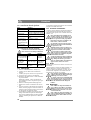
1
4135H - 4155H - 4155 H 4WD
INSTRUCTIONS FOR USE
8211-0069-80
INSTRUCTIONS FOR USE
EN .....7
MODE D’EMPLOI
FR ... 20
GEBRUIKSAANWIJZING
NL .. 34
1
2
3
S
4
2
5
7
6
I
C
F
K
I H
G
D, E
S
9
8
L
L
Q
R
S
K
J
10
K
11
3
13
12
D
B
E
F
G
C
A
15
14
L
M
I
J
K
16
HST
N
4
17
4WD
P
O
18
Q
19
Max
05_119
21
20
R
S
T
0
1
U
V
23
22
Y
5
6
24
25
26
27
28
29
ENGLISH
1.3 References
1 GENERAL
This symbol indicates WARNING. Serious personal injury and/or damage to
property may result if the instructions
are not followed carefully.
You must read these instructions for use
and the accompanying pamphlet
“SAFETY INSTRUCTIONS” carefully, before starting up the machine.
1.1
SYMBOLS
The following symbols appear on the machine.
They are there to remind you of the care and attention required during use and maintenance.
This is what the symbols mean:
Warning!
Read the instruction manual and the safety
manual before using the machine.
Warning!
Watch out for discarded objects. Keep onlookers away.
Warning!
Always wear hearing protectors.
Warning!
This machine is not designed to be driven
on public roads.
Warning!
The machine, equipped with original accessories, must not be driven in any direction on slopes with a gradient greater than
10º.
Warning!
Risk of crushing injuries. Keep hands and
feet well away from the articulated steering joint.
Warning!
Risk of burn injuries. Do not touch the silencer/catalytic converter.
1.2 Designations
Three versions of Park Compact are available and
are designated in the table below:
Machine
4135 H with hydrostatic transmission.
4155 H with hydrostatic transmission.
4155 H with hydrostatic transmission and four wheel drive.
EN
Designation
HST
HST
4WD
1.3.1 Figures
The figures in these instructions for use are numbered 1, 2, 3, etc.
Components shown in the figures are marked A, B,
C, etc.
A reference to component C in figure 2 is written
“2:C”.
1.3.2 Headings
The headings in these instructions for use are numbered in accordance with the following example:
“1.3.1 General safety check” is a subheading to
“1.3 Safety checks” and is included under this
heading.
When referring to headings, only the number of the
heading is normally specified. E.g. “See 1.3.1”.
2 SAFETY INSTRUCTIONS
2.1 GENERAL
• Please read through these instructions carefully.
Learn all the controls and the correct use of the
machine.
• Before use, all drivers must apply for and
receive practical training in the operation of the
machine. Particular emphasis should be placed
on the fact that:
a. The use of ride-on lawnmowers requires care
and concentration.
b. On slopes, it is not possible to control a
sliding ride-on lawnmower by braking. The
main reasons for losing control are insufficient
traction, excessively high speed, insufficient
braking, the machine not being suited to the
task, lack of attention to the surface or incorrect
use as a towing vehicle.
• Never let children or anyone who is not familiar
with these instructions to use the machine.
Local regulations may impose restrictions as
regards the age of the driver.
• Never use the machine if others, particularly
children or animals, are in the vicinity.
• Remember that the driver is responsible for
accidents that happen to other people or their
property.
• Do not let children or other passengers to ride
with you on the machine. They might fall off
and be seriously injured, or they might prevent
the machine being driven safely.
• Do not use the machine if you are under the
influence of alcohol, drugs or medication.
Neither should you use it when you are tired or
feeling unwell.
7
EN
ENGLISH
2.2 PREPARATIONS
• Wear strong shoes and long trousers when using
the machine. Do not operate it barefoot or
wearing sandals.
• Wear appropriate clothing when using the
machine. Do not wear loose, hanging clothes,
jewellery, scarves, ties, etc., which can get
caught in rotating parts. Tie up long hair.
• Carefully check the area that is to be cut/cleared
of snow. Remove all loose stones, sticks, steel
wire and other foreign objects which the
machine could throw out.
• Warning – Petrol is highly inflammable.
a. Always store petrol in containers that are
made especially for this purpose.
b. Only fill or top up with petrol outdoors, and
never smoke when filling or topping up.
c. Fill with petrol before starting the motor.
Never remove the filler cap or fill with petrol
while the engine is running or still warm.
d. If petrol is spilt, do not try to start the engine
but instead move the machine away from the
place where the spillage occurred and avoid any
possible causes of sparks until the petrol fumes
have evaporated.
e. Do not forget to screw the cap on the petrol
tank and the storage container after filling.
• Replace faulty silencers.
• Before use, always check that blades and
mounting devices are not worn or damaged.
Replace worn or damage parts as a set so that
the correct balance is maintained.
• The battery (on electrically started machines)
gives off explosive gases. Keep sparks, flames
and cigarettes away. Ensure there is sufficient
ventilation during charging.
• The battery contains toxic material. Do not
damage the battery casing. If the casing is
damaged, avoid contact with the content of the
battery.
• Do not throw out old, defective batteries with
the rubbish. Contact the local authorities for
correct waste Management.
• Do not short circuit the battery. Sparks occur
which can result in fire.
2.3 DRIVING
• Start the engine according to the instructions in
the user guide. Keep your feet away from the
blades.
• Do not run the engine in confined areas where
hazardous carbon monoxide gases can collect.
• Only use the machine in daylight or where there
is good lighting.
8
• Always use hearing protectors.
• Take care when approaching obstacles which
obscure your vision.
• Always keep children away from the machine’s
working area. Get another adult to keep the
children under supervision.
• Take care when reversing. Look behind you
both before and during reversing to check for
any obstacles. Look out for small children.
• Disengage the blade(s) and the connection
before starting the engine.
• Never have your hands or feet near or under
rotating parts. Watch out for the blades. Do not
stand right in front of the discharge opening.
• Avoid using the machine on wet lawns.
• Be careful when driving on slopes. No sudden
starting or stopping when moving up or down a
slope.
• Release the clutch pedal slowly. Always drive
with the gear engaged, and do not disengage
when driving down slopes.
• Never cut across a slope. Move from the top
down, and from the bottom to the top.
• Use low acceleration when engaging the drive,
especially in long grass. Reduce the speed on
slopes and when making sharp turns to prevent
the machine from tipping over or you losing
control of the machine.
• Watch out for holes in the ground and other
hidden dangers.
• Do not drive too near ditches or high edges.
The machine can turn over if a wheel drives
over the edge or the edge breaks.
• Take care when towing and when using heavy
equipment.
a. Only use an approved towing device.
b. Limit the load so that it can be controlled
safely.
c. Do not make any sudden turns. Take care
when reversing.
d. Use wheel weights or front weight when
recommended in the user instructions.
• Look out for traffic at crossings or when driving
near roads.
• Stop the blade(s) when crossing a surface other
than grass during mowing.
• When using any of the accessories, never direct
the discharge at somebody standing beside it,
and do not allow anyone to stand near the
machine when it is running.
• Never operate the machine with insufficient
protection or without the safety devices in
place.
EN
ENGLISH
• Existing safety devices may not be
disconnected or disengaged. Check that the
safety devices work each time before using the
machine.
• Do not alter the engine’s regulator setting and do
not race the engine. The danger of personal injury
increases when the engine is run at high revs.
• Do not touch engine components which become
warm during use. Risk of burn injuries.
• Do not leave the driving seat without:
a. Disengaging the power take-off and lowering
the accessories.
b. Putting the gear in neutral and activating the
parking brake.
c. Stopping the engine and removing the key.
• Only use accessories that are approved by the
machine’s Manufacturer.
• The machine may not be used without
accessories/tools being installed in the
machine’s tool mounts. Driving without
accessories can have a negative effect on the
stability of the machine.
• Take care when using grass collectors and other
accessories. These can alter the machine’s
stability. Particularly on slopes.
• Disengage the drive to the accessories, shut off
the engine and disconnect the spark plug cable
or remove the starter key:
a. To remove sticks and rubbish or when the
discharge has become clogged.
b. To check, clean or service the machine.
c. To check whether damage has occurred and
to carry out any repairs before starting and
using the machine again after a collision with a
foreign object.
d. To check the machine if it begins to vibrate
excessively. (Check immediately).
• Disengage the drive to accessories during
transport or when the machine is not in use.
• Shut off the engine and disconnect the drive to
the accessories:
a. Before filling with petrol.
b. Before removing the grass collector.
c. Before adjusting the height setting, assuming
this cannot be done from the driver’s position.
• Reduce the acceleration when the engine is to
be stopped, and if the engine is equipped with a
fuel shut-off valve, this should be switched off
when the work is finished.
• Take care with multiple blade decks as one
rotating blade can cause other blades to rotate.
• The machine, equipped with original
accessories, must not be driven in any direction
on slopes with a gradient greater than 10º.
• The cutting deck’s original blade(s) may not be
replaced with non-original devices intended for
e.g. moss scarification. If such devices are used,
the guarantee will cease to be valid. There is
also a risk of serious injury or damage to people
or property.
• Take care when unloading and loading the
machine onto a trailer or lorry.
2.4 MAINTENANCE AND STORAGE
• Tighten all nuts and screws so that the machine
is in safe working condition.
• At regular intervals check that the cutting
deck’s blade screw(s) are properly tightened.
• Regularly check the operation of the brakes. It
is important to maintain and repair the brakes if
necessary.
• Never store the machine with petrol in the tank
in buildings where the fumes can come into
contact with open flames or sparks.
• Allow the engine to cool before placing the
machine in a store.
• To reduce the risk of fire, keep the engine,
silencer, battery and petrol tank free from grass,
leaves and surplus oil.
• Check frequently whether there is any wear or
damage to the grass collector.
• For the sake of safety, replace worn or damaged
parts.
• Always use genuine spare parts. Non-genuine
spare parts can entail a risk of injury, even if
they fit the machine.
• Replace damaged warning and instruction
stickers.
• If there is no mechanical lock for the transport
position, the cutting deck must be lowered
when parked, stored or when the machine is left
unsupervised.
• If the petrol tank is to be emptied, this must take
place outdoors.
• Store the machine so that children cannot get to it.
3 STORAGE
Empty the petrol tank. Start the engine and let it
run until it stops.
Replace the oil while the engine is still warm.
Unscrew the spark plug and pour a tablespoonful
of oil into the cylinder. Rotate the engine a few
turns to that the oil is distributed in the cylinder.
Install the spark plug.
9
EN
ENGLISH
Clean the entire machine. It is particularly
important to clean under the cutting deck. Touch
up paint damage to prevent rust.
Store the machine indoors in a dry place.
Machines with an electric starter:
Remove the battery. Store it well charged in a cool
place (between 0°C and +15°C).
At the correct storage temperature, the battery
should be maintenance-charged every four
months.
The battery acid is extremely corrosive
and can cause injuries and damage to
skin and clothing. Always use rubber
gloves and glasses (goggles) to protect
your eyes. Avoid inhaling any acid
vapour.
Do not incline the battery too much so
that the battery acid can run out onto
hands or clothing. If this should
happen, rinse with plenty of water.
4 ASSEMBLY
To avoid injury and damage to people
and property, do not use the machine
until all the measures in this instruction
have been carried out..
4.1 Accessories bag
The machine is supplied with a plastic bag containing components which shall be used during the assembly. The bag contains (fig. 1):
Pos. No. Designation
Dimension
B
Spare key
C
1
Tension pin
6 x 36
D
1
Shim washer
16 x 38 x 0.5
E
1
Shim washer
16 x 38 x 1.0
F
2
Shoulder washer
G
2
Screw
8 x 20
H
2
Screw knob
I
4
Washer
8.4 x 24 x 1.5
J
1
Drawing plate
K
4
Screw
8 x 20
L
2
Nut
M 2
Screw for battery
N
2
Nut for battery
O
2
Screw
M10 x 35
P
2
Nut
M10
Supplied installed on the front axles:
Pos No. Designation
Q
2
Lock pin
R
2
Washer
Secure to the implement lifter:
Pos No. Designation
S
2
Deck mount
10
4.2 Engine casing
To fill with fuel and to inspect and maintain the engine and battery, open the engine casing.
The engine must not be running when
the casing is opened.
4.2.1Opening
1. Raise the seat lock (fig. 2) and fold the seat forwards.
2. Pull up the rubber strap at the front edge of the
casing (fig. 3).
3. Grasp the front edge of the engine casing and
fold up the casing (fig. 4).
4.2.2 Closing
1. Grasp the front edge of the engine casing and
fold down the casing (fig. 4).
2. Secure the front edge of the casing with the rubber strap (fig. 3).
The machine may not be operated unless the engine casing is closed and
locked. Risk of burns and crushing injuries.
4.3 Battery
See “8.8 Battery”.
4.4 Seat, fig. 6
Release the catch (S) and fold up the seat bracket.
Install the mounting in the rear (upper) holes as
follows:
1. Install the shoulder washers (F) on the screws
(K).
2. Insert the screws through the slots in the bracket. Place a washer (I) between the seat and the
bracket.
3. Tighten the screws in the seat. Tightening
torque: 9±1.7 Nm.
If the screws are tightened more than
9±1.7 Nm, the seat will be damaged.
4. Check that the seat moves easily in the slots in
the bracket.
Install the mounting in the front (lower) holes as
follows:
1. Install the screw knobs (H) on the screws (G).
2. Install a washer (I) on each screw.
3. Insert the screws through the slots in the bracket
and tighten by hand in the seat.
4. Fold the seat down and place it in the desired
position.
5. Tighten the screw knobs (H) by hand.
The screw knobs (H) and the seat will
be damaged if tools are used.
EN
ENGLISH
The seat can be folded. If the machine is parked
outside when it is raining, fold the seat forward to
protect the seat cushion from getting wet.
The seat is locked. To fold the seat up or down, release the catch (S).
4.5 Steering wheel
See fig. 7. In order to minimise the axial play in the
steering column, the shim washers (D) and/or (E)
must be installed on the steering column between
the steering column jacket and the bracket as follows.
1. Install the steering column jacket on the steering column and secure by knocking in the tension pin (C) approximately 1/3 of its length.
2. Pull the steering column jacket and the steering
column up.
3. From the outside, check whether no washers,
the 0.5 mm washer, the 1.0 mm washer or both
washers can be inserted into the gap. The washer/washers must not be forced in, as there must
be a little axial play.
4. Pull out the cotter pin and dismantle the steering
wheel jacket.
5. Install the washer/washers in accordance with
point 3 above.
6. Install the steering column jacket on the steering column and secure by knocking in the tension pin fully. Use a counterhold.
4.6 Towing hitch
See fig. 8. Screw the towing hitch (J) into the two
holes on the underside of the rear axle using screws
(L+K). Tighten the screws properly.
Tightening torque: 22 Nm.
4.7 Deck mounts
This only describes installation on the right-hand
axle. Same procedure must be carried out on the
left-hand axle.
1. Lubricate the axle ends and the deck mount’s
bearing surface with oil before installation.
2. Install the deck mounts to the machine according to fig. 9.
3. Install the locking pin (9:Q) in the hole in the
axle.
4.8 Tyre pressure
Check the air pressure in the tyres. Correct air
pressure:
Front: 0.6 bar (9 psi)
Rear: 0.4 bar (6 psi)
4.9 Accessories
5 DESCRIPTION
5.1
Transmission
5.1.1 HST
The machine is rear wheel drive.
The rear axle is equipped with a hydrostatic transmission with infinitely variable forward and reverse gear ratios.
The rear axle is also equipped with a differential to
facilitate turning.
Front mounted tools are driven by drive belts.
5.1.2 4WD
The machine has 4-wheel drive. The power from
the engine to the drive wheels is transferred hydraulically. The engine drives an oil pump, which
pumps oil through the rear and front axle drives.
The front axle and rear axle are connected in series, which means that the front wheels and rear
wheels are forced to rotate at the same speed.
To make turning easier, both axles are equipped
with differential.
Front-mounted implements are powered via drive
belts.
5.2
Steering
5.3
Safety system
The machine is articulated. This means that the
chassis is divided into a front and a rear section,
which can be turned in relation to each other.
The articulated steering means that the machine
can turn around trees and other obstacles with an
extremely small turning radius.
The machine is equipped with an electrical safety
system. The safety system interrupts certain activities that can entail a danger of incorrect manoeuvres. For example, the engine cannot be started if
the clutch-parking brake pedal is depressed.
The operation of the safety system must
always be checked every time before
use.
5.4 Controls
5.4.1 Implement lifter, mechanical (12:A)
To switch between working position and transport
position:
1. Depress the pedal fully.
2. Release the pedal slowly.
For the installation of accessories, see separate installation guide supplied with each accessory.
Note: The cutting deck is regarded as an accessory
here.
11
EN
ENGLISH
5.4.2 Clutch-parking brake (12:B)
Never press the pedal while driving.
There is a risk of overheating in the
power transmission.
The pedal has the following
three positions:
• Released. The clutch is not activated. The parking brake is not activated.
• Depressed halfway. Forward drive disengaged.
The parking brake is not activated.
• Fully depressed. Forward drive disengaged.
The parking brake is fully activated but not
locked. This position is also used as emergency
brake.
5.4.3 Inhibitor, parking brake (12:C)
The inhibitor locks the “clutch-brake”
pedal in the depressed position. This function is used to lock the machine on slopes,
during transport, etc., when the engine is
not running.
Locking:
1. Depress the pedal (14:B) fully.
2. Move the inhibitor (14:C) to the right.
3. Release the pedal (14:B).
4. Release the inhibitor (14:C).
Unlocking:
Press and release the pedal (14:B).
5.4.4 Driving-service brake (12:F)
If the machine does not brake as expected when the pedal is released, the left
pedal (12:B) should be used as an emergency brake.
The pedal determines the gearing ratio between the
engine and the drive wheels (= the speed). When
the pedal is released, the service brake is activated.
1. Press the pedal forward –
the machine moves forward.
2. No load on the pedal – the machine is stationary.
3. Press the pedal backward –
the machine reverses.
4. Reduce the pressure on the
pedal – the machine brakes.
5.4.5 Throttle and choke control (12:D)
A control for setting the engine speed and to choke
the engine when starting from cold.
If the engine runs unevenly there is a
risk that the control is too far forward
so that the choke is activated. This damages the engine, increases fuel consumption and is harmful to the
environment.
1. Choke – for starting a cold engine. The
choke position is located at the front of the
groove.
Do not operate in this position when the
engine is warm.
2. Full throttle – when the machine is in
operation, full throttle should always be
used.
The full throttle position is approximately
2 cm behind the choke position.
3. Idling.
5.4.6 Ignition lock (12:E)
Do not leave the machine with the key
in position 2 or 3. There is a fire risk,
fuel can run into the engine through the
carburettor, and there is a risk of the
battery being discharged and damaged.
Ignition lock used for starting/stopping the engine.
Four positions:
1. Stop position – the engine is shortcircuited. The key can be removed.
2/3. Operating position.
4. Start position – the electric start motor
is activated when the key is turned to the
spring-loaded start position. Once the engine has started, let the key return to operating position 2/3.
5.4.7 Power take-off (13:G)
The power take-off must never be
engaged when the front-mounted
implement is in transport position. This
will destroy the belt transmission.
A lever for engaging and disengaging the power
take-off for operating front-mounted accessories.
Two positions:
1. Lever in forward position – power takeoff disengaged.
2. Lever in backward position - power
take-off engaged.
12
EN
ENGLISH
5.4.8 Clutch release lever
A lever for disengaging the variable transmission.
HST is equipped with a lever, connected to the rear
axle. See (16:N).
4WD is equipped with two levers, connected to the
rear axle (17:O) and the front axle (17:P).
The disengagement lever must never be
between the outer and inner positions.
This overheats and damages the transmission.
The levers enable the machine to be moved by
hand without the help of the engine. Two positions:
1. Lever in the inner position –
transmission engaged for normal
operation.
2. Lever in the outer position –
transmission disengaged. The
machine can be moved by hand.
The machine may not be towed over long distances
or at high speeds. The transmission could be damaged.
The machine must not be operated with
the forward most lever in the outer position. Risk of damage and oil leakage in
the front axle.
5.4.9 Seat (14:I)
The seat can be folded and is adjustable
front-rear. The seat is locked in the folded
up position using the catch (14:K) and adjusted front-rear using the knobs (14:J).
The seat is equipped with a safety switch that is
connected to the machine’s safety system. This
means that certain dangerous activities are not possible when there is nobody in the seat.
5.4.10 Engine casing (15:L)
To access the fuel cock, battery and engine
the engine is equipped with engine casing
that can be opened. The engine casing is
locked by a rubber strap.
The engine casing is opened as follows:
1. Detach the rubber strap (15:M) at the front edge
of the engine casing.
2. Carefully lift the engine casing back.
Close in reverse order.
The machine may not be operated unless the engine casing is folded down
and locked. Risk of burns and crushing
injuries.
6 AREAS OF USE
The machine may only be used for the following
tasks using the genuine GGP accessories stated.
Operation
Accessories, GGP original
Mowing
With cutting deck 95 C (all).
With cutting deck 105 C (only
4155 H).
Snow clearance With snow blade. Snow chains
and frame weights recommended.
Grass clipping and With towed collector 30" or 42".
leaf collection
Grass and leaf
With dump cart Pro or Combi.
transport
The maximum vertical load on the towing hitch
must not exceed 100 N.
The maximum over-run load on the towing hitch
from towed accessories must not exceed 500 N.
NOTE! Before using a trailer – contact your insurance company.
NOTE! This machine is not intended to be driven
on public roads.
7 STARTING AND OPERATION
The machine may not be operated unless the engine casing is closed and
locked. Risk of burns and crushing injuries.
7.1
Filling with petrol (18:Q)
Always use lead-free petrol. You must never use 2stroke petrol mixed with oil.
The tank holds 6 litres. The level can easily be read
through the transparent tank.
NOTE! Ordinary lead-free petrol is a perishable
and must not be stored for more than 30 days.
Environmental petrol can be used, i.e. alkylate
petrol. This type of petrol has a composition that is
less harmful for people and nature.
Petrol is highly inflammable. Always
store fuel in containers that are made
especially for this purpose.
Only fill or top up with petrol outdoors,
and never smoke when filling or topping up. Fill up with fuel before starting
the engine. Never remove the filler cap
or fill with petrol while the engine is
running or still warm.
13
EN
ENGLISH
Never completely fill the petrol tank. Leave an
empty space (= at least the entire filler tube plus 1
- 2 cm at the top of the tank) to allow the petrol to
expand when it warms up without overflowing.
See fig. 18.
7.2 Checking the engine oil level
On delivery, the crankcase is filled with SAE 10W30 oil.
Check the oil level every time before using to
ensure it is correct. The machine should be
standing on level ground.
Wipe clean around the oil dipstick. Unscrew and pull it up. Wipe off the dipstick.
Slide it down completely and tighten it.
Then unscrew it and pull it up again. Read off the
oil level. Top up with oil to the “FULL” mark, if
the level comes below it. See fig. 19.
The oil level must never exceed the “FULL” mark.
This results in the engine overheating. If the oil
level exceeds the “FULL” mark, the oil must be
drained until the correct level is achieved.
7.3 Checking transmission oil level
Check the oil level every time before using to
ensure it is correct. The machine should be
standing on level ground.
Read off the oil level in the reservoir (20:R). It
should be between the MAX and MIN marks. If
necessary, top up with more oil.
Type of oil:
Oil type
4WD
Synthetic oil 5W-50
HST
SAE 10W-30 (20W-50)
7.4.1 General safety check
Object
Result
Fuel lines and con- No leaks.
nections.
Electrical cables. All insulation intact.
No mechanical damage.
Exhaust system.
No leaks at connections.
All screws tightened.
Oil lines
No leaks. No damage.
Drive the machine The machine will stop.
forwards/backwards and release
the driving-service
brake pedal.
Test driving
No abnormal vibrations.
No abnormal sound.
7.4.2 Electrical safety check
The operation of the safety system
should always be checked every time
before use.
Status
The clutch-brake
pedal not
depressed.
Power take-off not
activated.
Engine running.
Power take-off
activated.
Engine running.
7.5
7.4
Safety checks
Check that the results of the safety checks below
are achieved when testing the machine in question.
The safety checks must always be carried out every time before use.
If any of the results below is not
achieved, the machine must not be
used! Take the machine to a service
workshop for repair.
14
Start
Action
Attempt to start.
Result
The engine
must not
start.
The operator
leaves the seat.
The power
take-off
must disengage.
Remove the fuse. The engine
See 20:S.
must stop.
1. Open the fuel cock. See (21:U).
2. Check that the spark plug cable(s) is/are installed on the spark plug(s).
3. Check to make sure that the power take-off is
disengaged.
4. Do not keep your foot on the drive pedal.
5. Starting cold engine – put the throttle control in
the choke position.
Starting warm engine – put the throttle control
at full throttle (approx. 2 cm behind the choke
position).
6. Depress the clutch-brake pedal fully.
7. Turn the ignition key and start the engine.
8 Once the engine has started, move the throttle
control gradually to full throttle (approx. 2 cm
behind the choke position) if the choke has been
used.
EN
ENGLISH
9. When starting from cold, do not make the machine work under load immediately, but let the
engine run for a few minutes first. This will allow the oil to warm up.
When the machine is in operation, full throttle
should always be used.
7.6
Operating tips
Always check that there is the correct volume of
oil in the engine. This is particularly important
when operating on slopes. See 7.2 Checking the
engine oil level.
Be careful when driving on slopes. No
sudden starting or stopping when driving up or down a slope. Never drive
across a slope. Move from the top down
or from the bottom to the top.
The machine may not be driven on
slopes greater than 10º in any direction.
Reduce the speed on slopes and when
making sharp turns in order to retain
control and reduce the risk of tipping
over.
Do not turn the steering wheel to full
lock when driving in top gear and at full
throttle. The machine can easily topple
over.
Keep hands and fingers well away from
articulated steering joint and seat
bracket. Risk of crushing injuries. Never drive with the engine casing open.
7.7
8 MAINTENANCE
8.1 Service programme
In order to keep the machine in good condition as
regards reliability and operational safety as well as
from an environmental perspective, GGP’s Service
programme should be followed.
Servicing carried out at an authorised workshop
guarantees professional work using genuine spare
parts.
8.2
Cleaning
To reduce the risk of fire, keep the engine, silencer, battery and fuel tank free
from grass, leaves and oil.
To reduce the risk of fire, regularly
check the machine for oil and/or fuel
leakage.
Preparation
All service and all maintenance must be carried out
on a stationary machine with the engine switched
off.
Prevent the machine from rolling by always applying the parking brake.
Stop the engine.
Stop
Disengage the power take-off. Apply the parking
brake.
Allow the engine to idle 1-2 mins. Stop the engine
by turning off the ignition key.
Shut off the petrol cock. This is particularly important if the machine is to be transported on a trailer
for example.
If the machine is left unattended, remove the spark plug cable(s) and remove the ignition key.
The engine may be very warm immediately after it is shut off. Do not touch the
silencer, cylinder or cooling fins. This
can cause burn injuries.
7.8
Clean the machine after each use. The following
instructions apply for cleaning:
• When washing the machine with water under
high pressure, do not point the jet directly at
axle seals, electrical components or hydraulic
valves.
• Do not spray water directly at the engine.
• Clean the engine with a brush and/or compressed air.
• Clean the engine’s cooling air intake (20:T).
Prevent unintentional starting of the
engine by disconnecting the spark plug
cable(s) from the spark plug(s) and removing the ignition key.
8.3
Tyre pressure
8.4
Changing engine oil
Adjust the air pressure in the tyres as follows:
Front: 0.6 bar (9 psi).
Rear: 0.4 bar (6 psi).
Change engine oil for the first time after 5 hours of
operation, and subsequently after every 50 hours
of operation or once a season.
Change the oil more often (after 25 hours of operation or at least once a season) if the engine has to
operate under demanding conditions or if the ambient temperature is high.
Use oil according to the table below.
Oil
SAE 10W-30
Service class
SJ or higher
Use oil without any additives.
15
EN
ENGLISH
Do not fill with too much oil. This can cause the
engine to overheat.
Change oil when the engine is warm.
The engine oil may be very hot if it is
drained off directly after the engine is
shut off. Therefore allow the engine to
cool a few minutes before draining the
oil.
1. Attach the clamp on the oil drainage hose. Use
a polygrip or similar. See fig. (21:V).
2. Move the clamp up 3-4 cm on the oil drainage
hose and pull out the plug.
3. Collect the oil in a collection vessel.
NOTE! Do not spill any oil on the drive belts.
4. Hand in the oil for disposal in accordance with
local provisions.
5. Install the oil drainage plug and move the clamp
back so that it clamps above the plug.
6. Remove the dipstick and fill up with new oil.
Oil volume: 1.4 litres
7. After filling up the oil, start the engine and idle
for 30 seconds.
8. Check to see if there is any oil leakage.
9. Stop the engine. Wait for 30 seconds and then
check the oil level in accordance with 7.2
Checking the engine oil level.
8.5 Transmission, oil (4WD)
The oil in the hydraulic power transmission must
be checked/adjusted and changed at the intervals
given in the table below.
1st time Then at
intervals
Action
of
Hours of operation
Checking – adjusting level.
50
Changing the oil.
50
200
Type of oil: Synthetic oil 5W-50
Oil quantity when changing: approximately 3.5 litres.
8.5.1 Checking - adjusting
Se “7.2 Checking the engine oil level”.
8.5.2 Draining
1. Run the machine at variable speeds for 10-20
minutes to heat up the transmission oil.
2. Position the machine completely horizontally.
3. Pull out both disengagement levers according to
fig. 17.
4. Place one container under the rear axle and one
under the front axle.
5. Open the oil reservoir by removing the cover.
See (20:R).
16
Only a 3/8” square drive may be used
for the oil plug. Other tools will damage
the plug.
6. Remove the oil plug from the rear axle. Clean
the hole and use a 3/8” square drive. See figure
22.
7. Remove 2 drain plugs from the front axle. Use
a 12 mm socket. Allow the oil in the front axle
and pipes to run out. See fig. 23.
8. Check that the gaskets on the drain plugs of the
front axle are intact. See fig. 23. Reinstall the
plugs. Tightening torque: 15-17 Nm.
The oil plug will be damaged if it is
tightened more to than 5 Nm.
9. Check that the gasket on the oil plug of the rear
axle is intact. See fig. (22:Y). Reinstall in the
rear axle. Tighten the oil plug to 5 Nm.
10.Draw out the oil from the deeper section of the
reservoir using an oil extractor. See fig. 24.
11.Dispose of the oil according to local regulations.
8.5.3 Filling
The engine must never be run when the
rear clutch release lever is pushed in
and the front clutch release lever is
pulled out.
This will damage the front axle seals.
1.Fill the oil reservoir with the new oil.
If the engine is run indoors, exhaust extraction equipment must be connected
to the engine’s exhaust pipe.
2. Check that the rear axle’s clutch release lever is
pulled out.
3. Start the engine. When the engine is started, the
front axle’s clutch release lever slides inwards
automatically.
4. Pull out the front axle’s clutch release lever.
NOTE! The oil is drawn into the system very
quickly. The reservoir must always be
topped up. Air must never be drawn in.
5. Set the accelerator pedal to the forward position
by blocking it using a wooden wedge. See fig.
25. Fill the oil reservoir by hand using new oil.
6. Run in the forward position for one minute.
7. Move the wooden wedge and set the accelerator
pedal to the reverse position. Continue filling
with oil.
8. Run in reverse mode for one minute.
9. Change driving direction once every minute as
above and continue filling with oil until the
bubbling in the reservoir stops.
10.Switch off the engine, install the oil reservoir
cover and close the engine cover.
11.Test drive for several minutes and adjust the oil
level in the reservoir.
EN
ENGLISH
8.6 Belt transmissions
After 5 hours of operation, check that all the belts
are intact and undamaged.
8.7 Steering
The steering must be checked/adjusted after 5
hours of operation and thereafter after 100 hours of
operation.
8.7.1 Checks
Briefly turn the steering wheel back and forth.
There must be no mechanical clearance in the
steering chains.
8.7.2 Adjustment
Adjust the steering chains if required as follows:
1. Put the machine in the straight-ahead position.
2. Adjust the steering chains with the two nuts, located under the central point. See fig. 27.
3. Adjust both nuts by the same amount until there
is no clearance.
4. Test drive the machine straight forwards and
check that the steering wheel is not off centre.
5. If the steering wheel is off centre, undo one nut
and tighten the other.
Do not over-tighten the steering chains. This will
cause the steering to become heavy and will increase wear on the steering chains.
8.8 Battery
If acid comes into contact with the eyes
or skin, this can cause serious injuries.
If any part of the body has come into
contact with acid, rinse immediately
with copious amounts of water and seek
medical assistance as soon as possible.
The battery is a valve-regulated battery with 12 V
nominal voltage. The battery fluid does not need to
and cannot be checked or topped up. The only
maintenance that is required is charging, for example after extended storage.
The battery must be fully charged before being used for the first time. The
battery must always be stored fully
charged. If the battery is stored while
discharged, serious damage will occur.
8.8.1 Charging with the engine
The battery can be charged using the engine’s generator as follows:
1. Install the battery in the machine as shown below.
2. Place the machine outdoors or install an extraction device for the exhaust fumes.
3. Start the engine according to the instructions in
the user guide.
4. Allow the engine to run continuously for 45
minutes.
5. Stop the engine. The battery will now be fully
charged.
8.8.2 Charging using battery charger
When charging using a battery charger, a battery
charger with constant voltage must be used.
Contact your dealer to purchase a battery charger
with constant voltage.
The battery can be damaged if a standard type
battery charger is used.
8.8.3 Removal/Installation
The battery is placed under the engine casing. During removal/installation, the following applies regarding connection of the cables:
• During removal. First disconnect the black cable from the battery’s negative terminal (-).
Then disconnect the red cable from the battery’s
positive terminal (-).
• During installation. First connect the red cable
to the battery’s positive terminal (+). Then connect the black cable to the battery’s negative terminal (-).
If the cables are disconnected/connected in the wrong order, there is a risk of
a short-circuit and damage to the battery.
If the cables are interchanged, the generator and the battery will be damaged.
Tighten the cables securely. Loose cables can cause a fire.
The engine must never be driven with
the battery disconnected. There is a risk
of serious damage to the generator and
the electrical system.
8.8.4 Cleaning
If the battery terminals are coated with oxide, they
should be cleaned. Clean the battery terminals with
a wire brush and lubricate them with terminal
grease.
8.9
Air filter, engine
The pre-filter (foam filter) must be cleaned/replaced after 25 hours of operation.
The air filter (paper filter) must be cleaned/replaced after 100 hours of operation.
NOTE! The filters should be cleaned/replaced
more often if the machine operates on dusty
ground.
Remove/install the air filters as follows.
1. Clean carefully around the air filter cover.
2. Dismantle the air filter cover (26:A) by removing the two clamps.
17
EN
ENGLISH
3. Dismantle the filter assembly (26:B). The prefilter is placed over the air filter. Make sure that
no dirt gets into the carburettor. Clean the air filter housing.
4. Clean the paper filter by tapping it gently
against a flat surface. If the filter is very dirty,
replace it.
5. Clean the pre-filter. If the filter is very dirty, replace it.
6. Assemble in the reverse order.
Compressed air or petroleum-based solvents such
as kerosene may not be used for cleaning the paper
filter insert. This will damage the filter.
8.13 Fuse
In the event of electrical faults, check/replace the
fuse, 20 A. See 20:S.
9 PATENT - DESIGN REGISTRATION
This machine or parts thereof is covered by the following patent and design registration:
SE9901091-0, SE9901730-3, SE9401745-6,
US595 7497, FR772384, DE69520215.4,
GB772384, SE0301072-5, SE04/000239 (PCT),
SE0401554-1, SE0501599-5.
8.10 Spark plug
The spark plug(s) must be replaced every 200
hours of operation (=at every other basic service).
Before disconnecting the spark plug, clean around
its mounting.
Spark plug: Champion RC12YC or equivalent.
Electrode distance: 0.75 mm.
8.11 Air intake
See 19:T. The engine is air-cooled. A blocked
cooling system can damage the engine. Clean the
engine’s air intake after 50 hours of operation.
More meticulous cleaning of the cooling system is
carried out during each basic service.
8.12 Lubrication
All lubrication points in accordance with the table
below must be lubricated every 50 hours of operation as well as after every wash.
Object
Action
Figure
Centre point 4 grease nipples.
28
Use a grease gun filled with
universal grease. Pump until
the grease emerges.
Steering
Brush the chains clean with
chains
a wire brush.
Lubricate with universal
chain spray.
Tensioning Lubricate the bearing points
29
arms
with an oil can when each
control is activated.
Ideally carried out by two
people.
Control
Lubricate the cable ends
29
cables
with an oil can when each
control is activated.
Must be carried out by two
people.
18
10 SERVICE
Authorised service workshops carry out repairs
and guarantee service. They use original spare
parts.
Original spare parts are supplied by service
workshops and by Many dealers.
We recommend that the machine be handed in to
an authorised service workshop for service,
maintenance and checking of the safety devices
once a year.
11 PURCHASE TERMS
A full guarantee is issued against Manufacturing
and material defects. The user must carefully follow the instructions given in the enclosed documentation.
Guarantee period
For consumer use: two years from purchase date.
For batteries: six months from the purchase date.
Exceptions
The guarantee does not cover damage due to:
- neglect of the user to acquaint himself with accompanying documentation
- carelessness
- incorrect and non-permitted use or assembly
- the use of non-genuine spare parts
- the use of accessories not supplied or approved
by GGP
Neither does the guarantee cover:
- wearing components such as blades, belts,
wheels and cables
- normal wear
- engine and transmission. These are covered by
the appropriate Manufacturer’s guarantees with
separate terms and conditions.
The purchaser is covered by each country’s
national laws. The rights to which the purchaser is
entitled with the support of these laws are not
restricted by this guarantee.
ENGLISH
12 ENVIRONMENT
For environmental reasons, we recommend that
particular attention is given to the following
points:
• Always use Alkylate petrol (“Environmental
petrol“).
• Always use a funnel and/or a petrol can with
overfill protection to avoid spillage when filling
with petrol.
• Do not fill the petrol tank right to the top.
• Do not fill too much engine and/or transmission
oil (see user instructions for the correct
amount).
• Collect up all oil during oil changes. Do not
spill any. Hand in the oil to a recycling station.
• Do not discard replaced oil filters with normal
rubbish. Hand them in to a recycling station.
• Do not discard replaced lead batteries with
normal rubbish. Hand in to a battery collection
point for recycling.
• Replace the silencer if it is broken. Always use
original spare parts when carrying out repairs.
• If the machine was originally equipped with a
catalytic converter and this is broken, a new
catalytic converter must be installed after
removing the old one.
• Always get a specialist to adjust the carburettor
if necessary.
Clean the air filter according to the instructions
given (see user instructions).
EN
13 PRODUCT IDENTITY
The identity of the product is determined by two
parts:
1. The machine’s item and serial numbers:
2. The engine’s model, type and serial numbers:
Found on the machine’s fan housing as illustrated:
Use these identification terms during all contact
with service workshops and when purchasing
spare parts.
As soon as possible after acquiring the machine,
the above number should be written in on the last
page of this publication.
GGP reserves the right to make alterations to the
product without prior notification.
19
FR
FRANÇAIS
1.3 Références
1 GÉNÉRALITÉS
Ce symbole est un AVERTISSEMENT.
Risque de blessure ou de dégât matériel
en cas de non-respect des instructions.
Avant de démarrer la machine, lire attentivement les instructions ainsi que
les consignes contenues dans le fascicule
« RÈGLES DE SÉCURITÉ » ci-joint.
1.1
Symboles
Les symboles suivants figurent sur la machine. Ils
attirent votre attention sur les dangers et les
mesures à respecter lors de l’utilisation et de la
maintenance.
Explication des symboles :
Attention!
Lire le mode d’emploi et le manuel de sécurité avant d’utiliser la machine.
Attention!
Attention aux projections. Travailler à une
distance suffisante de toute présence.
Attention !
Porter des protections auditives.
Attention !
Cet engin n’est pas conçu pour circuler sur
la voie publique.
Attention !
La machine, équipée d’accessoires d’origine, ne peut en aucun cas être utilisée sur
des pentes dont l’inclinaison est
supérieure à 10°.
Attention !
Risque de blessure par écrasement. Garder
les mains et les pieds à distance du joint de
direction articulé.
Attention !
Ne pas les toucher sous peine de se brûler.
Ne pas toucher le silencieux ou le convertisseur catalytique.
1.2 Désignation
Park Compact existe en 3 versions :
Machine
4135 H à transmission hydrostatique.
4155 H à transmission hydrostatique.
4155 H à transmission hydrostatique et quatre roues motrices.
20
Désignation
HST
HST
4WD
1.3.1 Numérotation
Dans les instructions qui suivent, les figures sont
numérotées 1, 2, 3, etc.
Les composants illustrés sont indiqués par A, B, C,
etc.
Une référence renvoyant à l’élément C de la figure
2 sera indiqué « 2:C ».
1.3.2 Titres
Les titres sont numérotés selon l’exemple suivant :
« 1.3.1 Contrôle de sécurité générale » est un soustitre intégré au chapitre « 1.3 Contrôles de sécurité
».En principe, lorsqu’on renvoie à un titre, seul son
numéro est indiqué, par ex. « Voir 1.3.1 ».
2 RÈGLES DE SÉCURITÉ
2.1 GÉNÉRALITÉS
• Veuillez lire attentivement les instructions qui
suivent et apprendre les commandes et le
maniement correct de la machine avant de
l’utiliser.
• Les utilisateurs de la tondeuse doivent suivre
une formation pratique préalable. Soyez
particulièrement attentif au fait que :
a. L’utilisation de tondeuses autoportées
requiert de l’attention et de la concentration.
b. Si on perd le contrôle d’une tondeuse
autoportée sur un terrain en pente, il est
impossible de le récupérer en freinant.
Principales causes des pertes de contrôle :
traction insuffisante, vitesse excessive, freinage
insuffisant, machine inadaptée à la tâche à
exécuter, manque d’attention sur les
irrégularités du terrain et présence d’une
remorque.
• Ne jamais confier l’utilisation de la tondeuse à
des enfants ou à des personnes
inexpérimentées. L’âge minimum du
conducteur est déterminé par les
réglementations locales.
• Ne pas tondre à proximité de personnes, en
particulier des enfants, ou d’animaux.
• Le conducteur de l’engin assume seul la
responsabilité des accidents impliquant des
personnes ou des biens.
• Ne pas embarquer de passagers à bord de la
tondeuse. Ils pourraient se blesser en cas de
chute ou gêner les manœuvres du conducteur.
• Ne pas conduire la machine sous l’influence de
l’alcool, de drogues, de substances
médicamenteuses, ni en cas de fatigue ou de
malaise.
FRANÇAIS
2.2 PRÉCAUTIONS
• Pour utiliser la machine, le port de chaussures
renforcées et d’un pantalon est recommandé.
Ne pas tondre à pieds nus ou en sandales.
• Porter des vêtements appropriés. Ne pas porter
de vêtements amples ou flottants, de bijoux,
écharpes, cravates, etc. susceptibles de se
prendre dans les pièces en rotation. Attacher les
cheveux longs.
• Contrôler attentivement la zone à tondre ou à
déneiger. Retirer toutes les pierres, bouts de
bois, fils de fer et autres objets étrangers qui
pourraient être éjectés par la machine.
• Attention – l’essence est très inflammable.
a. Toujours conserver l’essence dans des
récipients spécialement conçus à cet effet.
b. Faire le plein d’essence uniquement à
l’extérieur, et ne pas fumer pendant l’opération.
c. Faire le plein d’essence avant de démarrer le
moteur. Ne jamais retirer le bouchon du
réservoir et ne pas ajouter d’essence lorsque le
moteur tourne ou tant qu’il est chaud.
d. Si de l’essence se répand, ne pas démarrer le
moteur. Déplacer la tondeuse en la poussant
pour l’éloigner de la flaque d’essence et veiller
à ce qu’aucune étincelle ne se produise tant que
l’essence ne s’est pas évaporée.
e. Ne pas oublier de revisser le bouchon du
réservoir et du jerrycan après avoir fait le plein.
• Remplacer les pots d’échappement défectueux.
• Avant l’emploi, vérifier l’état des lames et de
leur support. Si ces éléments sont usés ou
endommagés, les remplacer complètement pour
conserver l’équilibre du dispositif.
• La batterie (sur les machines à démarreur
électrique) dégage des gaz explosifs. La
conserver à l’écart des étincelles, flammes et
cigarettes. Veiller à une bonne aération pendant
que la batterie est en charge.
• La batterie contient des matériaux toxiques.
Veiller à ne pas l’endommager. Si l’extérieur de
la batterie est endommagé, éviter tout contact
avec son contenu.
• Ne pas jeter les batteries usées ou défectueuses
dans les poubelles. Renseignez-vous auprès de
votre administration pour savoir comment vous
en débarrasser en respectant l’environnement.
• Ne pas provoquer de court-circuit dans la
batterie. Cela provoquerait des étincelles
susceptibles de mettre le feu.
2.3 CONDUITE
• Suivre les instructions du manuel pour démarrer
le moteur. Tenir les pieds à l’écart des lames.
• Ne pas démarrer le moteur dans des espaces
•
•
•
•
•
•
•
•
•
•
•
•
•
•
•
•
•
•
•
•
•
•
FR
confinés où il existe un risque d’intoxication au
monoxyde de carbone.
Utiliser la machine uniquement à la lumière du
jour ou dans des zones bien éclairées.
Porter des protections auditives.
Redoubler de vigilance à proximité d’obstacles
qui masquent la vue.
Tenir les enfants à l’écart, sous la surveillance
d’un adulte.
Faire attention en changeant de direction.
Regarder derrière soi avant et pendant la
marche arrière pour vérifier l’absence
d’obstacles. Faire particulièrement attention aux
enfants en bas âge.
Débrayer les lames et se mettre au point mort
avant de démarrer le moteur.
Ne pas approcher les mains et les pieds des
pièces en rotation. Attention aux lames. Ne pas
se tenir devant l’orifice d’évacuation.
Éviter de tondre les pelouses humides.
Être particulièrement vigilant sur les terrains en
pente. Ne pas démarrer ou s’arrêter brutalement
sur un terrain en pente.
Débrayer progressivement. Rester en vitesse
pendant toute la conduite et ne pas débrayer en
descente.
Ne jamais tondre en suivant une trajectoire
transversale à la pente. Se déplacer de haut en
bas, et de bas en haut.
Accélérer lentement pour engager une vitesse,
surtout si la pelouse est haute. Ralentir dans les
pentes et dans les virages pour éviter de
basculer ou de perdre le contrôle de la machine.
Éviter les trous dans le sol et les autres dangers
potentiels.
Rester à distance des fossés et des bordures
hautes. La machine risque de se renverser si la
roue passe sur la bordure ou si la bordure
s’effondre.
Prudence en cas de remorquage et d’utilisation
de matériel lourd.
a. N’utiliser que des dispositifs de
remorquage agréés.
b. Limiter la charge pour en garder le
contrôle en toute sécurité.
c. Ne pas effectuer de virage brusque. Faire
attention en changeant de direction.
d. Placer des poids sur les roues ou à l’avant
de la tondeuse. Voir manuel.
Faire preuve de prudence à l’approche d’un
carrefour ou d’une route.
Arrêter les lames sur les surfaces autres que de
la pelouse.
Lorsque des accessoires sont montés sur la
21
FR
•
•
•
•
•
•
•
•
•
•
•
•
•
•
•
•
•
•
•
•
•
•
22
FRANÇAIS
tondeuse, ne jamais diriger l’évacuation vers
des personnes se trouvant dans les parages.
Écarter toute présence à proximité d’une
tondeuse en marche.
Ne jamais utiliser la machine si les protections
et dispositifs de sécurité sont insuffisants.
Il est interdit de déconnecter les dispositifs de
sécurité ou d’en empêcher le fonctionnement.
Vérifier l’état des dispositifs de sécurité avant
chaque utilisation de la machine.
Ne pas modifier le réglage du moteur. Ne pas
pousser le moteur à plein régime. Le risque de
blessure augmente lorsque le moteur tourne à
plein régime.
Certains éléments du moteur chauffent pendant
l’utilisation. Ne pas les toucher sous peine de se
brûler.
Avant de quitter le siège du conducteur :
a. Neutraliser la prise de force et abaisser les
accessoires.
b. Engager le point mort et serrer le frein à
main.
c. Arrêter le moteur et retirer la clé.
Utiliser exclusivement des accessoires
approuvés par le fabricant.
Ne pas utiliser la machine si les accessoires/
outils ne sont pas fixés sur le châssis prévu à cet
effet. L’utilisation de la tondeuse sans
accessoires peut réduire sa stabilité.
Attention : les bacs de ramassage et autres
accessoires peuvent réduire la stabilité de la
machine, surtout sur les terrains en pente.
Immobiliser les accessoires, couper le moteur et
débrancher la bougie ou enlever la clé du
démarreur pour :
a. Retirer les branchages et autres éléments qui
bouchent l’évacuation.
b. Inspecteur, nettoyer ou entretenir la machine.
c. Vérifier les éventuels dégâts et procéder aux
réparations qui s’imposent avant de pouvoir
réutiliser la machine à la suite d’un impact avec
un corps étranger.
d. Inspecter la machine si elle se met à vibrer
excessivement. (Vérifier immédiatement.)
Immobiliser les accessoires pendant le transport
ou lorsque la machine est arrêtée.
Couper le moteur et immobiliser les accessoires
avant de :
a. faire le plein de carburant.
b. retirer le bac de ramassage.
c. régler la hauteur, pour autant que cette
opération ne puisse s’effectuer sans quitter le
siège du conducteur.
Ralentir avant de couper le moteur. Si l’arrivée
•
•
•
•
d’essence est équipée d’un robinet d’arrêt,
fermer celui-ci à la fin du travail.
Attention : sur les plateaux à lames multiples,
une lame peut en entraîner une autre dans sa
rotation.
La machine, équipée d’accessoires d’origine,
ne peut en aucun cas être utilisée sur des pentes
dont l’inclinaison est supérieure à 10°.
Les lames originales ne peuvent être
remplacées par des systèmes d’autres marques
conçus, par ex. pour la scarification de la
mousse. En cas d’utilisation de ces systèmes, la
garantie cesse d’être valable. En outre,
l’utilisation de matériel non conforme
représente un danger pour les personnes et les
biens.
Le chargement et déchargement de la machine
sur un tracteur ou un camion doit s’effectuer
avec prudence.
2.4 MAINTENANCE ET REMISAGE
• Serrer tous les boulons et vis pour assurer la
sécurité de la machine.
• Contrôler régulièrement le serrage des vis des
lames.
• Contrôler régulièrement le fonctionnement des
freins. L’entretien et l’éventuelle réparation des
freins est un point vital.
• Ne pas stationner la machine à l’intérieur si son
réservoir contient du carburant dont les
émanations sont susceptibles d’entrer en
contact avec des flammes nues ou des
étincelles.
• Laisser refroidir le moteur avant de ranger la
machine dans un local.
• Pour réduire le risque d’incendie, dégager
l’herbe, les feuilles et l’excédent d’huile se
trouvant sur le moteur, le pot d’échappement, la
batterie et le réservoir.
• Vérifier régulièrement l’état du bac de ramassage.
• Pour garantir la sécurité, remplacer les pièces
usées ou endommagées.
• N’utiliser que des pièces d’origine.
L’utilisation d’autres types de pièces de
rechange, même si elles s’adaptent à la
machine, peut se révéler dangereuse.
• Remplacer les autocollants d’avertissement et
d’instructions devenus illisibles.
• Si la machine n’est pas pourvue d’un dispositif
de blocage pour le transport, le plateau de coupe
doit être abaissé lorsque la machine est
stationnée, rangée ou laissée sans surveillance.
• La vidange éventuelle du réservoir de carburant
doit s’effectuer à l’extérieur.
FR
FRANÇAIS
• La machine doit être entreposée hors de portée
des enfants.
• La batterie contient de l’acide. En cas de
surcharge ou de dégâts, il peut y avoir une fuite
d’acide.
• Ne jamais surcharger la batterie pour éviter
qu’elle explose en projetant de l’acide dans tous
les sens.
• Les projections d’acide dans les yeux ou sur la
peau peuvent provoquer des blessures graves.
En cas de contact avec de l’acide, rincer
abondamment à l’eau claire et consulter le plus
rapidement possible un médecin.
• L’inhalation de vapeurs d’acide peuvent
provoquer des lésions des muqueuses et des
organes internes. Consulter un médecin en cas
d’inhalation.
• L’acide peut endommager sérieusement les
outils, vêtements et autres éléments. Rincer
immédiatement tout acide renversé.
• Ne pas provoquer de court-circuit aux bornes de
la batterie. Cela provoquerait des étincelles
susceptibles de mettre le feu. Éviter également
tout contact entre les bijoux en métal et les
bornes de la batterie.
• Si l’extérieur, le couvercle ou les bornes de la
batterie sont endommagés ou qu’il y a des
interférences au niveau des barrettes de
connexion, remplacer immédiatement la
batterie.
2.5 REMISAGE
Vidanger le réservoir d’essence. Démarrer le
moteur et le laisser tourner jusqu’à ce qu’il
s’arrête.
Faire la vidange d’huile lorsque le moteur est
encore chaud.
Dévisser la bougie et verser une cuiller d’huile
dans le cylindre. Donner quelques tours au moteur
pour que l’huile se répartisse dans le cylindre.
Remettre la bougie.
Nettoyer entièrement la machine. Une attention
particulière doit être apportée à la propreté du
plateau de coupe. Mettre une peinture antirouille
sur les éclats.
Entreposer la machine dans un local sec.
Machines à allumage électrique :
Retirer la batterie. La conserver bien chargée dans
un endroit frais (entre 0 °C et +15 °C).
Si la température de stockage est correcte,
entretenir la batterie en la rechargeant tous les
quatre mois.
La batterie contient des acides très
corrosifs, agressifs pour la peau et les
vêtements. Porter des gants en
caoutchouc et des lunettes de
protection. Ne pas inhaler les vapeurs
d’acides.
Ne pas trop incliner la batterie pour
éviter que de l’acide ne s’en échappe et
coule sur les mains ou les vêtements. En
cas de contact avec l’acide, rincer
abondamment à l’eau.
3 ASSEMBLAGE
Pour éviter les risques de blessures ou
de dégâts matériels, ne pas utiliser la
machine avant d’avoir exécuté toutes
les instructions.
3.1 Accessoires
La machine est livrée avec un sac en plastique qui
contient des éléments à installer avant la première
utilisation. Le sac contient (fig. 1) :
Pos.
B
C
D
E
F
G
H
I
J
K
L
M
N
O
P
N°
1
1
1
2
2
2
4
1
4
2
2
2
2
2
Désignation
Dimensions
Clé supplémentaire
Goupille de tension 6 x 36
Rondelle de réglage 16 x 38 x 0,5
Rondelle de réglage 16 x 38 x 1,0
Rondelle de butée
Vis
8 x 20
Papillon
Rondelle
8,4 x 24 x 1,5
Plaque d’accouplement
Vis
8 x 20
Écrou.
Rondelle de butée
Écrou pour batterie
Vis
M10 x 35
Écrou
M10
Installé sur l’essieu avant à la livraison:
Pos n° Désignation
Q
2
Goupille
R
2
Rondelle
Attaché au dispositif de levage :
Pos n°
S
2
Désignation
Montant du plateau
3.2 Carter de moteur
Pour faire le plein de carburant et procéder à l’inspection et à l’entretien du moteur et de la batterie,
ouvrir le carter de moteur.
Le moteur doit être coupé pour ouvrir
le carter.
23
FR
FRANÇAIS
3.2.1 Ouverture
1. Rabattre le siège vers l’avant en levant le dispositif de verrouillage (fig. 2).
2. Tirer vers le haut la sangle en caoutchouc située
à l’avant du carter (fig. 3).
3. Saisir l’avant du carter moteur et le soulever
(fig. 4).
3.2.2 Fermeture
1. Saisir l’avant du carter moteur et le refermer
(fig. 4).
2. Attacher l’avant du carter au moyen de la sangle
(fig. 3).
Ne pas utiliser la machine si le capot du
moteur n’est pas fermé et verrouillé.
Risque de brûlure et de blessure par
écrasement.
3.3
Batterie
Voir ““Batterie” 7.8”.
3.4 Siège fig. 6
Relâcher la sécurité (S) et replier le support du
siège.
Visser le support par les orifices arrière
(supérieurs), comme suit :
1. Mettre les rondelles (F) sur les vis (K).
2. Guider les vis par les encoches du support.
Placer une rondelle (I) entre le siège et le support.
3. Serrer les vis dans le siège. Couple de serrage :
9±1,7 Nm.
Serrer davantage les vis endommagera
le siège.
4. Vérifier que le siège coulisse facilement dans
les encoches du support.
Visser le support par les orifices arrière (inférieurs), comme suit :
1. Placer les papillons (H) sur les vis (G).
2. Placer une rondelle (I) sur chaque vis.
3. Guider les vis par les encoches du support et les
engager à la main.
4. Rabattre le siège et le placer dans la position
souhaitée.
5. Serrer les papillons (H) à la main.
Ne pas utiliser d’outils sous peine d’endommager les papillons (H) et le siège.
Le siège est rabattable. Si la machine reste à l’extérieur sous la pluie, rabattre le siège pour éviter de
mouiller les coussins.
Le siège possède un dispositif de verrouillage.
Pour le replier, tirer la sécurité (S) vers le haut.
24
3.5 Volant
Voir fig. 7. Placer les rondelles de réglage (D) et/
ou (E) entre la partie inférieure de la colonne de direction et le support comme suit pour minimiser le
jeu latéral.
1. Assembler la jupe sur la colonne de direction et
fixer l’ensemble en enfonçant la goupille de
tension (C) à environ 1/3 de sa longueur.
2. Lever l’ensemble support/colonne.
3. De l’extérieur, vérifier si vous pouvez placer,
entre les pièces, les deux rondelles, celle de 1
mm, celle de 0,5 mm ou aucune. Ne pas forcer ;
un jeu axial limité est nécessaire.
4. Retirer la goupille et démonter la partie inférieure de la colonne.
5. Monter la ou les rondelles comme décrit au
point 3 ci-dessus.
6. Installer la jupe sur la colonne de direction et
fixer l’ensemble en enfonçant à fond la goupille
de tension. Utiliser une clé de retenue.
3.6 Barre d´attelage
Voir fig. 8. Visser la barre d’attelage (J) au moyen
des vis (L+K) dans les deux trous situés sous l’essieu arrière. Serrer fermement les vis.
Couple de serrage : 22 Nm.
3.7 Montants du plateau
La procédure qui suit décrit l’installation sur le
côté droit de l’essieu. Les mêmes opérations doivent être répétées du côté gauche.
1. Avant l’installation, lubrifier à l’huile les extrémités de l’essieu et la surface des paliers des
montants du plateau.
2. Installer les montants sur la machine conformément à la fig. 9.
3. Introduire la goupille (9:Q) dans le trou de l’essieu.
3.8 Pression des pneus
Vérifier la pression des pneus.
Pressions correctes :
À l’avant : 0,6 bar (9 psi).
À l’arrière : 0,4 bar (6 psi)
3.9 Accessoires
Pour le montage des accessoires, voir le manuel
d’installation fourni séparément avec chaque élément.
Remarque : le plateau de coupe est considéré ici
comme un accessoire.
FRANÇAIS
4 DESCRIPTION
4.1
Transmission
4.1.1 HST
La machine est équipée de roues arrière motrices.
L’essieu arrière est équipé d’une transmission hydrostatique à 5 rapports en marche avant et 1 en
marche arrière, variables en continu.
L’essieu arrière est également équipé d’un différentiel pour faciliter le braquage.
Les outils montés à l’avant sont actionnés par
courroies.
4.1.2 4WD
La machine possède 4 roues motrices. La puissance dégagée par le moteur est transmise aux roues par un système hydraulique. Le moteur actionne
une pompe qui fait circuler de l’huile dans le dispositif d’entraînement des trains avant et arrière.
Les trains avant et arrière sont connectés en série,
ce qui signifie que les roues avant et arrières tournent obligatoirement à la même vitesse.
Pour faciliter les manœuvres, les deux essieux sont
équipés d’un différentiel.
Les accessoires montés à l’avant sont mus par les
courroies d’entraînement.
4.2
Direction
4.3
Dispositifs de sécurité
La machine est articulée. Cela signifie que le châssis est divisé en deux sections, avant et arrière, qui
pivotent l’une par rapport à l’autre.
Grâce au châssis articulé, la machine possède un
rayon de braquage très faible qui lui permet de
contourner arbres et obstacles.
La machine est équipée d’une sécurité électrique
qui interrompt certaines activités susceptibles de
provoquer des manœuvres dangereuses. Par exemple, le moteur ne démarre pas lorsque la pédale
d’embrayage et de frein de stationnement est enfoncée.
Contrôler le fonctionnement du dispositif de sécurité avant chaque utilisation.
4.4 Commandes
4.4.1 Dispositif mécanique de levage des
accessoires, (12:A)
Pour passer de la position de travail à la position de
transport :
1. Enfoncer à fond la pédale.
2. Relâcher la pédale progressivement.
FR
4.4.2 Embrayage - frein de stationnement
(12:B)
Ne jamais enfoncer cette pédale pendant les déplacements pour éviter toute
surchauffe des organes de transmission.
La pédale se règle sur trois positions :
• Relâchée. L'embrayage n'est pas activé. Le
frein de stationnement n'est pas activé.
• Enfoncée à moitié. La marche avant est désactivée. Le frein de stationnement n'est pas activé.
• Totalement enfoncé. La marche avant est désactivée. Le frein de stationnement est tout à fait
activé mais n'est pas verrouillé. Cette position
est également utilisée comme frein d’arrêt d’urgence.
4.4.3 Inhibiteur, frein de stationnement
(12:C)
L'inhibiteur bloque la pédale « embrayage-frein » en position enfoncée. Cette
fonction permet de circuler sur des terrains en pente, de transporter la machine,
etc. lorsque le moteur est à l’arrêt.
Verrouillage :
1. Enfoncer à fond la pédale (12:B).
2. Déplacer l’inhibiteur (12:C) vers la droite.
3. Relâcher la pédale (12:B).
4. Relâcher l'inhibiteur (12:C).
Déverrouillage :
Enfoncer et relâcher la pédale (12:B).
4.4.4 Conduite - frein de service (12:F)
Si la machine ne freine pas comme prévu en relâchant la pédale, utiliser la
pédale de gauche (12:B) comme frein
d’arrêt d’urgence.
La pédale détermine le rapport de transmission entre le moteur et les roues motrices (= vitesse). Le
frein de service est activé lorsque la pédale est
relâchée.
1. Pédale enfoncée vers l'avant –
la machine avance.
2. Pas de pression sur la pédale –
la machine reste immobile.
3. Pédale enfoncée vers l'arrière–
la machine recule.
4. Pression réduite sur la pédale
– la machine freine.
25
FR
FRANÇAIS
4.4.5 Accélérateur et choke (12:D)
Réglage du régime moteur, permettant d’enrichir
le mélange pour le démarrage à froid.
En cas d’irrégularité du moteur, il y a
un risque que la commande ait été
poussée trop loin en avant et que le
choke soit activé. Outre les risques de
dégâts au moteur, cela augmente la consommation de carburant et la pollution.
1. Choke – pour les démarrages à froid. Le
choke est situé à l’avant de la rainure.
Ne pas utiliser dans cette position le moteur est chaud.
2. Plein régime – le mode plein régime
doit toujours être enclenché lorsque la machine fonctionne.
Pour le plein régime, enfoncer la manette
d’environ 2 cm par rapport à la position du
choke.
3. Ralenti.
4.4.6 Démarreur (12:E)
Ne pas quitter la machine lorsque la clé
est sur la position 2 ou 3 pour éviter tout
risque d’incendie, de passage de
carburant dans le moteur via le
carburateur, de déchargement de la
batterie et tout dégât en général.
Le contact permet de démarrer et d’arrêter le
moteur. Quatre positions :
1. Arrêt – le moteur est court-circuité. La
clé peut être retirée.
2/3. Position de conduite.
4. Démarrage – le démarreur électrique est
activé lorsque la clé est tournée à fond
dans la position de démarrage. Lorsque le
moteur tourne, laisser revenir clé en position de marche 2/3.
4.4.7 Prise de force (13:G)
La prise de force ne peut jamais être
engagée lorsque l’accessoire monté à
l’avant est en position de transport.
Cela aurait pour effet d’endommager la
transmission par courroie.
Levier permettant d’enclencher et de débloquer la
prise de force actionnant les accessoires montés à
l’avant. Deux positions sont possibles :
1. Levier vers l’avant – prise de force
désengagée.
2. Levier vers l’arrière – prise de force
enclenchée.
26
4.4.8 Levier de débrayage
Levier permettant de débrayer la transmission variable.
Le modèle HST est équipé d’un levier connecté à
l’essieu arrière. Voir (16:N).
Le modèle 4WD est équipé de deux leviers connectés à l’essieu arrière (17:O) et l’essieu avant
(17:P).
Le levier d’embrayage ne doit jamais se
trouver entre les positions extérieure et
intérieure pour éviter de surchauffer le
moteur et d’endommager la transmission.
Pour permettre de bouger la machine à la main,
moteur éteint. Deux positions sont possibles :
1. Levier orienté vers l’intérieur
– la transmission est activée
pour un fonctionnement normal.
2. Levier orienté vers l’extérieur
– transmission débrayée. La machine peut être déplacée manuellement.
Ne pas remorquer la machine sur de longues distances ou à des vitesses élevées pour éviter d’endommager la transmission.
Ne pas utiliser la machine lorsque le
levier situé à l’avant est orienté vers
l’extérieur pour éviter tout risque de
dégâts et les fuites d’huile au niveau de
l’essieu avant.
4.4.9 Siège (14:I)
Le siège est rabattable et se règle vers
l’avant et l’arrière. Bloquer le siège en position relevée à l’aide du loquet (14:K) et
le régler en longueur à l’aide des boutons
(14:J).
Le siège est équipé d’un contacteur raccordé au
dispositif de sécurité de l’engin. Cela signifie que
certaines activités dangereuses seront impossibles
lorsque personne n’est assis sur le siège.
4.4.10 Capot du moteur (15:L)
La tondeuse est équipée d’un capot qui
s’ouvre pour donner accès à l’arrivée de
carburant, à la batterie et au moteur. Le capot se bloque à l’aide d’une attache en
caoutchouc.
Pour ouvrir le capot :
1. Détacher la sangle en caoutchouc (15:M) à l’extrémité avant du capot.
2. Relever prudemment le capot.
Refermer en procédant dans l’ordre inverse.
Ne pas utiliser la machine si le carter de
moteur n’est pas fermé et verrouillé.
Risque de brûlure et de blessure par
écrasement.
FR
FRANÇAIS
5 UTILISATION
L’usage de la machine est réservé aux travaux
suivants, avec les accessoires GGP d’origine renseignés.
Fonctionnement Accessoires GGP d’origine
Tonte
Plateau de coupe 95 C (tous les
modèles).
Plateau de coupe 105 C
(uniquement sur 4155 H).
Déneigement
Lame à neige. Chaînes à neige et
poids de lestage recommandés.
Tonte du gazon et Collecteur tracté de 30" ou 42".
ramassage des
feuilles
Transport du gazon Remorque de transport Pro ou
de tonte et des
Combi.
feuilles
La charge verticale maximum exercée sur la boule
de remorquage doit être inférieure à 100 N.
La charge d’inertie maximum exercée sur la boule
de remorquage par les accessoires tractés doit être
inférieure à 500 N.
REMARQUE ! Avant d’utiliser un tracteur, contactez votre compagnie d’assurance.
REMARQUE ! Cette machine n’est pas conçue
pour circuler sur la voie publique.
6 DÉMARRAGE ET CONDUITE
Ne pas utiliser la machine si le capot du
moteur n’est pas fermé et verrouillé.
Risque de brûlure et de blessure par
écrasement.
6.1
Ajouter du carburant (18:Q)
Utiliser uniquement du carburant sans plomb. Ne
jamais utiliser de mélange carburant-huile 2
temps.
Le réservoir a une contenance de 6 litres. Le
niveau de carburant est visible au travers du réservoir transparent.
REMARQUE ! L’essence sans plomb ne se conserve pas indéfiniment et ne doit pas être stockée
plus de 30 jours.
Des carburants respectueux de l’environnement,
par ex. l’essence alkylate, peuvent également être
utilisés. Par leur composition, ils ont un impact réduit sur la nature et la santé.
L’essence est très inflammable et doit
être conservée dans des récipients spécialement conçus à cet effet.
Faire le plein d’essence uniquement à
l’extérieur, et ne pas fumer pendant
l’opération. Faire le plein de carburant
avant de démarrer le moteur. Ne jamais
enlever le bouchon du réservoir ou
procéder au remplissage quand le moteur tourne ou est encore chaud.
Ne pas remplir le réservoir à ras bord. Laisser un
espace (= au moins la longueur du pistolet + 1 ou
2 cm par rapport au-dessus du réservoir) pour que
le carburant puisse se dilater sans déborder lorsqu’il se réchauffe (voir fig. 18).
6.2 Contrôle du niveau d’huile
À la livraison, le carter est rempli d’huile SAE
10W-30.
Vérifier le niveau d’huile avant chaque utilisation. Placer la machine sur un sol plat.
Nettoyer la zone autour de la jauge d’huile. La dévisser et la sortir du carter. Essuyer la jauge au moyen d’un chiffon,
Réintroduire la jauge dans le carter et la
visser à fond.
Dévisser la jauge et la ressortir. Lire le niveau
d’huile sur la jauge. Si le niveau d’huile descend
en dessous du repère « FULL », faire l’appoint
(voir fig. 19).
Le niveau d’huile ne doit jamais dépasser la
marque « FULL » pour éviter la surchauffe du moteur. Si le niveau dépasse la marque « FULL », il
faut vidanger pour revenir à un niveau d’huile correct.
6.3 Contrôle du niveau d´huile de
transmission
Vérifier le niveau d’huile avant chaque
utilisation. Placer la machine sur un sol plat.
Vérifier le niveau d’huile dans le réservoir (20:R).
Il doit se situer entre les repères MAX et MIN. Si
nécessaire, faire l’appoint.
Type d’huile :
Type d’huile
4WD
Huile de synthèse
5W-50.
HST
SAE 10W-30 (20W-50)
6.4
Contrôles de sécurité
Vérifier que les résultats des contrôles de sécurité
sont atteints lors du test de la machine.
Procéder aux contrôles de sécurité
avant chaque utilisation.
Si l’un des résultats ci-dessous n’est pas
atteint, ne pas utiliser la machine et la
faire contrôler par un atelier agréé !
27
FR
FRANÇAIS
6.4.1 Contrôle de sécurité générale
Objet
Résultat
Conduites de carbu- Absence de fuites.
rant et raccords.
Câbles électriques. Isolation intacte.
Absence de dégâts mécaniques.
Échappement.
Absence de fuites aux raccords.
Vis serrées.
Conduites d’huile Absence de fuites. Absence de
dégâts.
Faire avancer et
La machine s’arrête.
reculer l’engin et
relâcher la pédale
de conduite-frein de
service.
Test de pilotage
Pas de vibrations anormales.
Pas de bruits anormaux.
6.4.2 Contrôle de sécurité générale
Contrôler le fonctionnement du dispositif de sécurité avant chaque utilisation.
Statut
Action
Pédale embrayage- Essai de démarfrein non enfoncée. rage.
Prise de force non
enclenchée.
Le moteur tourne. Le conducteur
Prise de force
quitte son siège.
enclenchée.
Le moteur tourne. Retirer le fusible.
Voir 20:S.
6.5
Démarrage
Résultat
Le moteur ne
peut pas
démarrer.
La prise de
force doit se
désactiver.
Le moteur
doit s’arrêter.
1. Ouvrir le robinet d’essence. Voir (21:U).
2. Vérifier que les câbles sont raccordés aux
bougies.
3. Vérifier que la prise de force n’est pas activée.
4. Ne pas laisser le pied sur l’accélérateur.
5. Démarrage à froid du moteur – mettre la manette
en position choke.
Démarrage à chaud – mettre la manette sur
plein régime (environ 2 cm plus loin que la position choke).
6. Enfoncer à fond la pédale embrayage-frein.
7. Démarrer le moteur en tournant la clé de contact.
8 Lorsque le moteur a été démarré en utilisant le
choke, ramener progressivement la manette en
position de plein régime (enfoncer d’environ 2
cm par rapport à la position choke).
9. Ne pas utiliser la machine pour des travaux sous
charge immédiatement après un démarrage à
froid. Laisser d'abord tourner le moteur pendant
quelques minutes pour permettre à l’huile de
chauffer.
28
Le mode plein régime doit toujours être enclenché
lorsque la machine fonctionne.
6.6
Conseils d’utilisation
6.7
Arrêt
6.8
Nettoyage
Vérifier le niveau d’huile avant chaque utilisation.
C’est particulièrement important pour travailler
sur des terrains en pente. Voir “Contrôle du niveau
d’huile” 6.2.
Être particulièrement vigilant sur les
terrains en pente. Ne pas démarrer ou
s’arrêter brutalement sur un terrain en
pente. Ne jamais circuler perpendiculairement à une pente. Se déplacer de
haut en bas, et de bas en haut.
La machine ne peut en aucun cas être
utilisée sur des pentes dont l’inclinaison
est supérieure à 10°.
Ralentir dans les pentes et dans les virages serrés pour éviter de basculer ou
de perdre le contrôle de la machine.
Ne pas braquer à fond lorsque la machine est en vitesse supérieure et à plein
régime. Dans cette situation, elle pourrait facilement basculer.
Garder les mains et les doigts à distance
des éléments articulés et du support du
siège. Risque de blessure par écrasement. Ne jamais utiliser la machine lorsque le carter moteur est ouvert.
Désactiver la prise de force. Serrer le frein de stationnement.
Laisser tourner le moteur au ralenti pendant 1 à 2
minutes. Stopper le moteur en tournant la clé.
Fermer le robinet de carburant. Ce point est particulièrement important si la machine doit être
transportée par camion, par exemple.
Si la machine est abandonnée sans surveillance, détacher le câble de la bougie
d'allumage et la clé de contact.
Le moteur peut être très chaud immédiatement après l’arrêt. Ne pas toucher le
pot d’échappement, le cylindre ni les ailettes de refroidissement. Risque de
brûlure.
Pour réduire le risque d’incendie, dégager l’herbe, les feuilles et l’excédent
d’huile se trouvant sur le moteur, le pot
d’échappement, la batterie et le réservoir de carburant.
Pour réduire le risque d’incendie, contrôler régulièrement que la machine ne
présente aucune fuite d’huile et/ou de
carburant.
FRANÇAIS
Nettoyer la machine après chaque utilisation. Instructions de nettoyage :
• En cas de nettoyage de la machine avec de l’eau
sous haute pression, ne pas diriger le jet directement vers les joints des essieux, les composants électriques ou les soupapes
hydrauliques.
• Ne pas projeter d’eau directement sur le moteur.
• Nettoyer le moteur à l’aide d’une brosse et/ou à
l’air comprimé.
• Nettoyer l’admission d’air de refroidissement
du moteur (20:T).
7 ENTRETIEN
7.1 Programme d’entretien
Respecter le programme d’entretien GGP pour
conserver la machine en bon état de marche, qui
respecte l’environnement et reste sûre et fiable.
Les centres de service agréés garantissent un travail professionnel et l’utilisation de pièces d’origine.
7.2
Préparation
Les interventions d’entretien et de maintenance
doivent être effectuées sur une machine à l’arrêt
dont le moteur est coupé.
Bloquer la machine en serrant le frein à
main.
Arrêter le moteur.
Déconnecter les câbles de bougies et retirer la clé de contact pour éviter tout
démarrage intempestif.
7.3
Pression des pneus
7.4
Remplacement de l’huile moteur
Régler la pression des pneus comme suit :
À l’avant : 0,6 bar (9 psi).
À l’arrière : 0,4 bar (6 psi).
Remplacer l'huile une première fois après 5 heures
d'utilisation, puis toutes les 50 heures d'utilisation
ou une fois par saison.
Augmenter la fréquence des vidanges (toutes les
25 heures ou une fois par saison) si le moteur est
soumis à rude épreuve ou si la température ambiante est élevée.
Utiliser de l’huile de comme indiqué dans le
tableau ci-dessous.
Huile
SAE 10W-30
Classe de service SJ ou supérieur
Choisir une huile sans additifs.
Ne pas trop remplir le réservoir d’huile pour éviter
la surchauffe du moteur.
FR
Vidanger l’huile quand le moteur est chaud.
L’huile moteur peut être très chaude si
on l’évacue aussitôt après l’arrêt. Il est
donc recommandé de laisser refroidir le
moteur pendant quelques minutes
avant d’effectuer la vidange.
1. Fixer la pince sur le tuyau de vidange. Utiliser
un modèle polygrip ou similaire (voir fig.
(21:V)).
2. Remonter la pince de 3 à 4 cm sur le tuyau de
vidange et sortir le bouchon.
3. Récupérer l’huile dans un récipient.
REMARQUE ! Ne pas renverser d’huile sur
les courroies d’entraînement.
4. Recycler l’huile conformément aux normes en
vigueur.
5. Remettre le bouchon et attacher la pince en
amont de celui-ci.
6. Retirer la jauge et ajouter de l’huile neuve dans
le réservoir.
Volume d’huile : 1,4 litre.
7. Après avoir ajouté l’huile, démarrer le moteur
et le laisser tourner au ralenti pendant 30 secondes.
8. Vérifier l’absence de fuites d’huile.
9. Arrêter le moteur. Attendre 30 secondes, puis
contrôler le niveau d’huile conformément à
“Contrôle du niveau d’huile” 6.2.
7.5 Transmission, huile (4WD)
L’huile de la transmission hydraulique doivent être
vérifiés, réglés et remplacés à la fréquence
indiquée dans le tableau ci-dessous.
1re fois Puis à
intervalAction
les de
Heures de service
Vérification – mise à niveau
50
Vidange d’huile.
50
200
Type d’huile : Huile de synthèse 5W-50.
Quantité d’huile lors d’une vidange : environ 3,5
litres.
7.5.1 Vérification - mise à niveau
Voir ““Contrôle du niveau d´huile de
transmission” 6.3”.
7.5.2 Vidange
1 Faire fonctionner la machine en variant la
vitesse pendant 10 à 20 minutes pour faire
chauffer l’huile de transmission.
2. Mettre la machine complétement à l’horizontale.
3. Tirer sur les deux leviers d’embrayage comme
indiqué sur la fig. 17.
4 Placer un récipient sous l’essieu arrière et sous
l’essieu avant.
29
FR
FRANÇAIS
5 Retirer le carter de la courroie pour ouvrir le
réservoir d’huile. Voir (20:R).
Seule une clé carrée 3/8” peut être utilisée pour le bouchon. D’autres outils
pourraient endommager le bouchon.
6. Retirer le bouchon de l’essieu arrière. Nettoyer
l’orifice et utiliser une clé carrée 3/8”. Voir figure 22.
7 Retirer les 2 bouchons de vidange de l’essieu
avant à l’aide d’une clé de 12 mm. Attendre que
l’huile de l’essieu avant et des tuyaux se soit
complétement écoulée. Voir fig. 23.
8 Vérifier l’état des joints des bouchons de vidange de l’essieu avant. Voir fig. 23. Remettre
les bouchons. Couple de serrage : 15-17 Nm.
Le bouchon sera endommagé s’il est
serré à plus de 5 Nm.
9. Vérifier l’état du joint du bouchon de l’essieu
arrière. Voir (22:Y). Remettre de l’essieu arrière. Serrer fermement le bouchon à 5 Nm.
10.Vider l’huile de la partie plus profonde du réservoir en utilisant un extracteur d’huile. voir
Fig. 24.
11.Se débarasser de l’huile selon les réglementations en vigueur.
7.5.3 Remplissage du réservoir
Ne jamais laisser tourner le moteur lorsque le levier de débrayage arrière est
enfoncé et que celui de devant est tiré.
Cela endommagerait les joints de l’essieu avant.
1 Verser de l’huile neuve dans le réservoir.
Prévoir un système d’extraction connecté au pot d’échappement de la machine lorsque celle-ci fonctionne à
l’intérieur.
2. Vérifier que le levier de débrayage de l’essieu
arrière est tiré.
3 Démarrer le moteur. Lorsque le moteur démarre, le levier de débrayage de l’essieu avant
se positionne directement vers l’intérieur.
4. Tirer sur le levier de débrayage de l’essieu
avant.
REMARQUE ! L’huile est aspirée très rapidement dans le système. Veiller à faire en
permanence l’appoint du réservoir. Il est impératif que le système n’aspire pas d’air.
5. Mettre l’accélérateur en position avant et le bloquer en utilisant un morceau de bois. Voir fig.
25. Verser de l’huile neuve dans le réservoir.
6. Maintenir la position avant pendant une minute.
7. Retirer le morceau de bois et mettre l’accélérateur en position contraire. Continuer de verser
de l’huile.
30
8. Maintenir la position contraire pendant une
minute.
9. Changer le sens de la tonte toutes les minutes
comme précédemment et continuer de verser de
l’huile jusqu’à ce que le « bouillonnement »
dans le réservoir s’arrête.
10.Éteindre le moteur, installer le carter du réservoir d’huile et fermer le carter du moteur.
11.Effectuer un test de roulage pendant plusieurs
minutes et faire l’appoint d’huile dans le réservoir.
7.6 Courroies de transmission
Après 5 heures de service, vérifier l’état des courroies.
7.7 Direction
Vérifier et régler la direction après 5 heures de
service, puis toutes les 100 heures.
7.7.1 Vérifications
Tourner légèrement le volant de gauche à droite
pour vérifier que le mécanisme des chaînes ne
présente pas de jeu.
7.7.2 Réglage
le cas échéant, régler les chaînes de direction comme suit :
1. Mettre les roues de la machine en position
droite.
2. Régler les chaînes à l’aide des deux écrous
situés au centre (voir fig. 27).
3. Serrer les deux écrous au même couple pour
supprimer le jeu.
4. Effectuer un test de roulage et vérifier que le
volant n’est pas décentré.
5. S’il est décentré, desserrer un écrou et resserrer
l’autre.
Ne pas appliquer de tension trop forte sur les
chaînes pour éviter de durcir la direction et d’augmenter l’usure des chaînes.
7.8
Batterie
Les projections d’acide dans les yeux ou
sur la peau peuvent provoquer des blessures graves. En cas de contact avec de
l’acide, rincer abondamment à l’eau
claire et consulter le plus rapidement
possible un médecin.
La batterie est du type à soupape avec une tension
nominale de 12 V. La batterie est un modèle sans
entretien. La seule maintenance requise consiste à
la recharger, par exemple après une période d’inutilisation prolongée.
FR
FRANÇAIS
Charger complètement la batterie
avant la première utilisation. La batterie doit être chargée au maximum lorsqu’on l’entrepose. Une batterie
déchargée s’endommage lorsqu’elle est
inutilisée.
7.8.1 Charge à l’aide du moteur
Pour recharger la batterie à l’aide du générateur de
la machine :
1. Placer la batterie dans la machine comme illustré ci-dessous.
2. Installer la machine à l’extérieur ou raccorder
un système d’extraction d’air au pot d’échappement.
3. Suivre les instructions du manuel pour démarrer
le moteur.
4. Laisser tourner le moteur de manière ininterrompue pendant 45 minutes.
5. Arrêter le moteur. La batterie est à présent complètement rechargée.
7.8.2 Pour recharger la batterie à l’aide
d’un chargeur
En cas d’utilisation d’un chargeur de batterie, utiliser un modèle à tension constante
(disponible chez votre fournisseur).
L’utilisation d’un chargeur de type standard
risque d’endommager la batterie.
7.8.3 Dépose/pose
La batterie est placée sous le carter moteur. Durant
la dépose/installation, brancher les câbles comme
suit :
• Pendant la dépose : déconnecter le câble noir de
la borne négative (-) de la batterie. Déconnecter
ensuite le câble rouge de la borne positive (+)
de la batterie.
• À l’installation : Reconnecter en premier lieu le
câble rouge à la borne positive (+) de la batterie.
Reconnecter ensuite le câble noir à la borne négative (-) de la batterie.
Déconnecter ou reconnecter les câbles
dans le mauvais ordre risque de provoquer un court-circuit et d’endommager
la batterie.
L’inversion des câbles endommage le
générateur et la batterie.
7.9
Filtre à air, moteur
Nettoyer ou remplacer le préfiltre (en mousse)
après 25 heures de service.
Nettoyer ou remplacer le filtre à air (en papier)
après 100 heures de service.
REMARQUE ! Augmenter la fréquence de nettoyage ou de remplacement des filtres lorsque la machine est utilisée sur des terrains poussiéreux.
Retirer et installer les filtres à air comme suit :
1. Nettoyer soigneusement autour du couvercle du
filtre à air.
2. Démonter le couvercle du filtre à air (26:A) en
retirant les deux clips.
3. Démonter l’ensemble filtre (26:B). Le préfiltre
est placé sur le filtre à air. Veiller à ce qu’aucune
saleté ne tombe dans le carburateur. Nettoyer le
support du filtre à air.
4. Nettoyer le filtre en papier en le tapotant sur une
surface plane. En cas d’encrassage intense,
remplacer le filtre.
5. Remplacer le préfiltre. En cas d’encrassage intense, remplacer le filtre.
6. Pour remonter le filtre, répéter les opérations
dans l’ordre inverse.
Ne pas utiliser de solvants à base de pétrole (par
ex. du kérosène) ni d’air comprimé pour nettoyer
le filtre en papier afin ne pas l’endommager.
7.10 Bougie d’allumage
Remplacer les bougies d’allumage toutes les 200
heures de service (c’est-à-dire lors d’une entretien
sur deux).
Nettoyer autour de la bougie avant de la débrancher.
Bougie d’allumage : Champion RC12YC ou
équivalent.
Écart entre les électrodes: 0,75 mm.
7.11 Admission d’air
Voir 9:T. Le moteur est refroidi à l’air. Il peut être
endommagé en cas de défaillance du système de
refroidissement. Nettoyer l’admission d’air du moteur toutes les 50 heures de service. Le système de
refroidissement est nettoyé de manière plus approfondie lors de chaque entretien de base.
Ne jamais laisser tourner le moteur lorsque la batterie est déconnectée pour ne
pas endommager le générateur et le système électrique.
7.8.4 Nettoyage
Nettoyer les traces d’oxydation qui peuvent apparaître sur les bornes. Nettoyer les bornes au moyen
d’une brosse en métal, puis les graisser.
31
FR
FRANÇAIS
7.12 Lubrification
Lubrifier les points de graissage toutes les 50 heures de service, conformément au tableau ci-dessous, ainsi qu’après chaque lavage.
Objet
Action
Figur
e
Point cen- 4 nipples de graissage.
28
tral
Appliquer de la graisse universelle à l’aide d’un pistolet.
Pomper jusqu’à ce que la
graisse sorte de l’embout.
Chaîne de Nettoyer les chaînes à l’aide
direction
d’une brosse métallique.
Lubrifier à l’aide d’un vaporisateur de graisse universelle pour
chaînes.
Tendeurs
Lubrifier les paliers de grais29
sage à l’aide d’une burette en
activant toutes les commandes.
Pour plus de facilité, travailler à
deux.
Câbles de Lubrifier les extrémités des
29
commande câbles à l’aide d’une burette en
activant toutes les commandes.
Travailler à deux.
7.13 Fusible
En cas de panne électrique, vérifier/remplacer le
fusible, 20A. Voir 20:S.
8 BREVET - ENREGISTREMENT
Cette machine et les pièces qui la composent sont
enregistrées sous le n° de brevet :
SE9901091-0, SE9901730-3, SE9401745-6,
US595 7497, FR772384, DE69520215.4,
GB772384, SE0301072-5, SE04/000239 (PCT),
SE0401554-1, SE0501599-5.
32
9 CONDITIONS GÉNÉRALES
D’ACHAT
Une garantie totale couvre les défauts matériels et
les vices de fabrication. L’utilisateur est tenu de
suivre scrupuleusement les instructions contenues
dans la documentation fournie.
Période de garantie
Usage privé : deux ans à partir de la date d’achat.
Batteries : six mois à partir de la date d’achat.
Exceptions
Sont exclus de la garantie les dégâts consécutifs à :
- la méconnaissance du contenu de la
documentation fournie
- la négligence
- un usage ou un assemblage incorrects ou non
autorisés
- l’utilisation d’autres éléments que les pièces
d’origine
- l’utilisation d’accessoires non fournis ou non
agréés par GGP
Sont également exclus de la garantie :
- l’usure des éléments tels que les lames,
courroies, roues et câbles
- l’usure normale
- le moteur et la transmission, qui sont couverts
par la garantie fournie par leur fabricant et font
l’objet de conditions générales séparées.
L’acquéreur est protégé par les lois nationales de
chaque pays. La présente garantie ne limite en
aucun cas les droits dont il dispose dans le cadre de
ces législations.
10 ENTRETIEN
Pour la réparation et l’entretien des machines,
s’adresser à un service agréé qui n’utilisera que des
pièces d’origine.
Les pièces de rechange et accessoires d’origine
GGP sont spécifiquement conçus pour les
machines GGP. Les pièces de rechange et
accessoires d’autres marques n’ont été ni testés
ni approuvés par GGP.
L’utilisation de pièces et accessoires
d’autres marques peut affecter le
fonctionnement de la machine et en
compromettre la sécurité. GGP décline
toute responsabilité pour les dégâts ou
blessures occasionnés par ces produits.
Les pièces d’origine sont fournies par des services
spécialisés et par de nombreux revendeurs.
Leurs adresses sont renseignées sur le site GGP :
www.GGP.com.
Il est recommandé de confier l’entretien, la
maintenance et l’inspection des dispositifs de
sécurité une fois par an à un service spécialisé.
FR
FRANÇAIS
11 CONDITIONS GÉNÉRALES
D’ACHAT
Une garantie totale couvre les défauts matériels et
les vices de fabrication. L’utilisateur est tenu de
suivre scrupuleusement les instructions contenues
dans la documentation fournie.
Période de garantie
Usage privé : deux ans à partir de la date d’achat.
Batteries : six mois à partir de la date d’achat.
Exceptions
Sont exclus de la garantie les dégâts consécutifs à :
- la méconnaissance du contenu de la
documentation fournie
- la négligence
- un usage ou un assemblage incorrects ou non
autorisés
- l’utilisation d’autres éléments que les pièces
d’origine
- l’utilisation d’accessoires non fournis ou non
agréés par GGP
Sont également exclus de la garantie :
- l’usure des éléments tels que les lames,
courroies, roues et câbles
- l’usure normale
- le moteur et la transmission, qui sont couverts
par la garantie fournie par leur fabricant et font
l’objet de conditions générales séparées.
L’acquéreur est protégé par les lois nationales de
chaque pays. La présente garantie ne limite en
aucun cas les droits dont il dispose dans le cadre de
ces législations.
endommagé. Utiliser exclusivement des pièces
d’origine pour effectuer les réparations.
• Le cas échéant, remplacer le convertisseur
catalytique lorsqu’il est endommagé.
• Le réglage du carburateur doit être confié à un
technicien spécialisé.
• Nettoyer le filtre à air suivant les instructions
(voir manuel).
13 IDENTIFICATION
Le produit est identifié par deux éléments :
1. La référence et le numéro de série de la
machine,
2. Le modèle, le type et le numéro de série du
moteur.
Ces numéros d’identification devront être
communiqués pour les entretiens, réparations et
achats de pièces.
Pour la facilité, inscrire ces numéros sur la dernière
page de ce carnet.
12 ENVIRONNEMENT
Par respect de l’environnement, merci d’accorder
une attention particulière aux points suivants :
• Utiliser des carburants qui respectent le plus
possible l’environnement.
• Utiliser un entonnoir et/ou un jerrycan avec
protection contre le trop-plein pour éviter le
gaspillage de carburant.
• Ne pas remplir le réservoir à ras bord.
• Ne pas trop remplir le réservoir d’huile moteur
et/ou de transmission (voir le manuel de
l’utilisateur pour les quantités exactes).
• Récupérer l’huile de vidange sans en renverser.
Déposer l’huile usagée dans une station de
recyclage.
• Ne pas jeter les anciens filtres à huile à la
poubelle. Les confier à une station de recyclage.
• Ne pas jeter les batteries au plomb à la poubelle.
Les déposer dans une station de recyclage.
• Remplacer le pot d’échappement lorsqu’il est
GGP se réserve le droit de modifier le produit sans
avis préalable.
33
NL
NEDERLANDS
1.3 Verwijzingen
1 ALGEMEEN
Dit symbool geeft een WAARSCHUWING weer. Als de instructies niet nauwkeurig worden opgevolgd, kan dit
leiden tot ernstige persoonlijke verwondingen en/of schade.
Voordat u deze machine in gebruik
neemt, moet u de gebruiksaanwijzing
en de meegeleverde "VEILIGHEIDSVOORSCHRIFTEN" zorgvuldig
doornemen.
1.1
Symbolen
Op de machine ziet u de volgende symbolen om u
eraan te herinneren dat voorzichtigheid en oplettendheid bij gebruik en tijdens onderhoud geboden
is.
Betekenis van de symbolen:
Waarschuwing!
Lees vóór gebruik van de machine de gebruikershandleiding en de veiligheidsvoorschriften.
Waarschuwing!
Kijk uit voor weggegooide voorwerpen.
Houd omstanders op afstand.
Waarschuwing!
Draag altijd gehoorbescherming.
Waarschuwing!
Deze machine is niet bedoeld voor rijden
op de openbare weg.
Waarschuwing!
U mag met de machine, uitgerust met de
originele accessoires, niet rijden op een
helling met een grotere hellingshoek dan
10º.
Waarschuwing!
Knelgevaar. Blijf met uw handen uit de
buurt van de middensturing.
Waarschuwing!
Kans op brandwonden. Raak de geluiddemper/katalysator niet aan.
1.2 Accessoires
Er zijn drie versies van de Park Compact beschikbaar. In de tabel hieronder worden ze aangeduid:
Machine
4135 H met hydrostatische transmissie.
4155 H met hydrostatische transmissie.
4155 H met hydrostatische transmissie en vierwielaandrijving.
34
Typeaanduiding
HST
HST
4WD
1.3.1 Afbeeldingen
De afbeeldingen in deze gebruikershandleiding
zijn genummerd met 1, 2, 3 etc.
Onderdelen in afbeeldingen worden aangegeven
met A, B, C etc.
Een verwijzing naar onderdeel C in afbeelding 2
wordt als volgt weergegeven: “2:C”.
1.3.2 Titels
De titels in deze gebruikershandleiding zijn op de
volgende manier genummerd:
“1.3.1 Algemene veiligheidscontrole” is een subtitel van “1.3 Veiligheidscontrole” en wordt onder
deze titel vermeld.
Wanneer naar een titel wordt verwezen, wordt alleen het nummer van deze titel aangegeven. Bijvoorbeeld “Zie 1.3.3”.
2 VEILIGHEIDSVOORSCHRIFT
EN
2.1 ALGEMEEN
• Lees deze voorschriften zorgvuldig door. Zorg
dat u bekend bent met alle
bedieningsmechanismen en het juiste gebruik
van de machine.
• Alle bestuurders moeten zich voor gebruik
aanmelden voor praktische training in de
bediening van de machine, en deze ook volgen.
Hierbij moet met name worden gelet op het feit
dat:
a. u wanneer u een zitmaaier bedient zorgvuldig
en geconcentreerd te werk moet gaan.
b. het op hellingen niet mogelijk is een
schuivende zitmaaier onder controle te houden
door te remmen. De belangrijkste redenen voor
het verliezen van de controle zijn: te weinig
tractie, een uitzonderlijk hoge snelheid, te
weinig remmen, het feit dat de machine niet
geschikt is voor de taak, te weinig aandacht aan
het grondoppervlak of onjuist gebruik als een
sleepvoertuig.
• Laat de machine nooit door kinderen gebruiken
of door iemand die niet op de hoogte is van deze
instructies. In gemeentelijke verordeningen
kunnen beperkingen worden aangegeven voor
de leeftijd van de bestuurder.
• Gebruik de machine nooit wanneer anderen,
met name kinderen of dieren, in de buurt zijn.
• De bestuurder is aansprakelijk voor ongelukken
bij anderen of schade aan het eigendom van
anderen.
• Laat nooit kinderen of andere passagiers op de
machine met u meerijden. Ze kunnen er van af
vallen en ernstig gewond raken, of u kunt de
machine hierdoor niet meer veilig besturen.
NEDERLANDS
• Gebruik de machine niet wanneer u onder
invloed bent van alcohol, drugs of
geneesmiddelen. Gebruik de machine ook niet
wanneer u moe bent of zich niet lekker voelt.
2.2 VOORBEREIDING
• Draag stevige schoenen en een lange broek
wanneer u de machine gebruikt. Gebruik de
machine niet op blote voeten of met sandalen.
• Draag geschikte kleding wanneer u de machine
gebruikt. Draag geen loshangende kleding,
sieraden, een sjaal, een das enzovoort. Deze
kunnen in de draaiende onderdelen vast komen
te zitten. Steek lang haar op.
• Controleer zorgvuldig het gebied dat u wilt
maaien/sneeuwvrij wilt maken. Verwijder alle
losse stenen, takjes, stukken ijzerdraad of
andere vreemde voorwerpen die door de
machine kunnen worden uitgeworpen.
• Waarschuwing - benzine is uiterst brandbaar.
a. Bewaar benzine altijd in een verpakking die
daarvoor speciaal is bedoeld.
b. U mag de machine alleen buiten met benzine
(bij)vullen. Rook nooit wanneer u de machine
met benzine (bij)vult.
c. Vul de machine met benzine voordat u de
motor start. Verwijder nooit de vuldop en vul de
machine nooit met benzine wanneer de motor
loopt of nog warm is.
d. Start nooit de motor wanneer u benzine hebt
gemorst, maar verwijder de machine van de
plaats waar u benzine hebt gemorst en probeer
te voorkomen dat er vonken ontstaan totdat de
benzine is verdampt.
e. Vergeet niet na het vullen de dop op de
benzinetank en het vat te schroeven.
• Vervang defecte dempers.
• Controleer voor gebruik altijd of de messen en
de bevestigingsonderdelen niet zijn versleten of
beschadigd. Vervang versleten of beschadigde
onderdelen als een set, zodat de juiste balans
behouden blijft.
• De accu (op elektrisch gestarte machines) geeft
explosieve gassen af. Houd de machine uit de
buurt van vonken, vuur en sigaretten. Zorg dat
er bij het opladen voldoende ventilatie is.
• De accu bevat giftige stoffen. Beschadig de
accubehuizing niet. Zorg wanneer de behuizing
is beschadigd dat u niet in aanraking komt met
de inhoud van de accu.
• Gooi oude, defecte accu's niet bij het afval.
Vraag bij uw gemeente na hoe u de accu op de
juiste manier moet weggooien.
• Zorg dat de accu geen kortsluiting maakt.
Hierbij kunnen vonken ontstaan, waardoor
brand kan worden veroorzaakt.
NL
2.3 RIJDEN
• Start de motor volgens de instructies in de
handleiding. Houd uw voeten uit de buurt van
de messen.
• Laat de motor niet lopen in besloten ruimten
waar gevaarlijke koolmonoxidegassen zich
kunnen verzamelen.
• Gebruik de machine alleen overdag of bij goede
verlichting.
• Gebruik altijd gehoorbescherming.
• Rijd voorzichtig wanneer u obstakels nadert die
uw zicht beperken.
• Houd kinderen altijd uit de buurt van het
werkgebied van de machine. Zorg dat een
andere volwassene op de kinderen let.
• Rijd voorzichtig achteruit. Kijk voordat en
terwijl u achteruit rijdt, achter u om te
controleren of er geen obstakels aanwezig zijn.
Kijk uit met kleine kinderen.
• Zet de messen en de verbinding los voordat u de
motor start.
• Houd uw handen of voeten nooit bij of onder
draaiende onderdelen. Kijk uit voor de messen.
Ga nooit recht voor de uitvoeropening staan.
• Gebruik de machine niet op een nat gazon.
• Rijd voorzichtig op hellingen. Start of stop niet
plotseling wanneer u een helling op- of afrijdt.
• Laat het koppelingspedaal langzaam los. Rijd
altijd met het koppelingspedaal omlaag en laat het
pedaal niet los wanneer u een helling af rijdt.
• Rijd nooit dwars op de helling. Rijd van boven
naar beneden, en van beneden naar boven.
• Gebruik een lage versnelling wanneer u de
aandrijving inschakelt, met name in lang gras.
Neem gas terug op hellingen en wanneer u
scherpe bochten maakt, om te voorkomen dat
de machine kantelt of u de controle over de
machine verliest.
• Let goed op gaten in de grond en andere
verborgen gevaren.
• Rijd niet te dicht bij greppels of hoge randen.
De machine kan omvallen wanneer een wiel
over de rand komt of wanneer de rand afbreekt.
• Ga zorgvuldig te werk wanneer u iets sleept of
zware apparatuur gebruikt.
a. Gebruik alleen een goedgekeurde
sleepinrichting.
b. Houd de lading beperkt, zodat u deze goed
onder controle kunt houden.
c. Maak geen plotselinge bochten. Rijd
voorzichtig achteruit.
d. Gebruik wielgewichten of een gewicht op de
voorzijde wanneer dit in de handleiding wordt
aanbevolen.
35
NL
NEDERLANDS
• Let goed op het verkeer bij kruispunten of in de
buurt van wegen.
• Stop de messen wanneer u tijdens het maaien
over een ander oppervlak dan gras rijdt.
• Richt wanneer u accessoires gebruikt de uitvoer
nooit op iemand die ernaast staat, en laat
niemand bij de machine staan wanneer deze is
ingeschakeld.
• Gebruik de machine nooit met te weinig
bescherming of zonder dat de
veiligheidsmechanismen zijn geplaatst.
• U mag bestaande veiligheidsmechanismen niet
losmaken of uitschakelen. Controleer elke keer
voordat u de machine gebruikt of de
veiligheidsmechanismen werken.
• Verander de instelling van de regelaar van de
motor niet en laat de motor niet op een te hoog
toerental lopen. Bij hoge toerentallen van de
motor neemt de kans op persoonlijk letsel toe.
• Raak machineonderdelen die tijdens gebruik
warm worden, niet aan. U loopt dan de kans op
brandwonden.
• Verlaat de zitplaats van de bestuurder alleen
wanneer u:
a. het krachtafneempunt hebt uitgeschakeld en
de accessoires omlaag hebt gezet.
b. de versnelling in de neutrale stand hebt gezet
en de parkeerrem hebt geactiveerd.
c. de motor hebt uitgeschakeld en de sleutel
hebt verwijderd.
• Gebruik alleen accessoires die zijn
goedgekeurd door de fabrikant van de machine.
• U mag de machine niet gebruiken zonder dat u
in de gereedschapsbevestigingspunten van de
machine accessoires/gereedschappen hebt
geplaatst. Rijden zonder accessoires kan een
negatief effect hebben op de stabiliteit van de
machine.
• Ga voorzichtig te werk wanneer u een
grasopvangbak of andere accessoires gebruikt.
Hierdoor kan de stabiliteit van de machine
veranderen. Dit geldt met name op hellingen.
• Schakel de aandrijving van de accessoires uit,
schakel de motor uit en maak de bougiekabel
los of verwijder het contactsleuteltje:
a. wanneer u takjes en vuil moet verwijderen als
de uitvoer verstopt is geraakt.
b. wanneer u de machine wilt controleren,
reinigen of onderhoud aan de machine wilt
verrichten.
c. wanneer u wilt controleren of er schade is
ontstaan en reparaties wilt uitvoeren voordat u
de machine na een botsing met een vreemd
voorwerp weer start en in gebruik neemt.
36
•
•
•
•
•
•
•
d. Wanneer u de machine wilt controleren
wanneer deze sterk begint te trillen. (Controleer
de machine direct.)
Maak de aandrijving naar de accessoires los
tijdens transport of wanneer u de machine niet
gebruikt.
Schakel de motor uit en maak de aandrijving
naar de accessoires los:
a. voordat u de machine met benzine vult.
b. voordat u de grasopvangbak verwijdert.
c. voordat u de hoogte aanpast, wanneer dit niet
mogelijk is vanaf de positie van de bestuurder.
Zet de machine in een lagere versnelling
wanneer u de motor wilt uitschakelen. Wanneer
de motor is uitgerust met een brandstofafsluiter,
moet u deze uitschakelen wanneer het werk
klaar is.
Wees voorzichtig wanneer u een machine hebt
met meerdere maaidekken, want als er één mes
draait, kunnen de andere messen ook gaan
draaien.
U mag met de machine, uitgerust met de
oorspronkelijke accessoires, niet rijden op een
helling met een steilere hellingshoek dan 10º.
De oorspronkelijke messen van het maaidek
mogen niet worden vervangen door nietoorspronkelijke messen die bijvoorbeeld zijn
bedoeld voor verwijdering van mos. Wanneer u
dergelijke messen gebruikt, vervalt de garantie.
Ook bestaat de kans op ernstig letsel of schade
aan personen of eigendom.
Ga voorzichtig te werk bij het laden en ontladen
van de machine op een vrachtwagen of
aanhangwagen.
2.4 ONDERHOUD EN OPBERGEN
• Zet alle schroeven en moeren zo vast dat de
machine veilig kan worden gebruikt.
• Controleer regelmatig of de schroeven van de
messen van het maaidek stevig vast zitten.
• Controleer regelmatig de werking van de
remmen. Onderhoud de remmen goed en
repareer ze indien nodig.
• Berg de machine nooit op met benzine in de
tank in gebouwen waar de dampen in aanraking
kunnen komen met open vuur of vonken.
• Laat de motor afkoelen voordat u de machine
opbergt.
• Zorg ter voorkoming van brandgevaar dat er
geen gras, bladeren of overtollige olie in de
motor, demper, accu en benzinetank komen.
• Controleer regelmatig of de grasopvangbak is
versleten of beschadigd.
• Vervang versleten of beschadigde onderdelen
voor de veiligheid.
NL
NEDERLANDS
• Gebruik altijd originele reserveonderdelen.
Niet-originele reserveonderdelen kunnen
verwondingen veroorzaken, ook al passen ze in
de machine.
• Vervang beschadigde waarschuwings- en
instructiestickers.
• Wanneer er geen mechanische vergrendeling
aanwezig is voor de transportpositie, moet u het
maaidek omlaag zetten wanneer u de machine
parkeert, opbergt of onbewaakt achterlaat.
• Wanneer u de benzinetank moet leegmaken,
moet u dit buiten doen.
• Berg de machine zo op dat kinderen deze niet
kunnen bereiken.
• De accu bevat zuur. Bij mechanische schade of
overlading kan het zuur uit de accu lekken.
• Overlaad de accu nooit. Door overlading van de
accu kan deze ontploffen, waarbij het zuur alle
kanten opspat.
• Als u het zuur in uw ogen of op uw huid krijgt,
kan dit ernstig letsel veroorzaken. Als er zuur
op uw lichaam terechtkomt, moet u het
betreffende lichaamsdeel onmiddellijk
afspoelen met een ruime hoeveelheid water en
zo snel mogelijk medische hulp zoeken.
• Zuurdampen kunnen bij inademing letsel
veroorzaken aan slijmvliezen en andere
inwendige organen. Zoek onmiddellijk
medische hulp als u zuurdampen hebt
ingeademd.
• Zuur kan ernstige schade veroorzaken aan
gereedschappen, kleding en ander materiaal.
Spoel gemorst zuur onmiddellijk weg met
water.
• Zorg dat de accu geen kortsluiting maakt, want
dan kunnen er vonken en brand ontstaan. Zorg
dat metalen sieraden niet in contact kunnen
komen met de accupolen.
• Als er schade is ontstaan aan de behuizing, het
deksel of de contactpunten van de accu of als er
interferentie optreedt bij de strip die over de
kleppen ligt, moet de accu vervangen worden.
2.5 OPBERGEN
Maak de benzinetank leeg. Start de motor en laat
deze lopen totdat ze stopt.
Vervang de olie terwijl de motor nog warm is.
Schroef de bougie los en giet een eetlepel olie in de
cilinder. Laat de motor enkele slagen draaien zodat
de olie in de cilinder wordt verspreid. Plaats de
bougie.
Reinig de volledige machine. Het is met name
belangrijk om onder het maaidek te reinigen. Werk
beschadigde verf bij om roest te voorkomen.
Berg de machine binnen op een droge plaats op.
Machines met een elektrische starter:
Verwijder de accu. Bewaar deze goed opgeladen
op een koele plaats (tussen de 0°C en de 15°C)
Op de juiste bewaartemperatuur zou de accu elke
vier maanden moeten worden opgeladen.
Het accuzuur is extreem bijtend en kan
verwondingen en beschadigingen aan
de huid en aan kleding veroorzaken.
Draag altijd rubberen handschoenen en
een bril (veiligheidsbril) om uw ogen te
beschermen. Adem geen zuurdampen
in.
Laat de accu niet te veel hellen, want
dan kan het accuzuur eruit lopen op de
handen of de kleding. Spoel wanneer dit
gebeurt, het zuur met veel water af.
3 MONTAGE
Om verwondingen en schade te
voorkomen, dient u de machine niet te
gebruiken voordat alle aangegeven
maatregelen in deze gebruiksaanwijzing zijn opgevolgd.
3.1 Accessoires
Bij de machine wordt een plastic tas geleverd met
daarin alle onderdelen die vóór gebruik gemonteerd moeten worden. De tas bevat de volgende
onderdelen (afb. 1):
Aand.Aant. Omschrijving
Afmeting
B
Reservesleutel
C
1
Spanpin
6 x 36
D
1
Afstandsring
16 x 38 x 0,5
E
1
Afstandsring
16 x 38 x 1,0
F
2
Borstring
G
2
Schroef
8 x 20
H
2
Vleugelmoer
I
4
Ring
8.4 x 24 x 1,5
J
1
Trekplaat
K
4
Schroef
8 x 20
L
2
Moer
M 2
Schroef voor accu
N
2
Moer voor accu
O
2
Schroef
M10 x 35
P
2
Moer
M10
Gemonteerd geleverd op de voorassen:
Aand.AantalOmschrijving
Q
2
Borgpin
E
2
Ring
Bevestigd op gereedschapslift:
Aand.AantalOmschrijving
S
2
Maaidekophanging
37
NL
NEDERLANDS
3.2 Motorkap
Om bij te tanken en de motor en de accu te inspecteren en onderhouden, opent u de motorkap.
De motor mag niet draaien als u de kap
opent.
3.2.1 Openen
1. Trek de stoelvergrendeling (afb. 2) omhoog en
kantel de stoel voorover.
2. Trek de rubberband aan de voorzijde van de kap
omhoog (afb. 3).
3. Pak de motorkap aan de voorrand vast en draai
de kap omhoog (afb. 4).
3.2.2 Sluiten
1. Pak de motorkap aan de voorrand vast en draai
de kap omlaag (afb. 4).
2. Maak de rubberband aan de voorzijde van de
kap vast (afb. 3).
De machine alleen gebruiken met gesloten en vergrendelde kap. Anders bestaat er een kans op brandwonden en
kunt u bekneld raken.
3.3 Accu
Zie “Accu 7.8”.
3.4 Zitting, afb. 6
Maak de vergrendeling (S) los en klap de zittinghouder naar voren.
Plaats de bevestiging als volgt in de achterste (bovenste) gaten:
1. Draai de borstringen (F) op de schroeven (K).
2. Duw de schroeven in de gaten van de zittinghouder. Plaats een sluitring (I) tussen de zitting
en de houder.
3. Draai de schroeven vast in de zitting. Aanhaalmoment: 9±1,7 Nm.
Als het aanhaalmoment groter dan
9±1,7 Nm is, raakt de zitting beschadigd.
4. Zorg dat de zitting eenvoudig in de gaten van de
houder valt.
Plaats de bevestiging als volgt in de voorste
(onderste) gaten:
1. Draai de vleugelmoeren (H) op de schroeven
(G).
2. Plaats een sluitring (I) op elke schroef.
3. Duw de schroeven door de gaten in de houder
en draai ze met de hand vast in de zitting.
4. Klap de zitting terug in de gewenste positie.
5. Draai de vleugelmoeren (H) met de hand vast.
De vleugelmoeren (H) en de zitting raken beschadigd als u gereedschap gebruikt.
38
De zitting kan worden opgeklapt. Als de machine
buiten in de regen staat, klapt u de zitting naar
voren zodat het kussen niet nat wordt.
De stoel is vergrendeld. Om de stoel op of terug te
klappen, trekt u eerst de vergrendeling (S) naar
boven.
3.5 Stuurwiel
Zie afb. 7. Voor een minimale speling van de stuurkolom moeten de afstandsringen (D) en/of (E)
als volgt tussen de stuurkolombus en de -houder
worden geplaatst.
1. Plaats de stuurkolombus op de stuurkolom en
zet de bus vast door de spanstift (C) er voor ongeveer 1/3 in te steken.
2. Trek de bus en de stuurkolom omhoog.
3. Controleer aan de buitenkant of er geen sluitringen, de sluitring van 0,5 mm, de sluitring van
1,0 mm of beide sluitringen in het gat kunnen
worden geplaatst. Forceer de ring(en) niet, er
moet een klein beetje speling zijn.
4. Trek de splitpen eruit en maak de stuurkolombus open.
5. Plaats de ring(en) volgens punt 3 hierboven.
6. Plaats de stuurkolombus op de stuurkolom en
vergrendel deze door de spanstift er volledig in
te steken. Zorg dat deze pen geborgd is.
3.6 Trekhaak
Zie afb. 8. Monteer trekhaak (J) in de twee gaten
aan de onderzijde van de achteras met de schroeven (L+K). Draai de schroeven stevig vast.
Aanhaalmoment: 22 Nm.
3.7 Maaidekophangingen
Hier wordt alleen de installatie op de rechteras beschreven. Voor de linkeras geldt dezelfde procedure.
1. Smeer de asuiteinden van de machine en de lagers van de snelsluitingen voor de installatie
met olie.
2. Monteer de maaidekophangingen volgens afb.
9 op de machine.
3. Plaats de borgpin (9:Q) in de opening op de as.
3.8 Bandenspanning
Controleer de bandenspanning. De juiste waarden
zijn:
Voor: 0,6 bar (9 psi).
Achter: 0,4 bar (6 psi)
3.9 Accessoires
Voor de montage van accessoires kijkt u in de
aparte montagehandleiding die bij iedere accessoire wordt geleverd.
Opmerking: Het maaidek is als accessoire leverbaar.
NEDERLANDS
4 BESCHRIJVING
4.1
Aandrijving
4.1.1 HST
De machine heeft achterwielaandrijving.
De achteras is voorzien van een hydrostatische
transmissie met traploze transmissie voor- en
achteruit.
De achteras is eveneens voorzien van een differentieel om het draaien te vergemakkelijken.
Het gereedschap dat aan de voorzijde is gemonteerd wordt aangedreven door aandrijfriemen.
4.1.2 4WD
De machine heeft vierwielaandrijving. Het vermogen van de motor wordt hydraulisch op de wielen overgebracht. De motor stuurt een oliepomp
aan die olie naar de achter- en voorassen pompt.
De voor- en achterassen zijn seriegeschakeld, wat
betekent dat de voor- en achterwielen op dezelfde
snelheid draaien.
Om het draaien te vergemakkelijken zijn beide assen voorzien van een differentieel.
Gereedschap dat aan de voorzijde is gemonteerd
wordt aangestuurd door aandrijfriemen.
4.2
Besturing
4.3
Beveiligingssysteem
De machine is aangedreven. Dit betekent dat het
chassis is verdeeld in een voor- en een achtergedeelte die ten opzichte van elkaar kunnen draaien.
Knikbesturing houdt in dat de machine langs
bomen en andere obstakels kan rijden met een extreem kleine draaicirkel.
De machine is uitgerust met een elektrisch beveiligingssysteem. Dit systeem onderbreekt bepaalde
activiteiten die door onjuiste handelingen gevaarlijke situaties kunnen veroorzaken. De motor kan
bijvoorbeeld niet gestart worden als de koppeling
van de parkeerrem is ingetrapt.
Controleer voor elk gebruik of het beveiligingssysteem werkt.
4.4 Bediening
4.4.1 Gereedschapslift, mechanisch
(12:A)
U kunt als volgt schakelen tussen de werkpositie
en de transportpositie:
1. Trap het pedaal volledig in.
2. Laat het pedaal langzaam los.
NL
4.4.2 Koppeling - parkeerrem (12:B)
Druk nooit op het pedaal tijdens het rijden. De krachtoverbrenging kan dan
oververhit raken.
Het pedaal (14:B) heeft de volgende drie standen:
• Omhoog. De koppeling is niet geactiveerd. De
parkeerrem is niet geactiveerd.
• Voor de helft ingetrapt. Voorwaarts rijden uitgeschakeld. De parkeerrem is niet geactiveerd.
• Volledig ingetrapt. Voorwaarts rijden uitgeschakeld. De parkeerrem is geactiveerd maar
niet vergrendeld. Deze stand wordt ook gebruikt als noodrem.
4.4.3 Vergrendeling, parkeerrem (12:C)
De vergrendeling vergrendelt het koppelings-/rempedaal in de ingetrapte stand.
Deze functie wordt gebruikt om de machine te vergrendelen op hellingen, tijdens
transport enz., als de motor niet draait.
Vergrendelen:
1. Trap het pedaal (12:B) volledig in.
2. Verplaats de vergrendeling (12:C) naar rechts.
3. Laat het pedaal (12:B) los.
4. Laat de vergrendeling (12:C) los.
Ontgrendelen:
Trap het pedaal (12:B) volledig in en laat het weer
los.
4.4.4 Rijden - bedrijfsrem (12:F)
Als de machine niet remt zoals verwacht als het pedaal wordt losgelaten,
moet het linkerpedaal (12:B) worden
gebruikt als noodrem.
Het pedaal regelt de versnelling tussen de motor en
de wielen (= de snelheid). Wanneer het pedaal omhoog staat, wordt de bedrijfsrem geactiveerd.
1. Pedaal voorwaarts
– de machine gaat vooruit.
2. Pedaal onbelast
– de machine staat stil.
3. Pedaal achterwaarts
– de machine rijdt achteruit.
4. Minder druk op het pedaal
– de machine remt.
39
NL
NEDERLANDS
4.4.5 Gas- en chokehendel (12:D)
Hendel om de snelheid te regelen en om te choken
bij een koude start.
Als de motor onregelmatig loopt, bestaat er een kans dat de hendel te ver
naar voren staat zodat de choke geactiveerd wordt. Dit beschadigt de motor,
verhoogt het brandstofgebruik en is
schadelijk voor het milieu.
1. Choke - voor het starten van een koude
motor. De choke staat in de bovenste stand
in de groef.
Gebruik deze functie niet als de motor
warm is.
2. Vol gas - bij gebruik van de machine altijd vol gas geven.
Om de gashendel op vol gas te zetten, zet
u de hendel ongeveer 2 cm achter de
chokestand.
3. Stationairloop.
4.4.6 Contactslot (12:E)
Laat de sleutel niet in stand 2 of 3 op de
machine zitten. Er is dan brandgevaar
omdat brandstof in de motor kan lopen
via de carburateur en de accu kan
ontladen en worden beschadigd.
Contactslot dat gebruikt wordt om de motor te
starten en uit te schakelen. Vier standen:
1. Stopstand - de motor is kortgesloten. De
sleutel kan verwijderd worden.
2/3. Rijstand.
4. Startstand - de elektrische startmotor
wordt geactiveerd op het moment dat de
sleutel in de veerbelaste startstand wordt
gedraaid. Laat de sleutel teruggaan naar
rijstand 2/3 wanneer de motor gestart is.
4.4.7 Krachtafnemer (13:G)
De krachtafnemer mag nooit
ingeschakeld zijn wanneer het aan de
voorzijde gemonteerde gereedschap in
de transportstand staat. Dit beschadigt
de riemtransmissie.
Hendel voor in- en uitschakelen van de
krachtafnemer voor aandrijving van aan de
voorzijde gemonteerde accessoires. Twee standen:
1. Voorste stand - krachtafnemer
uitgeschakeld.
2. Achterste stand - krachtafnemer ingeschakeld.
40
4.4.8 Ontkoppelingshefboom
Hendel om de traploze transmissie uit te schakelen.
HST is voorzien van een hendel die op de achteras
is aangesloten. Zie (16:N).
4WD is voorzien van twee hendels die op de achteras (17:O) en vooras (17:P) zijn aangesloten.
De ontkoppelingshendel mag nooit tussen de binnenste en buitenste stand
staan. Dit leidt tot oververhitting en beschadiging van de transmissie.
Hiermee kunt u de machine handmatig verplaatsen
zonder de motor te gebruiken. Twee standen:
1. Hendel ingedrukt - transmissie ingeschakeld voor normaal
gebruik.
2. Hendel in de buitenste stand –
transmissie uitgeschakeld. De
machine kan handmatig worden
verplaatst.
De machine mag niet over lange afstanden of met
hoge snelheid worden gesleept. Hierdoor kan de
versnellingsbak worden beschadigd.
De machine mag niet worden bediend
als de voorste hendel in de buitenste
stand staat, anders wordt de machine
beschadigd en bestaat de kans op lekkage in de vooras.
4.4.9 Zitting (14:I)
De zitting kan worden opgeklapt en naar
voor of achter worden verschoven. De zitting wordt met de greep (14:K) vergrendeld in de opgeklapte positie en naar voor
of achter verschoven met de knoppen (14:J).
De zitting is voorzien van een beveiligingsschakelaar die is aangesloten op het beveiligingssysteem
van de machine. Dit houdt in dat bepaalde gevaarlijke functies niet werken als er niemand op de zitting zit.
4.4.10 Motorkap (15:L)
De machine heeft een motorkap die geopend kan worden, zodat de benzinekraan,
accu en motor makkelijk bereikbaar zijn.
De motorkap is vergrendeld met een rubberen band.
De motorkap gaat als volgt open:
1. Maak aan de voorzijde van de kap de rubberen
band (15:M) los.
2. Til de motorkap omhoog.
Bevestig alles weer in omgekeerde volgorde.
De machine alleen gebruiken met gesloten kap, anders bestaat er een kans op
brandwonden en kunt u bekneld raken.
NEDERLANDS
5 TOEPASSINGEN
De machine mag uitsluitend gebruikt worden bij
de volgende werkzaamheden met de aangegeven
originele GGP-accessoires:
Gebruik
Accessoires, origineel van
GGP
Gras maaien
Met maaidek 95 C (alle modellen).
Met maaidek 105 C
(alleen 4155 H).
Sneeuwruimen
Met sneeuwschuiver. Gebruik
van sneeuwkettingen en framegewichten wordt aanbevolen.
Gras en bladeren Uitgerust met getrokken opvangvegen
bak 30" of 42".
Gras- en bladtrans- Uitgerust met transportkar (Pro
port
of Combi).
Het trekmechanisme mag worden belast met een
verticale kracht van maximaal 100 N.
De duwkracht van getrokken accessoires op het
trekmechanisme mag niet groter zijn dan 500 N.
LET OP! Neem vóór het gebruik van een aanhanger altijd contact op met uw verzekeringsmaatschappij.
LET OP! Deze machine is niet bedoeld voor rijden
op de openbare weg.
6 STARTEN EN RIJDEN
De machine alleen gebruiken met gesloten en vergrendelde kap. Anders bestaat er een kans op brandwonden en
kunt u bekneld raken.
6.1
Bijvullen met benzine (18:Q)
Gebruik altijd loodvrije benzine. Gebruik nooit
brandstof voor tweetaktmotoren.
De tank heeft een inhoud van 6 liter. Door de transparante tank is het brandstofniveau makkelijk af te
lezen.
LET OP! Gewone loodvrije benzine is beperkt
houdbaar en mag niet langer dan 30 dagen worden
bewaard.
U kunt ook milieuvriendelijke benzine gebruiken,
d.w.z. gealkyleerde benzine. Dit type benzine heeft
een samenstelling die minder schadelijk is voor
mens en milieu.
Benzine is uiterst brandbaar. Bewaar
brandstof altijd in een speciaal daarvoor bestemde tank.
NL
Vul alleen buitenshuis benzine bij en
rook niet tijdens het bijvullen. Vul de
tank voordat u de motor start. Verwijder nooit de vuldop en vul de machine
nooit met benzine wanneer de motor
loopt of nog warm is.
Vul de benzinetank nooit helemaal tot de rand.
Laat een zekere ruimte (ten minste de gehele vulbuis plus 1-2 cm bovenin de tank) leeg, zodat de
benzine, wanneer deze warm wordt, kan uitzetten
zonder over te stromen. Zie afb. 18.
6.2 Controleer het oliepeil
Het carter is bij aflevering altijd gevuld met olie
SAE 10W-30.
Controleer voor elk gebruik of het oliepeil correct is. De machine moet op een vlakke ondergrond staan.
Zorg dat de omgeving rond de oliepeilstok
schoon is. Draai de oliepeilstok los en trek
hem omhoog. Veeg de oliepeilstok af.
Breng de stok weer aan en draai hem vast.
Draai hem daarna weer los en trek hem omhoog.
Lees het oliepeil af. Vul olie bij tot de “FULL”streep als het oliepeil onder deze markering ligt.
Zie afb. 19.
Het oliepeil mag nooit boven de “FULL”-streep
komen. Een te hoog oliepeil kan de motor oververhitten. Als het oliepeil boven de “FULL”-streep
komt, moet de olie worden afgetapt tot het juiste
niveau is bereikt.
6.3 Oliepiel van de versnellingsbak
controleren
Controleer voor elk gebruik of het oliepeil
correct is. De machine moet op een vlakke
ondergrond staan.
Lees het oliepeil af op het reservoir (20:R). Het
peil moet tussen MAX en MIN liggen. Vul indien
nodig olie bij10W-30.
Type olie:
Type olie
4WD
Synthetische olie 5W-50
HST
SAE 10W-30 (20W-50)0
6.4
Veiligheidscontrole
Controleer of de machine voldoet aan de onderstaande veiligheidscontrole.
De veiligheidscontrole moet voor ieder
gebruik worden uitgevoerd.
Als een van de onderdelen niet door de
test komt, moet u de machine niet gebruiken! Breng de machine voor
reparatie naar een servicewerkplaats!
41
NL
NEDERLANDS
6.4.1 Algemene veiligheidscontrole
Onderdeel
Resultaat
Brandstofslangen Geen lekkages.
en aansluitingen.
Elektrische kabels. Isolatie is intact.
Geen mechanische schade.
Uitlaatsysteem.
Geen lekkages bij aansluitingen.
Alle schroeven zijn vastgedraaid.
Olieleidingen
Geen lekkages. Geen schade.
Rijd de machine
De machine stopt dan.
voor- en achteruit
en laat het pedaal
van de bedrijfsrem
omhoog komen.
Testrit
Geen abnormale trillingen.
Geen abnormale geluiden.
9. Laat de machine na een koude start niet onmiddellijk belast werken, maar laat de motor eerst
een paar minuten warmdraaien. Op die manier
kan de olie eerst opwarmen.
Bij gebruik van de machine altijd vol gas geven.
6.6
Verminder de snelheid op hellingen en
bij scherpe bochten om controle over de
machine te houden en het risico op kantelen te beperken.
Draai bij rijden in de hoogste versnelling en bij vol gas het stuur niet volledig
naar één kant. De machine kan dan
kantelen.
Blijf met uw handen uit de buurt van de
middensturing en de zittinghouder. Anders kunt u bekneld raken! Rijd nooit
met de machine als de motorkap open
is.
6.4.2 Elektrische veiligheidscontrole
Controleer voor elk gebruik of het beveiligingssysteem werkt..
Status
Het koppelings-/
rempedaal is niet
ingetrapt.
Krachtafnemer niet
ingeschakeld.
Lopende motor.
Krachtafnemer
ingeschakeld.
Lopende motor.
6.5
Starten
Actie
Resultaat
Probeer te starten. De motor
mag niet
starten.
De bestuurder
De krachtafstaat op van de zit- nemer moet
ting.
uitschakelen.
Verwijder de zeke- De motor
ring.
moet dan
Zie 20:S.
stoppen.
1. Open de benzinekraan. Zie (21:U).
2. Controleer of the bougiekabel(s) op de
bougie(s) is/zijn geplaatst.
3. Controleer of de krachtafnemer uitgeschakeld
is.
4. Houd uw voet niet op het aandrijfpedaal.
5. Starten van een koude motor – zet de gashendel
helemaal in de chokestand.
Starten van een warme motor – zet de gashendel
op vol gas (ongeveer 2 cm achter de chokestand).
6. Trap het koppelings-/rempedaal volledig in.
7. Draai de contactsleutel om en start de motor.
8 Wanneer de motor is gestart, duwt u de gashendel geleidelijk naar vol gas (ongeveer 2 cm
achter de chokestand) als u de choke gebruikt
hebt.
42
Bedieningstips
Controleer altijd of de juiste hoeveelheid olie in de
motor zit. Dit is met name belangrijk bij het werken op hellingen. Zie “Controleer het oliepeil 6.2.
Wees voorzichtig bij het rijden op hellingen. Start of stop niet plotseling wanneer u een helling op- of afrijdt. Rijd
nooit dwars over een helling. Rijd van
boven naar beneden en van beneden
naar boven.
Deze machine mag op een helling van
maximaal 10° rijden.
6.7
Stoppen
6.8
Reiniging
Schakel de krachtafnemer uit. Trek de parkeerrem
aan.
Laat de motor 1-2 minuten stationair draaien. Zet
de motor af door de contactsleutel om te draaien.
Sluit de benzinekraan. Dit is vooral belangrijk als
de machine op bijv. een aanhanger vervoerd moet
worden.
Als u de machine zonder toezicht
achterlaat, moet u de bougiekabel(s)
losmaken en de contactsleutel verwijderen.
Direct na gebruik kan de motor bijzonder heet zijn. Raak de demper, de
cilinder of de koelribben niet aan. Dit
kan ernstige brandwonden veroorzaken.
Om het gevaar op brand te verkleinen
de motor, de demper, de accu en de
brandstoftank vrijhouden van gras,
bladeren en olie.
NEDERLANDS
Om het gevaar op brand te verkleinen
regelmatig controleren of er sprake is
van olie- en/of brandstoflekkage.
Reinig de machine na gebruik. Voor het reinigen
gelden de volgende richtlijnen.
• Als u de machine met een hogedrukreiniger
reinigt, richt de straal dan niet rechtstreeks op
de asborging, elektrische onderdelen of hydraulische kleppen.
• Sproei nooit rechtstreeks water op de motor.
• Reinig de motor met een borstel en/of perslucht.
• Reinig de luchtinlaat van de motor (20:T).
7 ONDERHOUD
7.1 Onderhoudsprogramma
Om de machine voortdurend in goede staat te
houden en zo de betrouwbaarheid te bevorderen,
ook in verband met het milieu, moet het onderhoudsprogramma van GGP worden gevolgd.
Onderhoud dat door een erkende servicewerkplaats wordt uitgevoerd geeft u de garantie dat uw
machine professioneel wordt onderhouden met
originele reserveonderdelen.
7.2
Voorbereiding
Alle service en onderhoud moet worden uitgevoerd op een stilstaande machine waarvan de
motor is uitgeschakeld.
Zorg dat de machine niet kan wegrollen. Gebruik daarom altijd de parkeerrem.
Zet de motor af.
Voorkom dat de motor onbedoeld start
door de bougiekabel(s) los te maken van
de bougie(s) en de contactsleutel te verwijderen.
7.3
Bandenspanning
7.4
Motorolie vervangen
Pas de bandenspanning op de volgende manier
aan:
Voorzijde: 0,6 bar (9 psi).
Achter: 0,4 bar (6 psi).
Vervang de motorolie de eerste keer na 5
werkuren, daarna na elke 50 werkuren of één keer
per seizoen.
Ververs de olie vaker, om de 25 draaiuren of minstens één keer per seizoen, als de motor extra hard
of bij hoge omgevingstemperaturen moet werken.
Gebruik olie volgens de onderstaande tabel.
Olie
SAE 10W-30
Serviceklasse
SJ of hoger
NL
Gebruik olie zonder toevoegingen.
Vul niet te veel olie bij. Dit kan tot oververhitting
van de motor leiden.
Ververs de olie wanneer de motor warm is.
Direct na het stoppen van de machine
kan de motorolie erg heet zijn. Laat de
motor daarom een paar minuten afkoelen voordat u de olie aftapt.
1. Zet de klem op de afvoerslang. Gebruik een
slangenklem of iets vergelijkbaars. Zie afb.
(21:V).
2. Verplaats de klem 3 tot 4 cm op de afvoerslang
en trek de bougie los.
3. Vang de olie op in een vat.
LET OP! Knoei geen olie op de aandrijfriemen.
4. Volg de lokale voorschriften voor het afvoeren
van afgewerkte olie op.
5. Breng de olieaftapplug weer aan en verplaats de
klem zodat deze zich boven de plug bevindt.
6.Verwijder de oliepeilstok en vul de machine met
nieuwe olie.
Olievolume: 1,4 liter
7. Na het bijvullen van olie start u de motor en laat
u deze 30 seconden stationair draaien.
8. Controleer of er een olielek is.
9. Zet de motor af. Wacht 30 seconden en controleer dan of het oliepeil overeenkomt met “Controleer het oliepeil 6.2.
7.5 Transmissie (4WD)
De olie in de hydraulische krachtoverbrenging
moeten regelmatig worden gecontroleerd/aangepast of vervangen zoals aangegeven in onderstaande tabel.
1e keer Vervolgens met
tussenpoActie
zen van
Werkuren
Niveau controleren - aanpas50
sen.
Olie verversen.
50
200
Type olie: Synthetische olie 5W-50.
Hoeveelheid olie bij verversen: ongeveer 3,5 liter.
7.5.1 Controleren - aanpassen
Zie ““Oliepiel van de versnellingsbak
controleren 6.3”.
7.5.2 Aftappen
1. Laat de machine gedurende 10-20 minuten op
verschillende snelheden lopen om de transmissieolie op te warmen.
2. Plaats de machine volledig horizontaal.
43
NL
NEDERLANDS
3. Demonteer beide ontkoppelingshefbomen zoals
aangegeven in afb. 17.
4. Plaats één opvangbak onder de achteras en één
onder de vooras.
5. Open het oliereservoir door de kap te verwijderen. Zie (20:R).
Gebruik uitsluitend een 3/8” dopsleutel
voor de olieaftapplug. Het gebruik van
ander gereedschap beschadigt de plug.
6. Verwijder de olieaftapplug van de achteras.
Reinig de opening en gebruik een 3/8” dopsleutel. Zie afbeelding 22.
7. Verwijder 2 aftappluggen uit de vooras. Gebruik hiervoor een 12 mm sleutel. Laat de olie
uit de vooras en de leidingen lopen. Zie afb. 23.
8. Controleer of de pakkingen op de 4 aftappluggen van de vooras intact zijn. Zie afb. 23. Plaats
de pluggen terug. Aanhaalmoment: 15-17 Nm.
De olieaftapplug wordt beschadigd als
hij vaster dan 5 Nm wordt aangedraaid.
7. Verwijder de houten wig en zet het gaspedaal in
de stand achteruit. Ga door met het bijvullen
van de olie.
8. Laat de motor een minuut in de stand achteruit
draaien.
9. Verander de rijrichting elke minuut, zoals hierboven is aangegeven, en ga door met het bijvullen van de olie tot het borrelen in het
reservoir stopt.
10.Zet de motor uit, plaats het kapje van het oliereservoir en sluit de motorkap.
11.Maak een proefritje van enkele minuten en pas
zonodig het olieniveau aan.
9. Controleer of de pakking op de olieaftapplug
van de achteras intact is. Zie afb. (22:Y). Plaats
het in de achteras. Draai de olieaftapplug aan tot
5 Nm.
10.Trek de olie uit het onderste deel van het reservoir met behulp van een olieafscheider. Zie afb.
24.
11.Voer de olie volgens lokale voorschriften af.
7.7.1 Controles
Draai het stuur kort heen en weer. Er mag geen
speling in de stuurkettingen zitten.
7.5.3 Vullen
De motor mag nooit draaien als de
achterste koppelingshendel naar binnen is geduwd en de voorste koppelingshendel uitgetrokken is. Dit beschadigt
de asborging.
1. Vul het oliereservoir met de nieuwe olie.
Als de motor binnen moet draaien, dient u ervoor te zorgen dat uitlaatgassen
kunnen worden afgevoerd.
2. Controleer of de koppelingshendel van de
achteras uitgetrokken is.
3. Start de motor. Als de motor is gestart, schuift
de koppelingshendel van de vooras automatisch
naar binnen.
4. Trek de koppelingshendel van de vooras naar
buiten.
LET OP! De olie wordt zeer snel het systeem
ingezogen. Zorg dat het reservoir altijd vol
is. Zorg dat er geen lucht wordt ingezogen.
5. Zet het gaspedaal in de voorste stand door het te
blokkeren met een houten wig. Zie afb. 25. Vul
het oliereservoir handmatig met nieuwe olie.
6. Laat de motor een minuut in de stand vooruit
draaien.
44
7.6 Riemtransmissies
Controleer na 5 werkuren of alle riemen intact en
onbeschadigd zijn.
7.7 Besturing
De besturing moet na 5 werkuren worden gecontroleerd/afgesteld en vervolgens na elke 100
werkuren.
7.7.2 Afstelling
Stel indien nodig de stuurkettingen als volgt af:
1. Zet de machine in de 'recht vooruit'-stand.
2. Stel de stuurkettingen af met de twee moeren
onder het middelpunt. Zie afb. 27.
3. Draai beide moeren evenveel tot er geen speling
meer is.
4. Rijd de machine recht vooruit en controleer of
het stuur recht staat.
5. Als het stuur verdraaid staat, maakt u de ene
moer losser en de andere vaster.
Span de stuurkettingen niet te strak aan. Daardoor
wordt het sturen zwaarder en neemt de slijtage van
de kabels toe.
7.8
Accu
Als u het zuur in uw ogen of op uw huid
krijgt, kan dit ernstig letsel veroorzaken. Als er zuur op uw lichaam terechtkomt, moet u het betreffende
lichaamsdeel onmiddellijk afspoelen
met een ruime hoeveelheid water en zo
snel mogelijk medische hulp zoeken.
De accu wordt gereguleerd door kleppen en geeft
een uitgangsspanning van 12 V. De accuvloeistof
kan en mag niet worden gecontroleerd of aangevuld. U hoeft de accu alleen maar op te laden, bijvoorbeeld als u deze lang niet hebt gebruikt.
NEDERLANDS
De accu moet volledig zijn opgeladen
voordat u deze voor de eerste keer gaat
gebruiken. De accu moet altijd volledig
opgeladen worden bewaard, anders
kan deze beschadigd raken.
7.8.1 Accu opladen met motor
De accu kan als volgt worden opgeladen met de
dynamo van de motor.
1. Plaats de accu in de machine zoals hieronder afgebeeld.
2. Zet de machine buiten of zorg dat de uitlaatgassen kunnen worden afgevoerd.
3. Start de motor volgens de instructies in de handleiding.
4. Laat de motor 45 minuten lopen.
5. Zet de motor af. De accu is nu volledig opgeladen.
7.8.2 Accu opladen met oplader
Als de accu wordt opgeladen met een oplader, dient deze een constante spanning te hebben.
Neem contact op met uw leverancier voor een
dergelijke oplader.
De accu kan beschadigd raken als er een standaard oplader wordt gebruikt.
7.8.3 Verwijderen/Plaatsen
De accu zit onder de motorkap. Bij het verwijderen
of plaatsen van de accu, dient u rekening te houden
met het volgende:
• Bij het verwijderen. Maak eerst de zwarte kabel
los van de negatieve accuklem (-). Maak daarna
de rode kabel los van de positieve accuklem (+).
• Bij het plaatsen. Sluit eerst de rode kabel aan op
de positieve accuklem (+). Sluit dan de zwarte
kabel aan op de negatieve accuklem (-).
Als u de kabels niet in de goede volgorde aansluit of losmaakt, kan er kortsluiting ontstaan en kan de accu
beschadigd raken.
Als u de kabels verwisselt, raken de dynamo en de accu beschadigd.
Zet de kabels stevig vast. Losse kabels
kunnen brand veroorzaken.
De accu moet altijd aangesloten zijn als
u de motor wilt laten lopen. Anders
kunnen de dynamo en het elektrische
systeem beschadigd raken.
7.9
NL
Luchtfilter, motor
Het voorfilter (schuimplastic filter) moet na 25
werkuren worden gereinigd/vervangen.
Het luchtfilter (papierfilter) moet na 100 werkuren
worden gereinigd/vervangen.
LET OP! Reinig/vervang beide filters vaker indien
de machine in stoffige omstandigheden moet
werken.
Verwijder/installeer de luchtfilters als volgt:
1. Maak voorzichtig schoon rond de luchtfilterkap.
2. Demonteer de luchtfilterkap (26:A) door de
twee klemmen te verwijderen.
3. Demonteer het filter (26:B). Het voorfilter
wordt over het luchtfilter geplaatst. Zorg ervoor
dat de carburateur niet vuil wordt. Maak de behuizing van het luchtfilter schoon.
4. Maak het papierfilter schoon door er zachtjes
mee tegen een plat oppervlak te tikken. Indien
het filter erg vuil is, moet het worden vervangen.
5. Reinig het voorfilter. Indien het filter erg vuil is,
moet het worden vervangen.
6. Monteer alles weer in omgekeerde volgorde.
Bij het schoonmaken van de behuizing van het
papierfilter mogen geen perslucht of oplosmiddelen op basis van petroleum worden gebruikt.
Hierdoor raakt het filter beschadigd.
7.10 Bougie
De bougie(s) moet(en) na elke 2000 werkuren
worden vervangen (=bij elke tweede basic service).
Maak schoon rond de bevestiging van de bougie
voordat u deze losmaakt.
Bougie: Champion RC12YC of gelijkwaardig.
Afstand elektroden: 0,75 mm.
7.11 Luchtinlaat
Zie 9:T. De motor is luchtgekoeld. Door een verstopt koelsysteem kan de motor beschadigd raken.
Reinig de luchtinlaat van de motor na elke 50
werkuren. Het koelsysteem wordt bij elke basic
service nauwkeurig gereinigd.
7.8.4 Reiniging
Indien de accupolen geoxideerd zijn, moeten deze
schoongemaakt worden. Reinig de accupolen met
een staalborstel en smeer ze in met vet.
45
NL
NEDERLANDS
7.12 Smeren
Alle smeerpunten in onderstaande tabel moeten na
elke 50 werkuren en na elke wasbeurt worden gesmeerd.
Onderdeel Actie
Afb.
Middelpunt 4 smeernippels. Gebruik een
28
smeerpistool met universeel vet.
Pomp tot het vet eruit komt.
Stuurkettin- Reinig de kettingen met een
gen
staalborstel.
Smeer de kettingen met universele kettingspray.
Spannings- Smeer de lagerpunten met een
29
armen
oliehouder terwijl alle regelaars
zijn geactiveerd.
Dit werkt het beste met twee personen.
Bedienings- Smeer de uiteinden van de kabels 29
kabels
met een oliehouder terwijl alle
regelaars zijn geactiveerd.
Dit moet worden gedaan door
twee personen.
7.13 Zekering
Controleer of vervang de zekering van 20 A bij
elektrische problemen. Zie 20:S.
8 OCTROOI - ONTWERPREGISTRATIE
Deze machine of onderdelen van deze machine
valt/vallen onder de volgende octrooi- en ontwerpregistratie:
SE9901091-0, SE9901730-3, SE9401745-6,
US595 7497, FR772384, DE69520215.4,
GB772384, SE0301072-5, SE04/000239 (PCT),
SE0401554-1, SE0501599-5.
9 REPARATIES
Bevoegde servicewerkplaatsen voeren reparaties
en garantiewerkzaamheden uit. Ze gebruiken
originele reserveonderdelen.
Originele reserveonderdelen worden geleverd
door servicewerkplaatsen en een groot aantal
dealers.
Een lijst van deze dealers en werkplaatsen is te
vinden op de website van GGP op:
www.GGP.com.
Wij raden u aan de machine eens per jaar naar een
bevoegde servicewerkplaats te brengen voor
service, onderhoud en controle van de
veiligheidsmechanismen.
46
10 AANKOOPVOORWAARDEN
Fabricagefouten en materiaaldefecten vallen
volledig onder de garantie. De gebruiker dient de
instructies in de bijgeleverde documentatie
zorgvuldig op te volgen.
Garantieperiode
Gebruik consument: twee jaar na aankoopdatum.
Accus: 6 maanden.
Uitzonderingen
De garantie geldt niet in de volgende gevallen:
- nalatigheid van de gebruiker zich op de hoogte
te stellen van de bijgeleverde documentatie
- onachtzaamheid
- onjuist en ongeoorloofd gebruik of onjuiste en
ongeoorloofde montage
- het gebruik van niet-originele
reserveonderdelen
- het gebruik van accessoires die niet door GGP
zijn geleverd of goedgekeurd
De garantie geldt ook niet voor:
- aan slijtage onderhevige onderdelen zoals
bladen, riemen, wielen en kabels
- normale slijtage
- motor en versnellingsbak. Dergelijke zaken
vallen onder de garantie van de bijbehorende
fabrikant met aparte voorwaarden.
Op alle aankopen is de nationale wetgeving in het
land van de koper van toepassing. De rechten die
de koper aan de nationale wetgeving in zijn land
kan ontlenen worden niet beperkt door deze
garantie.
NEDERLANDS
NL
11 MILIEU
12 PRODUCTIDENTITEIT
Om milieutechnische redenen bevelen wij u aan
specifieke aandacht te besteden aan de volgende
punten:
• Gebruik altijd alcylaatbenzine
(“milieuvriendelijke benzine“).
• Gebruik altijd een trechter en/of een benzinekan
met overloopbeveiliging om te voorkomen dat
u morst wanneer u de machine met benzine
vult.
• Vul de benzinetank niet helemaal tot aan de
rand.
• Voeg niet te veel motor- en/of transmissieolie
toe (zie de gebruikersinstructies voor de juiste
hoeveelheid).
• Vang alle olie op tijdens het olie verversen.
Zorg dat u geen olie morst. Lever de olie in bij
een recyclingstation.
• Gooi vervangen oliefilters niet bij het normale
afval. Lever ze in bij een recyclingstation.
• Gooi vervangen loodaccu's niet bij het normale
afval. Lever de accu in bij een accuinzamelingspunt voor recycling.
• Vervang de demper wanner deze defect is.
Gebruik altijd oorspronkelijke
reserveonderdelen wanneer u reparaties
uitvoert.
• Wanneer de machine oorspronkelijk was
voorzien van een katalysator en deze defect is
geraakt, moet u de oude katalysator verwijderen
en een nieuwe installeren.
• Laat de carburator indien nodig altijd door een
specialist afstellen.
• Reinig het luchtfilter volgens de instructies (zie
gebruikersinstructies).
De identiteit van het product wordt bepaald door
twee onderdelen:
1. De artikel- en serienummers op de machine:
2. Het model-, type- en serienummer van de
motor.
Gebruik deze identificatietermen tijdens al het
contact met de servicewerkplaatsen en bij de
aankoop van reserveonderdelen.
Schrijf zo snel mogelijk na aanschaf van de
machine het bovenstaande nummer op de laatste
pagina van deze uitgave.
GGP behoudt zich het recht voor zonder voorafgaande aankondiging wijzigingen in het product
aan te brengen.
47
EC conformity declaration
Déclaration de conformité CE
1.Category Catégorie
Categorie
Lawnmower with petrol engine
Tondeuses à moteur à explosion
Grasmaaiers met benzinemotor
2.Type
P901
3.Item no
N° d'article
Itemnr.
1. 13-6102 + 13-2964
4.Manufacturer
Manufacturer
Fabricant
GGP Sweden AB
P.O. Box 1006
SE-573 28 Tranås
Sweden
5.Vibration
8.Make
Marque
Fabricage
Mountfield
95 cm
9. Cutting width
Largeur de coupe
Snijwijdte
10. Serial number
Numéro de série
Serienummer
< 0,9 m/s2
EU-gelijkvormigheidsverklaring
See label on chassis
Voir la plaque sur le châssis
Zie label op chassis
11. Engine
Moteur
Make
Marque
Fabricage
Briggs & Stratton
Model
Modèle
Model
21A alt. 21B
(
< 2.5 m/s2
6A. Guaranteed sound power level
Niveau de puissance acoustique garanti
Gegarandeerd geluidsniveau
(LWA)
100 dB(A)
6B. Measured sound power level
Niveau de puissance acoustique mesuré
Gemeten geluidsniveau
97,7 dB(A)
7. Notified body
Organisme notifié
Keuringsinstantie
ITS Testing &
Certification Ltd
12. Rotation speed
Vitesse de rotation
Rotatiesnelheid
Notified Body representative 0359
This product conforms to
- Electromagnetic Compatibility Directive 2004/108/EEC
- Machinery Directive 98/37/EEC with special reference to
appendix 1 of the directive regarding essential health and
safety requirements in conjunction with manufacturing
- Noise Emission Directive 2000/14/EC
This product has been developed and manufactured in
conformance with the following standards:
- EN 836:1997 +A1, A2, A3, EN 292, EN ISO 14982, EN
ISO 3767.
Ce produit est conforme à
- La Directive compatibilité électromagnétique 2004/108/
EEC
- La Directive machines 98/37/EEC, avec une référence
particulière à l'annexe 1 de la directive concernant les
exigences essentielles en matière de santé et de sécurité
dans le cadre de la fabrication
- La Directive émissions de bruit 2000/14/EC
Le produit en question a été mis au point et fabriqué
conformément aux normes suivantes:
- EN 836:1997 +A1, A2, A3, EN 292, EN ISO 14982, EN
ISO 3767.
Troels Nielsen
Managing Director
Certification Manager
Directeur de Certification
Issued in Tranås
Fait à Tranås
Gepubliceerd in Tranås
2007-10-11
Dit product voldoet aan
- Richtlijn voor elektromagnetische compatibiliteit 2004/
108/EEC
- Richtlijn voor machines 98/37/EEC met speciale
verwijzing naar aanhangsel 1van de richtlijn voor essentiële
gezondheids-en veiligheidsvereisten i.v.m. fabricage
- Richtlijn voor geluidsproductie 2000/14/EC
Het product is in overeenstemming met volgende normen
ontwikkeld en vervaardigd:
- EN 836:1997 +A1, A2, A3, EN 292, EN ISO 14982, EN
ISO 3767.
Manufactured by GGP Sweden AB
3200 rpm
EC conformity declaration
Déclaration de conformité CE
1.Category Catégorie
Categorie
Lawnmower with petrol engine
Tondeuses à moteur à explosion
Grasmaaiers met benzinemotor
2.Type
P901
3.Item no
N° d'article
Itemnr.
1. 13-6104 + 13-2964
2. 13-6104 + 13-2972
4.Manufacturer
Manufacturer
Fabricant
GGP Sweden AB
P.O. Box 1006
SE-573 28 Tranås
Sweden
5.Vibration
8.Make
EU-gelijkvormigheidsverklaring
Marque
Fabricage
Mountfield
1, 3:
2, 4:
9. Cutting width
Largeur de coupe
Snijwijdte
95 cm
105 cm
3. 13-6103 + 13-2964
4. 13-6103 + 13-2972
10. Serial number
Numéro de série
Serienummer
< 0,9 m/s2
See label on chassis
Voir la plaque sur le châssis
Zie label op chassis
11. Engine
Moteur
Make
Marque
Fabricage
Briggs & Stratton
Model
Modèle
Model
282H07
(
< 2.5 m/s2
6A. Guaranteed sound power level
Niveau de puissance acoustique garanti
Gegarandeerd geluidsniveau
(LWA)
100 dB(A)
6B. Measured sound power level
Niveau de puissance acoustique mesuré
Gemeten geluidsniveau
97,5 dB(A)
7. Notified body
Organisme notifié
Keuringsinstantie
ITS Testing &
Certification Ltd
12. Rotation speed
Vitesse de rotation
Rotatiesnelheid
Notified Body representative 0359
This product conforms to
- Electromagnetic Compatibility Directive 2004/108/EEC
- Machinery Directive 98/37/EEC with special reference to
appendix 1 of the directive regarding essential health and
safety requirements in conjunction with manufacturing
- Noise Emission Directive 2000/14/EC
This product has been developed and manufactured in
conformance with the following standards:
- EN 836:1997 +A1, A2, A3, EN 292, EN ISO 14982, EN
ISO 3767.
Ce produit est conforme à
- La Directive compatibilité électromagnétique 2004/108/
EEC
- La Directive machines 98/37/EEC, avec une référence
particulière à l'annexe 1 de la directive concernant les
exigences essentielles en matière de santé et de sécurité
dans le cadre de la fabrication
- La Directive émissions de bruit 2000/14/EC
Le produit en question a été mis au point et fabriqué
conformément aux normes suivantes:
- EN 836:1997 +A1, A2, A3, EN 292, EN ISO 14982, EN
ISO 3767.
Troels Nielsen
Managing Director
Certification Manager
Directeur de Certification
Issued in Tranås
Fait à Tranås
Gepubliceerd in Tranås
2007-10-11
Dit product voldoet aan
- Richtlijn voor elektromagnetische compatibiliteit 2004/
108/EEC
- Richtlijn voor machines 98/37/EEC met speciale
verwijzing naar aanhangsel 1van de richtlijn voor essentiële
gezondheids-en veiligheidsvereisten i.v.m. fabricage
- Richtlijn voor geluidsproductie 2000/14/EC
Het product is in overeenstemming met volgende normen
ontwikkeld en vervaardigd:
- EN 836:1997 +A1, A2, A3, EN 292, EN ISO 14982, EN
ISO 3767.
Manufactured by GGP Sweden AB
3200 rpm
Manufactured by GGP Sweden AB