1
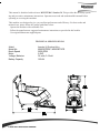
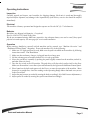
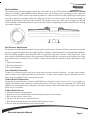
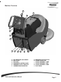
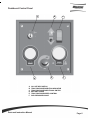
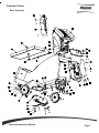
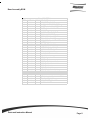
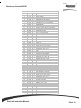
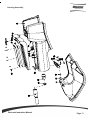
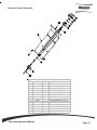
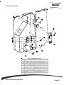
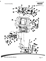
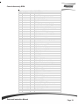
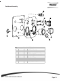
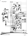
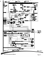
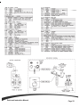
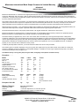
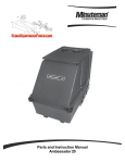
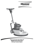
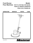
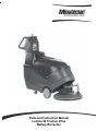
Parts and Instruction Manual
Lumina 20 Traction Drive
Battery Burnisher
This manual is furnished with each new MINUTEMAN Lumina 20. This provides the necessary operating and preventive maintenance instructions. Operators must read and understand this manual before
operating or servicing this machine.
This machine was designed to give you excellent performance and efficiency. For best results and
minimal cost, please follow the general guidelines below:
· Operate the machine with reasonable care.
· Follow the manufacturers suggested maintenance instructions as provided in this booklet.
· Use original Minuteman supplied parts.
TECHNICAL SPECIFICATIONS
Model
Model No.
Brush Speed
Motor
Voltage, Batteries
Battery Capacity
Parts and Instruction Manual
Lumina 20 Traction Drive
M26036TDQP / M26036TDCE
2600 RPM
2.5HP
36 volts, 3-12volt
165 AH
Parts and Instruction Manual
Table of Contents
IMPORTANT SAFETY INSTRUCTIONS .............................................................................................. 1
Operating Instructions ....................................................................................................................... 2
Inspection ........................................................................................................................................ 2
Electrical .......................................................................................................................................... 2
Batteries .......................................................................................................................................... 2
Operation ........................................................................................................................................ 2
After Use ......................................................................................................................................... 3
Maintenance .................................................................................................................................... 3
Floor Seal Strip ................................................................................................................................ 3
Battery Service and Installation ....................................................................................................... 3
Charging of Batteries ...................................................................................................................... 3
Battery Cable Routing ..................................................................................................................... 3
Pad Installation ................................................................................................................................ 4
Pad Pressure Adjustments .............................................................................................................. 4
Circuit Breaker Protection ............................................................................................................... 4
Carbon Brush Replacement ............................................................................................................ 4
Carbon Brush Service ..................................................................................................................... 4
Machine Overview .............................................................................................................................. 5
Dashboard Control Panel................................................................................................................... 6
Exploded Views .................................................................................................................................. 7
Base Assembly ................................................................................................................................ 7
Base Assembly BOM ...................................................................................................................... 8
Mainframe Assembly ....................................................................................................................... 9
Mainframe Assembly BOM ............................................................................................................ 10
Housing Assembly ......................................................................................................................... 11
Housing Assembly BOM ............................................................................................................... 12
Pad Driver Assembly ..................................................................................................................... 13
Pad Driver Assembly BOM ............................................................................................................ 14
Pressure Control Assembly ........................................................................................................... 15
Electrical Assembly ....................................................................................................................... 16
Console Assembly ......................................................................................................................... 17
Console Assembly BOM ............................................................................................................... 18
Dashboard Assembly .................................................................................................................... 19
Wiring Diagram ................................................................................................................................. 20
Minuteman International Made Simple Commercial Limited Warranty ........................................ 23
Parts and Instruction Manual
IMPORTANT SAFETY INSTRUCTIONS
CAUTION: Operators must read and understand this manual before operating or maintaining this
machine.
Keep hands and feet clear of moving parts while machine is in operation.
Disconnect the power to the machine by pressing the Red Emergency Disconnect Button when
charging batteries or during installation or removal of pads.
During operation, loose objects on the floor can become dangerous projectiles if struck by the high
speed pad. Special attention should be paid in removing or avoiding loose floor tile, electrical cables
and telephone connection boxes.
Electrical motors and components can cause an explosion when operated near explosive materials
or vapors. Do not operate this machine near flammable materials such as solvents, thinners, fuels,
grain dust, etc.
Keep machine moving to reduce the risk of damaging floor finish and floor.
Make sure the Red Emergency Disconnect Button is pressed and the battery connector is unplugged
from the machine before performing any maintenance procedures.
Store or park this machine on a level surface only.
These machines are designed for level floor operation only. Do not operate on ramps or inclines.
Battery acid can cause burns. When working on or around batteries, wear protective clothing and
safety glasses. Remove metal jewelry. Do not lay tools or metal objects on top of batteries.
Charging batteries generates explosive gases. DO NOT CHARGE BATTERIES WHEN OPEN
FLAMES OR SPARKS ARE PRESENT. DO NOT SMOKE. Make sure the charger is turned off
before disconnecting it from the machine. Charge the batteries in a well-ventilated area with the
battery cover removed completely.
Maintenance and repairs must be performed by authorized personnel.
SAVE THESE INSTRUCTIONS
Parts and Instruction Manual
Page 1
Operating Instructions
Inspection
Carefully unpack and inspect your burnisher for shipping damage. Each unit is tested and thoroughly
inspected before shipment; any damage is the responsibility of the delivery carrier who should be notified
immediately.
Electrical
This machine is battery operated and designed to operate on 36 volts DC (3) 12 volt batteries.
Batteries
Burnishers are shipped with batteries. (3 required)
Part No. 956210 12V 210AH 20 Hr. Rate
We do not recommend mixing AMP hour capacities. Any alternate battery sets can be used if they equal
physical size and capacity. See next page for service and installation.
Operation
Before starting, familiarize yourself with the machine and its controls (see “Machine Overview” and
“Dashboard Control Panel” diagrams). To turn the machine ON, do the following:
1. Make sure 20" high speed pad is used. Make sure the pad is installed on the machine by following
instructions under “Pad Installation.”
2. Make sure that no battery charger is plugged into the recharge port.
3. Lift the red emergency disconnect button so it is in the up position.
4. Lower the pad driver assembly by pushing the pedal slightly outward on the machine (unlock it),
and then release it slowly.
5. Turn the key switch to the ON position. The pad driver will then slowly adjust itself to the floor.
Make sure the machine is set to move forward indicated by the light on the dashboard control panel.
6. Place hands on the bails and squeeze the bail levers to start the operation of the machine. Move
forward in a straight line, check the reading on the Operating Range Meter and make sure you are
in the Green Zone.
7. Adjust the pad pressure as needed by turning the knob accordingly. (See Pad Pressure Adjustments.)
8. Adjust speed as needed by turning the speed control knob accordingly.
Parts and Instruction Manual
Page 2
After Use
To raise the pad driver, push down until the pedal arm engages into the pedal catch. Turn machine off by
turning the key switch on the control panel. Machine can be cleaned with a mild detergent and a damp cloth.
Batteries should be charged after each use or when the battery condition meter shows a low charge. Once the
battery charger reads 0 amps, the batteries are recharged. This should take approximately 8 hours if the
batteries are completely discharged.
Maintenance
Periodically remove batteries from machine. Clean the batteries and battery tray with a solution of baking
soda and water. Check all battery cables and wiring for signs of damage and wear. Replace as needed.
Grease front wheel and rear caster zerks once a month for best operation.
Floor Seal Strip
When the floor seal strip show signs of excessive wear, seal should be replaced. The strip can be removed by
loosening the screw on the retainer strap until the seal can slide off of the pad shroud housing. To install new
seal, slip the retainer strap over the new seal strip and pad shroud. Make sure the seal is seated equally
around the perimeter and the holes on the floor seal are oriented towards the back portion of the shroud.
Battery Service and Installation
WARNING: Battery acid can cause burns. When working on or around batteries, wear protective clothing
and safety glasses. Remove metal jewelry. Do not lay tools or metal objects on top of batteries.
Charging of Batteries
Charging batteries generates explosive gasses. DO NOT CHARGE BATTERIES WHEN OPEN FLAMES OR
SPARKS ARE PRESENT. DO NOT SMOKE. Make sure the charger is turned off before disconnecting it from
the batteries. Charge the batteries in a well-ventilated area with battery cover removed completely. Fluid
levels should be checked before and after charging and maintained at the proper levels. If the burnisher is not
used for extended periods of time, batteries should be kept fully charged with a boost charge once a week.
Battery Cable Routing
Parts and Instruction Manual
Page 3
Pad Installation
The red emergency disconnect button and the key switch must be in the OFF position before installation and the
pad driver assembly in the RAISED position. Remove center cup locking device by gripping on outer edges and
turning clockwise. NOTE: Center cup cannot be pulled out; it must be unscrewed. After removing used pad, place
new pad on pad driver assembly using outer flange of pad driver to center the pad. Push centering locking cup
through the pad and into the pad driver assembly. The ratchet teeth on the center cup will engage into the pad
driver assembly and should be pushed in as far as possible. If further tightening is needed, rotate the center-locking
cup counter-clockwise
Pad Pressure Adjustments
The pad pressure adjust knob is located on the top of the control console. Counter-clockwise rotation increases pad
pressure, the opposite rotation decreases. Different floors, conditions, and pads produce carrying pad load conditions.
Ideal burnishing conditions are maintained while the operating range meter remains in the Green Zone. If the
meter reads in the Red Zone decrease the pad pressure. When the machine is operated in the Red Zone for a long
period of time motor overload will occur and the 70-amp circuit breaker for the motor will trip. If the motor circuit
trips:
1. Check pad condition.
2. Decrease pad pressure.
3. Reset circuit breaker.
Circuit Breaker Protection
70 amp circuit breaker protects pad driver motor from excessive overload conditions. 3.0 amp circuit breaker
protects control circuits against possible electrical shorts. If either circuit breaker trips, first determine the cause
and correct the condition before resetting the breakers.
Carbon Brush Replacement
Design life of carbon brushes is between 1800-2000 hours. Replace brushes if worn to 3/8" or less, broken, or
chipped. All carbon brushes should be replaced when motor is serviced. Four (4) are required, P/N 572003. Red
indicator on control panel (above Emergency Disconnect Button, below the Dashboard) will glow when carbon
brush service is required.
Carbon Brush Service
1. Disconnect batteries from machine.
2. Remove two screws that hold dust control housing and motor cover to motor.
3. Blow out top of motor with air line.
4. Loosen screw and remove carbon brush lead.
5. Slide brush spring off the back of carbon brush and remove brush.
6. Reverse order for installation of new carbon brushes.
Parts and Instruction Manual
Page 4
Machine Overview
A
C
B
D
E
F
G
H
A
B
C
D
E
F
I
J
K
L
PAD PRESSURE ADJUSTMENT
BAIL LEVER
DUST BAG
DASHBOARD CONTROL PANEL
EMERGENCY BELLY BAR STOP
CARBON BRUSH INDICATOR
Parts and Instruction Manual
G
H
I
J
K
L
EMERGENCY STOP BUTTON
POWER CONNECTOR
CIRCUIT BREAKER, 70 AMP
CIRCUIT BREAKER, 3 AMP
CIRCUIT BREAKER, 18 AMP
FOOT PEDAL
Page 5
Dashboard Control Panel
A
D
A
B
C
D
E
F
B
E
C
F
ON / OFF KEY SWITCH
TRACTION DRIVE DIRECTION INDICATOR
TRACTION DRIVE DIRECTIONAL SWITCH
BATTERY GUAGE
TRACTION DRIVE SPEED CONTROL
PAD PRESSURE GUAGE
Parts and Instruction Manual
Page 6
Exploded Views
Base Assembly
Parts and Instruction Manual
Page 7
Base Assembly BOM
BILL OF MATERIAL
ITEM PART NO. REQ'D DESCRIPTION
1
200126
2
MOUNT, TRANSAXLE
2
200154
1
PANEL COVER WELDMENT
3
172167
2
CASTER, 3-1/2 POLYURETHANE
4
210141
2
WHEEL 8 X 1.5 X .75 BORE
5
260224
1
18" HOSE
6
260536
1
BASE PLATE WELDMENT
7
260541
1
REAR HANDLE BRKT
8
260549
1
PRESSURE ADJ ASSEMBLY
9
260579
1
TOOL CLIP, 1.5" HOSE
10
260583-1
1
CONSOLE ASY, 2600TD SPE BAT GA
11
260604
1
BATTERY BOX
12
260676
2
SPACER, TRANSAXLE
13
320271
1
NOZZLE BODY-ELBOW
14
320272
2
NOZZLE BODY LOCKNUT
15
320273
1
HOSE SHUT-OFF CLAMP
16
361233
2
KEY, 3/16 SQ. X 1.50"
17
711124
6
PAN HEAD ST #10 X .37 NI
18
711160
11 #10 X 5/8 HI-LO
19
711229
4
BLT-HH 5/16-18 x .875
20
711505
23 WSR-FLAT 1/4
21
711507
4
WSR-FLAT .37 X 1.12 X .06
22
711519
10 WSR- FLAT .25 X 1.01 X .06
23
711544
27 WSR-HELICAL 1/4
24
711545
4
WSR-HELICAL 5/16
25
712042
2
BLT-WSR HH 5/16-18 X .62
26
712318
4
WSR- FLAT.75 X 1.12 X .12 PL
27
712565
6
SCR-MC 1/4-20X.63 SS TR HD
28
712759
2
WSR- FLT .31 X 1.37 X .06 SS
29
713002
27 BLT-HH 1/4-20 UNC-2A X 3/4 STL#5
30
743800
1
TRANSAXLE 36VDC
31
743831
1
BURN ELECTRICAL ASSY
32 200102MCH
1
BASE MACHINED
Parts and Instruction Manual
Page 8
Mainframe Assembly
Parts and Instruction Manual
Page 9
Mainframe Assembly BOM
BILL OF MATERIAL
ITEM NO. PART NO. QTY. DESCRIPTION
1
260536
1 BASE PLATE W ELDMENT
2
260577-1
1 SW ITCH INTERLOCK BRACKET
3
711503
2 W SR, FLAT#10
4
711350
2 NUT NYLOC 10-32
5
740830
1 SW ITCH SPST NC CONTACT
6
711501
2 W SR-FLAT # 6
7
710307
2 SCR-MC 6-32 X 1.0 ST PL PAN HD
8
711430
1 NUT-TINNERMAN TW IN 6-32
9
260522
1 SPRING GUIDE
10
670605
2 ROLLER PIN
11
711506
8 W SR-FLT .344 X .690 X .062 STL ZINC
12
711721
4 RET RING-E TYPE .312
13
260524
2 ADJUSTMENT LINK
14
711515
2 W SR-FLAT .406 X .812 X .0625
15
831965
1 3/8 x 1.63" CLEVIS PIN
16
711808
1 COTTER PIN-HAIR #13
17
260511
1 UPPER W MT
18
260521
1 GUIDE TUBE
19
711511
1 W SR-FLAT .62 X 1.31 X .09
20
762339
1 SPRING COMPRESSION
21
260523
1 SPRING SPACER 1.50 X .632 X .84
22
260519
2 PIVOT PIN
23
711592
2 W SR-FLAT .50 X .9 X .075 NYL
24
712310
19 W SR- FLAT .52 X .87 X .06 PL
25
711713
6 RETAINING RING - "E" TYPE EXT .500
26
711524
6 W SR-W AVE .52 X .87 X .01
27
260576
1 LINK
28
260528
1 LINK
29
260529
2 TRAILING LINK
30
260513
1 MOTOR LIFT W ELDMENT
31
712102
1 BLT- SHLDR 1/2 X 1-1/2
32
712301
1 W SR-FLAT .87 X .38 X .06
33
711380
1 NUT-NYLOC 3/8-16 NUT
34
743598
1 TERMINAL BLOCK, 2 POS
35
710036
1 SCR-MC 8-32 X 1.50 ST PL
36
711372
1 NUT-NYLOC 8-32 STL ZINC
37
210142
1 PEDAL PAD
38
260586
1 SUPPORT, BATTERY LOW ER
39
260587
1 SUPPORT, BATTERY UPPER
40
712139
4 SCR-TR 1/4-20X 1.00 HW H
41
711229
4 BLT-HH 5/16-18 x .875
42
260615
1 MOTOR PLATE W ELDMENT - NEW
43
708
1 RTV SILICONE 10 OZ TUBE
44
260519
2 PIVOT PIN
45
712310
12 W SR- FLAT .52 X .87 X .06 PL
46
711713
5 RETAINING RING - "E" TYPE EXT .500
47
711524
2 W SR-W AVE .52 X .87 X .01
48
260525
1 ADJUSTMENT NUT
49
712905
1 NUT-HEX 10-24 NIPL
50
711717
2 RETAINING RING- E TYPE .37
51
743644
1 DIN RAIL, CUT - 2.00"
52
711503
2 W SR, FLAT#10
53
711543
2 W SR - HELICAL #10
54
710356
2 SCR-MC 10-32X.62 STPL
55
743640
1 TERMINAL BLOCK, RED (SPRING TYPE)
56
743641
1 TERMINAL BLOCK, BLACK (SPRING TYPE)
57
743642
1 TERM BLOCK, END PLATE
58
743643
2 TERM BLOCK, ANCHOR
Parts and Instruction Manual
Page 10
Housing Assembly
Parts and Instruction Manual
Page 11
Housing Assembly BOM
ITEM
1
2
3
4
5
6
7
8
9
10
11
12
13
14
15
16
17
18
19
20
21
22
PART NO.
260501
260502
260503
260504
260560
260590
260592
260596
310008
450037
450081
450207
710180
711160
711228
711373
711374
711506
711516
711519
828970
831001
Parts and Instruction Manual
BILL OF MATERIAL
REQ'D DESCRIPTION
1
FIXED TOP COVER
1
MOVING TOP COVER
1
BAG COVER
1
FILTER COVER WELDMENT
1
HINGE 9.75"
1
HOSE ASSY DUST CONTROL
1
EXHAUST FILTER DUST CONTROL
1
INSERT FITTING, 1-1/2"PVC, FPT
1
O RING BUNA 2201510561
1
ADAPTER MACHINED
1
WSR-SS 1.908 x 2.41 x .03
1
LATCH, SOFT #C7-10
3
SCR-MC TR HD 1/4-20x.75 STL ZINC
10
#10 X 5/8 HI-LO
4
BLT-HH 5/16-18 X .75 ST PL
3
NUT-NYLOC 1/4-20
4
NUT-NYLOC 5/16-18
4
WSR-FLT .344 X .690 X .062 STL ZINC
4
WSR- FLAT .31 X 1.25 X .05
3
WSR- FLAT .25 X 1.01 X .06
1
WSR-NEOP 1.87 X 2.4 X .125
1
CRIMP CLAMP, 440R
Page 12
Pad Driver Assembly
Parts and Instruction Manual
Page 13
Pad Driver Assembly BOM
BILL OF MATERIAL - 260610
ITEM PART NO. REQ'D
DESCRIPTION
1
260573
1
MOTOR GRILL ASSY
2
260597
1
KEY, 3/16 X .906
3
260611
1
PAD DRIVER SHROUD - 20"
4
260615
1
MOTOR PLATE WELDMENT - NEW
5
260616
1
DUST SKIRT - NEW
6
260619
2
PAD DRIVER STRAP
7
670075
1
PAD DRIVER ASSY
8
710857
1
SCR-SC 5/16-24 X 1.00
9
711124
2
PAN HEAD ST #10 X .37 NI
10
711505
3
WSR-FLAT 1/4
11
711512
4
WSR-FLAT .75X1.37X.08
12
711516
1
WSR- FLAT .31 X 1.25 X .05
13
711544
7
WSR-HELICAL 1/4
14
711545
1
WSR-HELICAL 5/16
15
712070
4
BLT, SHLDR 5/16 X .75
16
712537
14 10-24 X .75 SS TRUSS HD SCR
17
713003
3
BLT-HH 1/4-20 X 1 #5
18
760401
1
CENTER CUP, NEW STYLE
19
809857
4
TRIGGER SPRING
20 260581MCH
1
GRABBER RING, MACHINED
21
742461-2
1
MOTOR 66 FRAME 36V HI SPD
Parts and Instruction Manual
Page 14
Pressure Control Assembly
ITEM
1
2
3
4
5
6
7
8
9
10
11
12
13
14
BILL OF MATERIAL - 260549
PART NO. REQ'D DESCRIPTION
260066
1
OILITE BUSHING
260547
1
PRESS ADJ MOUNT WELD
260554
1
PRESS ADJ SCREW
260557
1
PRESS ADJ SLIDE
260562
1
PRESS ADJ RET BRKT
260563
1
PRESS ADJ RET BRKT
260564
1
ROLL PIN 3/16"X3/4"
710353
4
SCR-MC 10-32 X .37 ST PL
711391
1
NUT-HEX JAM 3/8-16 ST PL
712536
1
SCR-MC 10-24 X .62 TH SS
715038
1
DECAL, PAD PRESSURE
760034
1
KNOB, ADJ (SET SCREW)
762253
1
CABLE, ASSY PRESSURE
833102
1
SPRING, .62 X .75 X 1.75
Parts and Instruction Manual
Page 15
Electrical Assembly
BILL O F M ATERIAL - 260588
IT EM P ART NO . REQ 'D DES CRIP TIO N
1
260542
1
B A CK P A NE L W E LDM E NT
2
710356
2
S CR-M C 10-32X. 62 S TP L
3
711425
2
NUT, HE X 1/4-20 W IZNUT
4
740131
1
CIRCUIT B RE A K E R - 70A M P
5
740132
2
INS ULA TO R, P LA S TIC
6
740238
1
CIRCUIT B RE A K E R - 18A
7
740243
1
CO NTA CTO R 36V 124-117111
8
742749
1
HE Y CO , HO LE P LUG
9
743464
1
S HUNT CA LIB RA TE D A S S Y
10
746006
1
CIRCUIT B RE A K E R - 3A
11
833638
2
B RA S S S TUD
Parts and Instruction Manual
Page 16
Console Assembly
Parts and Instruction Manual
Page 17
Console Assembly BOM
ITEM
1
2
3
4
5
6
7
8
9
10
11
12
13
14
15
16
17
18
19
20
21
22
23
24
25
26
27
28
29
30
31
32
33
34
35
36
37
38
39
40
41
42
43
44
45
46
BILL OF MATERIAL - 260583-1
PART NO. REQ'D DESCRIPTION
200039
1
BAIL STOP RH
200040
1
BAIL STOP LH
200184
1
SWITCH BRACKET WELDMENT
200338
2
CAM WELDMENT
200340
2
SPACER, SCR BOARD
220324
2
SPRING
260538
1
FRONT BRKT HANDLE WELDMT
260584-1
1
DASHBOARD ASY, SPE BATTERY GAUGE
260589
1
PANEL, LUMINA 20 E-STOP
260605
1
LUMINA 20"ANDERSON PLUG BRK'T
670093
1
SPRING, COMPRESSION
710178
2
SCR-MC 1/4-20 X .50 TRUSS STPL
710180
2
SCR-MC TR HD 1/4-20x.75 STL ZINC
710195
6
SCR-MC 5/16-18 X .50
710207
6
SCR-MC 6-32 X .87 ZINC
710534
2
SCR-MC TR HD 8-32 X 1.00 SS
711004
2
SK-CUP PT 1/4-20 X .25 STL BLACK
711160
8
#10 X 5/8 HI-LO
711210
2
BLT-HH 1/4-20 X 1.25 STPL
711310
1
NUT, HEX 10-32 ST PL
711372
2
NUT-NYLOC 8-32 STL ZINC
711425
3
NUT, HEX 1/4-20 WIZNUT
711430
3
NUT-TINNERMAN TWIN 6-32
711505
2
WSR-FLAT 1/4
711534
1
WSR-EXTERNAL LOCK #10
711544
4
WSR-HELICAL 1/4
711721
6
RET RING-E TYPE .312
712540
8
SCR-MC TR HD 10-24 X .37 SS
712569
1
SCR-MC TR HD 1/4-20 X 1.50 SS
713002
2
BLT-HH 1/4-20 UNC-2A X 3/4 STL#5
715589
1
DECAL, PANEL COVER
740147
1
CB 175 GRAY HOUSING
740803-1
1
SPEED CONTROL 36V 1203A-304
740946
1
POTENTIOMETER 5K
740029
1
EMERGENCY STOP SWITCH
742472
1
SWITCH
743832
1
WIRE ASSEMBLY
743966
1
WIRE ASY, GREEN/YELLOW 16G
747016-1
1
LED ASSY RED
805637
1
SCR INSULATOR
809874
1
KNOB, SPEED CONTROL
829052
4
BUSHING FLANGED NYLON .312 ID
200104MCH
1
HANDLE CONSOLE 200
200181CTD
2
HANDLE WIRE COATED
200190CTD
1
LEVER, SWITCH
833329SA
2
SWITCH, DPDT STAGGERED ACTION
Parts and Instruction Manual
Page 18
Dashboard Assembly
ITEM
1
2
3
4
5
6
7
8
9
10
BILL OF MATERIAL - 743830-1
PART NO. REQ'D DESCRIPTION
260506-1
1
PLATE, DASHBOARD
715440
1
DECAL, DASHBOARD
740135
1
METER, 100A DC (PRESSURE)
740946
1
POTENTIOMETER 5K
746103
1
GAUGE, BATTERY/HOUR W/RELAY
747016-1
1
LED ASSY RED
747017-1
1
LED ASSY AMBER
747024
1
KEYSWITCH, SPST ES2832 SOLDER
748151
1
SWITCH, ON-ON, DPDT
809874
1
KNOB, SPEED CONTROL
Parts and Instruction Manual
Page 19
Wiring Diagram
Parts and Instruction Manual
Page 20
Parts and Instruction Manual
Page 21
Parts and Instruction Manual
Page 22
Minuteman International Made Simple Commercial Limited Warranty
REVISION F
EFFECTIVE 6/1/2009
Minuteman International, Inc. warrants to the original purchaser/user that the product is free from defects in workmanship and materials under
normal use. Minuteman will, at its option, repair or replace without charge, parts that fail under normal use and service when operated and
maintained in accordance with the applicable operation and instruction manuals. All warranty claims must be submitted through and approved
by factory authorized repair stations.
This warranty does not apply to normal wear, or to items whose life is dependent on their use and care, such as belts, cords, switches, hoses,
rubber parts, electrical motor components or adjustments. Parts manufactured by Minuteman are covered by and subject to the warranties
and/or guarantees of their manufacturers. Please contact Minuteman for procedures in warranty claims against these manufacturers.
Special warning to purchaser — Use of replacement filters and/or prefilters not manufactured by Minuteman or its designated licensees, will
void all warranties expressed or implied. A potential health hazard exists without original equipment replacement.
All warranted items become the sole property of Minuteman or its original manufacturer, whichever the case may be.
Minuteman disclaims any implied warranty, including the warranty of merchantability and the warranty of fitness for a particular purpose.
Minuteman assumes no responsibility for any special, incidental or consequential damages.
This limited warranty is applicable only in the U.S.A. and Canada, and is extended only to the original user/purchaser of this product.
Customers outside the U.S.A. and Canada should contact their local distributor for export warranty policies. Minuteman is not responsible for
costs or repairs performed by persons other than those specifically authorized by Minuteman. This warranty does not apply to damage from
transportation, alterations by unauthorized persons, misuse or abuse of the equipment, use of non-compatible chemicals, or damage to
property, or loss of income due to malfunctions of the product.
If a difficulty develops with this machine, you should contact the dealer from whom it was purchased.
This warranty gives you specific legal rights, and you may have other rights which vary from state to state. Some states do not allow the
exclusion or limitation of special, incidental or consequential damages, or limitations on how long an implied warranty lasts, so the above
exclusions and limitations may not apply to you.
Cord Electric Group: Three years parts, two years labor, ninety days travel (Not to exceed two hours)
Exceptions……….
Model
Parts
Labor
Poly
Travel
Port A Scrub
MPV 13
MPV 14 & 18
V Series Upright Vacuums
Rapid Air Blower
Explosion Proof Vacuum
X12, X12H & TRS 14
E17 & E20 Electric Scrubbers
1yr
1yr
2yrs
1yr
1yr
1yr
1yr
1yr
6months
0
1yr
1yr
1yr
1yr
1yr
6month
10yrs
0
0
0
10yrs
0
10yrs
10yrs
0
0
0
0
0
0
0
0
Pneumatic Vacuums
3yr
1yr
0
0
Description
Parts
Labor
Poly
Travel
Battery Operated Group
Sweepers
Internal Combustion Group
3yrs
1yr
1yr
2yrs
1yr
1yr
10
10
10
90 days
90 days
90 days
Not to exceed two hours
Exception: PAS 14B
1yr
Battery Chargers:
One year replacement
Ninety days
0-3 months replacement, 4-12 months pro-rate
Tanks have 10yr warranty, no additional labor
Replacement Parts:
Batteries:
Polyethylene Plastic Tanks:
1yr
10yr
0
14N845 U.S. Route 20, Pingree Grove, IL 60140 USA
Phone (800) 323-9420 - www.minutemanintl.com
A Member of the Hako Group
988172
Rev F 0410