1
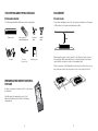
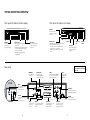
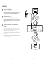
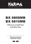
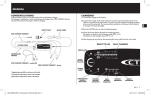
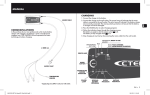
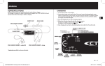
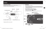
INSTALLATION MANUAL VIP 1903 / VIP 1903 T VIP 1963 / VIP 1963 T Caring for the Environment by Recycling WARNING When you see this symbol on a Motorola product, do not dispose of the product with residential or commercial waste. TO REDUCE THE RISK OF FIRE OR ELECTRICAL SHOCK, DO NOT EXPOSE THIS APPLIANCE TO RAIN OR MOISTURE. Recycling your Motorola Equipment IMPORTANT SAFETY INSTRUCTIONS Please do not dispose of this product with your residential or commercial waste. Some countries or regions, such as the European Union, have set up systems to collect and recycle electrical and electronic waste items. Contact your local authorities for information about practices established for your region. If collection systems are not available, call Motorola Customer Service for assistance. • Read these instructions. • Keep these instructions. • Heed all warnings. • Follow all instructions. • Do not use this apparatus near water. Please recycle this document. • Clean only with dry cloth. • Install in accordance with the manufacturer’s instructions. • Do not install near any heat sources such as radiators, heat registers, stoves, or other apparatus (including amplifiers) that produce heat. • Battery pack or batteries installed shall not be exposed to excessive heat such as sunshine, fire or the like. • • o not defeat the safety purpose of the poD larized or grounding-type plug. If the provided plug does not fit into your outlet, consult an electrician for replacement of the obsolete outlet. o naked flame sources, such as lighted N candles, should be placed near the apparatus. • Protect the power cord from being walked on or pinched, particularly at plugs, convenience receptacles, and the point where they exit from the apparatus. o not expose the power supply to dripping D or splashing and do not place objects filled with liquids, such as vases, on the power supply. • nsure that the mains plug remains readily E operable. Declaration of Conformity We Motorola Mobility, Inc. 101 Tournament Drive Horsham Pennsylvania 19044 USA declare under our sole responsibility that the product to which this declaration relates are in conformity with the following directives: EMC Directive 2004/108/EC Low Voltage Directive 2006/95/EC WEEE Directive 2002/96/EC RoHS Directive 2002/95/EC • • se only attachments and accessories speciU fied by the manufacturer. • nplug this apparatus during lightning storms U or when unused for long periods of time. • efer all servicing to qualified service personR nel. Servicing is required when the apparatus has been damaged in any way, such as when the power-supply cord or plug is damaged, liquid has been spilled or objects have fallen into the apparatus, the apparatus has been exposed to rain or moisture, does not operate normally, or has been dropped. POWER SUPPLY • Keep distances around the power supply for sufficient ventilation. CAUTION TO PREVENT ELECTRICAL SHOCK, DO NOT USE THIS PLUG WITH AN EXTENSION CORD, RECEPTACLE, OR OTHER OUTLET UNLESS THE BLADES CAN BE FULLY INSERTED TO PREVENT BLADE EXPOSURE. according to the following standards: EN55013 (VIP1903T, VIP1963T) EN55020 (VIP1903T, VIP1963T) EN55022 (VIP1903, VIP1963) EN55024 (VIP1903, VIP1963) EN60065 The lightning flash with arrowhead within an equilateral triangle is intended to alert the user to the presence of uninsulated dangerous voltage within the product’s enclosure that may be of sufficient magnitude to constitute a risk of electric shock. The exclamation point within an equilateral triangle is intended to alert the user to the presence of important operating and maintenance (servicing) instructions in the literature accompanying the product. Repairs If you find the unit in need of repair, contact your system operator for repair or replacement. 2 3 YOUR VIP1903 AND VIP1963 PACKAGE PLACEMENT Enclosed material Do not cover The following material should be present in your package. Do not place anything on top of the set-top box, instead leave a free space of 20 cm above it for proper ventilation and cooling. IP set-top box AC adaptor Remote control with 2 AAA batteries RF cable (T models only) Ethernet cable Installation guide SCART cable When using the remote control, point it to the IR-receiver in the center of the front panel. Make sure that there is no obstacle between the remote control and the set-top box, such as for example a table. For best reception of the IR-signals from the remote control to the set-top box, make sure to place the set-top box close to the edge of the shelf. PREPARING THE REMOTE CONTROL FOR USE In order to prepare your remote control for use, insert the batteries. Carefully place the terminals (+ and -) of the batteries as indicated on the back of the battery compartment. 4 5 VIP1903 AND VIP1963 OVERVIEW Front panel of models without display Front panel of models with display REC LED (On VIP1963 only) Indicates an on-going recording REC LED (on VIP1963 only) Indicates an on-going recording Indicator LED:s • Green light - the set-top box is operational. • Flashing green light - the set-top box receives a signal from the remote control or a keyboard. • Red light - the set-top box is in stand-by mode. IR receiver Receives signals from remote control and keyboard. Indicator LED • Green light - the set-top box is operational. • Flashing red/green light - the set-top box receives a signal from the remote control or a keyboard. • Red light - the set-top box is in stand-by mode. Display Standby switch IR receiver Receives signals from remote control and keyboard. The marking plate is located on the exterior of the bottom of the unit. Rear panel ETHERNET for broadband connection VIP1963 Navigation keys SCART (VCR) for connection to additional equipment such as VCR or DVD YPbPr (Component video) for �������� connection to TV set (analog High Definition video SPDIF for connection to digital audio equipment RF IN for connection to digital cable television. On T models only. RF OUT for loop through of the RF signal. On T models only. 6 TOSLINK for optical connection to digital audio equipment POWER for connection of external power supply USB for connection to external devices. HDMI for connection to TV set (digital High Definition video) SCART (TV) for connection to TV set (analog Standard Definition video) AUDIO L/R for connection to HiFi equipment or TV set (analog stereo audio) 7 INSTALLING Connecting to broadband Optional: VCR or DVD recorder Connect one end of the Ethernet cable to the connector marked ETHERNET on the rear panel of the set-top box and the other end to a hub or the Ethernet wall connector provided by your broadband operator. Connecting to the TV set Connect one end of the enclosed SCART cable to the SCART connector marked TV on the set-top box and the other end to your TV set. Both analog audio and standard definition video are sent to the TV set through this connection. Broadband wall outlet or hub Optional: Connecting to a VCR or digital video recorder You can record the program you are currently watching by connecting an auxiliary device, such as a VCR or a digital video recorder, to the set-top box, provided that the program is copy-approved content. Connect the set-top box to the auxiliary device using the SCART connector marked “VCR”. To record, change to the TV channel on the set-top box you wish to record and start recording on the device. TV 8 9 OPTIONAL: CONNECTING HIGH DEFINITION VIDEO If your TV set is HDTV compatible, you can connect the set-top box to the TV set using the HDMI or the component connectors instead of the SCART connector to receive and display HDTV, i.e. skip installation step and replace it with installation step or . Using the HDMI connector OPTIONAL: CONNECTING TO EXTERNAL AUDIO If you want to use an external source to play audio such as a stereo or home cinema equipment or if you are using the component connectors to connect the set-top box to the TV set, there are three possible methods of connecting to audio. Analog stereo: Using the Audio L/R connectors If your TV set has a HDMI connector, you can connect it to the HDMI connector on the set-top box with a HDMI cable (not included) to receive digital high definition video and digital audio. Connect a dual RCA cable (not included) to the Audio L/R connectors on the set-top box and connect the other ends to your stereo or TV set. Make sure to match the connectors so that L on the set-top box (white) is connected to L on the TV set or stereo and R is connected to R. Using the component connectors (YPbPr) Digital audio: Using the SPDIF connector If your TV set has a component video connectors (YPbPr), you can connect it to the component connectors on the set-top box with three RCA cables (not included) to receive analog high definition video. Connect an RCA cable (not included) to the SPDIF connector on the set-top box and connect the other end to your stereo or TV set. Make sure to match the connectors so that Y on the set-top box is connected to Y on the TV set, Pb to Pb and Pr to Pr. Connect a Toslink cable (not included) to the Toslink connector on the set-top box and connect the other end to your stereo or TV set. Digital audio: Using the optical Toslink connector Note! The component connectors only send video signals. To receive audio you also need to use one of the possible audio connections, i.e. step , or . Stereo/ HiFi system TV 10 11 CONNECTING TO TERRESTRIAL TV (MODEL T ONLY) Connecting to terrestrial TV Some models are prepared to receive digital terrestrial TV (VIP19x3T). CONNECTING TO POWER Connecting to power When all other cables are connected, connect the power cord to the power connector on the set-top box and to mains power. Connect one end of an RF cable to the RF-IN connector and the other end to the antenna outlet in your home. For information on how you proceed with the channel search and scanning, please see separate instructions from your operator. Digital TV outlet/Antenna NOTE: Do not use an AC adaptor other than the one that is supplied with the product. Doing so may cause fire or seriosly damage the set-top box. OPTIONAL ON SOME MODELS: INSERTING A SMARTCARD If you have received a smartcard to enable access to the TV signals, fully insert it in the smartcard slot on the side of the set-top box to make it in line with the casing. The chip on the smartcard should be directed downwards and towards the set-top box. 12 13 Displaying picture OPEN SOURCE SOFTWARE INFORMATION To display the signal from the set-top box on the TV set, switch to an external input. (On some TV sets this is done automatically.) There is often a button on the TV remote control for this purpose. Otherwise, see your TV User’s Guide for instructions. An example of what the input symbol may look like. For instructions on how to obtain a copy of any source code being made publicly available by Motorola related to software used in this Motorola set-top box you may send your request in writing to: The Motorola website opensource.motorola.com also contains information regarding Motorola’s use of open source. Motorola has created the opensource.motorola.com to serve as a portal for interaction with the software community-at-large. Motorola, Inc. OSS Management 2450 Walsh Avenue Santa Clara, CA 95051 USA To view additional information regarding licenses, acknowledgments and required copyright notices for open source packages used in this Motorola set-top box, please navigate to the Open Source Notices section in the user interface. NAVIGATING USING THE REMOTE CONTROL The navigation buttons (the inner ring comprised by four arrow buttons and an OK button) are used to move around on Service portal pages and in menus, and to select the highlighted alternative. The navigation buttons are also used to navigate web pages, as the buttons of the inner ring will move the indicator between the different links. Use the OK button to select links to be opened. The scroll buttons, the outer ring, are used when a web page contains more information than can be displayed on a TV screen. For information about the functionality of the other buttons on the remote control, please see the information provided by your IPTV provider. © 2011 Motorola Mobility, Inc. All rights reserved. No part of this publication may be reproduced in any form or by any means or used to make any derivative work (such as translation, transformation, or adaptation) without written permission from Motorola, Inc. MOTOROLA and the Stylized M logo are registered in the US Patent and Trademark Office. All other product or service names are the property of their respective owners. Motorola reserves the right to revise this publication and to make changes in content from time to time without obligation on the part of Motorola to provide notification of such revision or change. Motorola provides this guide without warranty of any kind, implied or expressed, including, but not limited to, the implied warranties of merchantability and fitness for a particular purpose. Motorola may make improvements or changes in the product(s) described in this manual at any time. This installation guide is produced by the manufacturer in the English language. Operators may elect to translate the installation guide. Any translated version of the installation guide is created purely for the convenience of the operator and end user and the English language version is controlling and shall prevail. Motorola hereby disclaims all liability for any translated versions of the installation guide created by an operator, for but not limited to, the content of any translated installation guide, the accuracy of the translation and any issues arising as a result of the translated installation guide, 14 15 STARTING UP When the set-top box is connected to the TV set, Ethernet and power, you will see an image similar to the one to the right on the TV screen. The set-top box is now connecting to the network and downloading the software needed. Please wait until the loading is finished. Five circles will indicate the download progress during the start up of the system. From the start, all circles are dark grey. As the set-top box searches for software or is processing downloaded software, one circle at a time starts blinkning yellow. When software is being downloaded, a progress bar of ten small dots appear and the corresponding circle blinks green. When each of the five steps in the start up process is completed, the corresponding circle turns green. When all circles are green, the system is ready to run. If the software in any of the steps could not be loaded, the circle representing this step turns red and remaining steps are cancelled. TROUBLE SHOOTING If you encounter any problems during start up, please note which of the circles (1 - 5) that has not turned green before you contact your support personnel. ON-LINE HELP When your set-top box is up and running, please see the instructions provided by your IPTV provider on how to reach the services and how to access the User’s Guide. Motorola Mobility, Inc. 101 Tournament Drive Horsham Pennsylvania 19044 USA http://www.motorola.