1
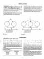
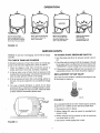
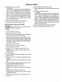
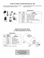
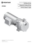
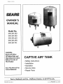
F642-9301
OWNER"
MA UAL
Model No.
390.291352
390.291552
390.291652
390.291690
390.291751
CAUTION:
Read and Follow
All Safety Rulesand
Operating Instructions
Before First Use of
This Product.
Save ThisManual For
Future Reference.
CAPTIVE AIR®TANK
• Safety Instructions
• Installation
• Operation
• Service Hints
. Repair Parts
Sears, Roebuck and Co., Hoffman
PRINTED
IN
USA
Estates, IL 60179
U.S.A.
Form No F642-9301
(Rev 9/20/95)
READ
AND
FOLLOW
SAFETY
INSTRUCTIONS!
This is the safety alert symbol.
When you see this symbol on your tank or in this manual,
look for one of the following
personal
signal words
injury:
and
be
alert
to the
potential
for
DANGER warns about hazards that will cause serious personal injury, death or major property damage if ignored.
WARNING
N,NGi
o,oT,oN
I
warns
rious personal
nored.
about
injury,
hazards
death
that will
or major
or can
property
cause
damage
seif ig-
CAUTION warns about hazards that will or can cause
minor personal injury or property damage if ignored.
The label NOTICE indicates special instructions
important but not related to hazards.
Carefully
read and follow
this manual and on tank.
all safety
which are
instructions
in
Keep safety labels in good condition.
Replace missing or damaged
RULES FOR SAFE INSTALLATION
safety labels.
AND OPERATION
1. Read these Rules and the Instructions carefully. Failure
to follow them could cause serious bodily injury and/or
property damage.
NOTICE:
Mthough
No. 27220 Relief Valve is set to open
at 75 PSI, for your safety Captive Air@ Tanks are designed
and rated to operate
at up to 100 PSI.
&WARNING These water storage tanks are designed for
Hazardous operation on cold well water systems lirapressure
ited to a maximum working pressure of 100
pounds per square inch (PSI). If your water system can exceed 100 P.S.I., install a Sears No. 27220 relief valve on the
system. Failure to follow these instructions can cause tank
blow-up and result in serious injury.
2.
Be sure installation
electrical
and well
meets
codes.
all local
plumbing,
pump,
3. Always test water from well for purity before using. Call
your local health department for testing procedure.
4. Before installing or servicing your pump,
pump power source is disconnected.
BE SURE
CONTENTS
W._NTY
...........
, .................
, ....
,, ....
INTRODUCTION
,, .............
,.o,..,
.....
SAFETY ............................................................................
2
INSTALLATION .............................................................
3-6
OPERATION ......................
:.............................................
7
SERVICE HINTS ............................................................
7-9
REPAIR PARTS ...........................................................
10-11
BASIC TOOLS
PLASTIC
Please read our instructions before you install and use your
tank. This will help you obtain full benefits from this tank.
It will also help you avoid needless service expense that
result from causes we cannot control and cannot cover in
our Wan-anty.
,.2
AND
HATERIALS
NEEDED
PIPE INSTALLATIONS
TOOLS
HATERIALS
Pipe Wrenches
Plastic Pipe and Fittings (as required
Screwdriver
Teflon Tape (DO NOT use pipe joint compound
Knife or Saw to Cut Plastic Pipe
plastic fittings) or Plasto-Joint
Tire Pressure
GALVANIZED
to complete
job).
on
Stik*
Gauge
STEEL PIPE INSTALLATIONS
HATERIALS
TOOLS
Pipe Wrenches
Galvanized
Screwdrivers
Pipe Joint Compound
Pipe Cutting and Threading
Tire Pressure
Pipe and Fittings (as required
to complete
job).
or Teflon tape
Tools
Gauge
INSTALLATION
,_kWARNING
Hazardous
pressure
of tank
ff your system can develop
more than 100
PSI pressure,
install a Sears No. 27220 relieve valve in system to prevent
possibility
blow-up.
NOTICE:
DO NOT use any type
water on Hose to Plastic fittings.
of lubricant
If rigid piping is installed
to support
the piping.
on inlet flange,
to elbow
other
than
BE SURE
For proper
installation
of your pump to tank, follow
of the typical installations
on Page 4 and 5. Use Teflon
on all threaded
connections
to tank.
one
tape
Standard pipe fittings, such as nipples, tees and elbows
must be purchased locally. If you are using a horizontal jet
pump mounted on top of tank, Figures 3, 4 and 5, Kit No.
2788 is required. See Page 10 for contents of kit.
If your present system has an air volume
move it and plug AVC port on pump.
control (AVC), re-
Complete pump, tank, and piping system MUST be protected against below freezing temperature.
Failure to do
so could cause severe damage and voids the warranty.
* lake Chemical
Co., Chicago, Illinois.
To Service
--To
Priming Tee .._= User,
.
......---__upp eo
Service
[
]
Typical installation on
Tank No. 390.291352,
To mount pump to tank,
order tank fittings Kit 2788.
FIGURE
FIGURE
IA
IB
i
1* - 1" x 3/4"
- 1" x 3/4"REDUCER BUSHING
UCER BUSHING
•Not Furnished - Must
Be Purchased Locally
2A - 2 Gallon Tank Hounted
FIGURE
Directly
Above Shallow Well
Above Convertible
FIGURE
3 - Tank With
FIGURE
Well
Pump
Pump
Shallow
FIGURE
4 - Tank With
Convertible
Pump
2B - 2 Gallon Tank Hounted
Pump
FIGURE 5 - Tank With
Hydroglass® Pump
INSTALLATION
NOTICE. 50 and 85 gallon tanks are
not equipped
with mounting
bracket.
Install pump beside tank as shown.
#
NOTICE. When using plastic fitting or
installing a plastic pump, use only
Teflon tape or Plasto-Joint Stik on male
threads.
1" - 1" x 1" Tee
2* - 1" Nipple
3* - 1-1/4" X 1" Reducer
Required
for 50 and 85
gallon
tanks.
Bushing
*Not furnishedmust be
purchased locally
To Service
Pump To Tank Fittings PackageNot Furnished
With Tank,
Order Kit Stock No. 2788
From Your Sears Store.
FIGURE
6 - 19, 36, 50 and 85 Gallon Tanks With
To Pump
Motor
Disconnect
Electrical
Box
50 GALLON**
85
Control
Centert
must
I __
IHigh capacity
pumps
not be used with tanks of less
than
50 gallon
I_WARNING
/
Relief Valve
Stock No.
27220
capacity.
** Tank furnished
with
I-I/4" to I" reducer
piping.
From
Well
Submersible Pump
Manifold Kit
Stock No. 27221
Pumps
TANK SIZES
19 GALLON
36 GALLON
To Service
T
Multi-Stage
1789 0595
elbow.
required
Note: Relief Valve (No. 27220)
be purchased
separately.
t Control
Pressure Gauge
Stock No. 2768
I-I/4"
pumps
Center
used with
for I"
must
3-wire
only.
For 2-wire pumps, connect
pressure
switch to disconnect
switch.
FIGURE
7-
Tanks With
Residential
High Capacity Or Residential Size Submersible Pumps
Series Pumps Use I" Piping. High Capacity Series Pumps
Use I-I/4"
Piping.
INSTALLATION
Captive Air® Tanks can be connected together to increase
the supply of usable water (drawdown).
Two tanks of the
same size will double the supply and three tanks will triple
the supply. See Figures 8 and 9 for typical installations.
IAWARNING If your system can develop
more than
Hazardous 100 PSI pressure,
install a Sears No.
pressure
27220 relieve valve in system
to prevent possibility
of tank blow-up.
NOTICE: All Captive Air® Tanks except Model 390.291352
are designed to operate in the vertical position.
When using a submersible pump, the manifold and switch
assembly must be installed in the pipe line as close to the
center of the tanks as possible. See Figures 8 and 9.
The tank is shipped from the factory with a pre-charge of
air. This system DOES NOT require the use of any outside
air charging devices such as air volume controls on jet
pumps, or bleeder orifices on submersible pumps.
Tanks
Tanks
I
From
Well
To
Service
Froml
Well '
I
I
I
I
To
Service
/
Pressure Switch and 27220
Relief Valve Location When
Pressure Switch end 27220
Using Submersible
Using Submersible
FIGURE
I
Relief Valve Location When
Pump
8
FIGURE
Pump
9
OPERATION
BEFORE
YOU
START YOUR
PUHP
Your tank is factory charged with forty (40) pounds of air
pressure. To determine pressure switch setting, see pump
owner's manual. If your pump pressure switch cut-in setting is less than forty (40) pounds, the tank air pressure
MUST be reduced to this cut-in pressure switch setting
(see table). To do this, bleed air from the valve located on
top of the tank. Check pressure frequently with an accurate tire pressure gauge until correct pressure has been
reached.
, Conventional
pump pressure
pumps are as follows:
switch
settings
CUT IN/CUT OFF
PRECHARGE
20/40 PSI
20 PSI
30/50 PSI
30 PSI
40/60
40 PSI
PSI
on SEARS
NOTICE:
For years of trouble
free service,
check
precharge annually. See service hints (Page 7) for procedure.
NOTICE:
Release and expel all air out of the piping system and the water reservoir
portion
of the Captive Air®
Tank. This is required
on new installations,
pumps requiring repriming
and pumps that have been apart for service.
To accomplish
this, open faucets farthest
away from tank
and start the pump.
Observe
the sputtering
water flow
from faucets.
This is a mixture
of air and water. Allow
pump to run until there is a steady
Open and close faucets repeatedly
has been removed.
If air continues
ing on suction
air free stream of water.
until you are sure all air
to remain in system, check for leaks in pipside of pump system (Jet Pumps Only).
If you have a submersible
pump, remove
the bleeder
015rices in the pipe (just below
the well seal) and replace
bleeder
orifice with pipe plugs.
OPERATION
D
Water Is being drawn
from the bag:
Compressedair in the
tankforces waterout.
Bag Is full to capacity:
Air is compressed to the
utmostfor maximum drawdown.The pumpstops.
Water starts to fill the bag:
As bag fills, air above the
bag is compressed.
Tank Is nearly empty:
Water storage bag is at bottom. Air expandsto fill space
above bag. The pumpstarts.
FIGURE
C
B
A
I0
SERVICE HINTS
NOTICE:
annually.
TO
To prevent
CHECK
TANK
waterlogging,
AIR
check tank air charge
PUHP
PRESSURE SWITCH
1. Start the pump and allow the pressure
off.
CHARGE
If drawdown (amount of water that comes out of tank per
pump cycle) decreases significantly, check as follows:
1. Check
pump,
TO CHECK
air charge in tank. Shut off electric power
open faucet near tank, and drain completely.
to
2. At the air valve in top of tank, check air pressure with
standard tire pressure gauge. Air pressure should be the
same as pump pressure switch cut-in setting.
3. If the air pressure is below the cut-in setting, add air to
the tank. Use an air compressor or a portable air storage
tank.
switch to shut it
2. Check the tank air pressure with the tire gauge. It should
be the same as the cut-offpressure
for your system. (See
"OPERATION" section on Page 6 for correct pressures).
3. If the pressure reading is different from your system recommended pressure, the switch should be replaced.
REPLACEHENT
OF AIR
If air valve becomes broken,
be necessary to replace it.
VALVE
or leaks beyond repair, it may
4. Use soap or Hquid detergent
to check for air leaks
around air valve. Continuous bubbling indicates a leak.
If necessary, install new core in air valve. This is the same
as those used for automobile tubeless tires.
Groove
1449 0195
Remove nuts
j(
FIGURE
12
6 Places)
It is a standard tubeless tire valve which snaps in position
in groove as it is pulled up thru hole from inside tank.
1. Disconnect
of valve stem
power
to pump.
2. Relieve (drain) ALL water in system by opening
closest to tank.
3. Relieve (expel) ALL air pressure
core from inside of valve.
FIGURE
II
4. Disconnect
faucet
in tank by removing
outside piping only to tank.
SERVICE
.
TESTING
With sharp knife, cut off stem as close to tank as possible. Push remaining portion into tank.
of bag from
groove
LEAKAGE
power
OF VINYL
in system
3. Relieve (expel) ALL air pressure
core from inside of air valve.
4. Disconnect
BAG
to pump.
2. Relieve (drain) ALL water
closest to tank.
7. Before removing
vinyl bag from groove seat in tank, BE
SURE all water
is drained
from bag. This can be accomplished
by tipping
tank upright
and aUowing
remaining water to drain.
remove
lip portion
bag into tank.
FOR
1. Disconnect
6. Lay tank on side and remove six (6) nuts from studs.
Tap cover to break seal and remove cover assembly
from tank. You can now see the vinyl bag. See Figure
11.
8. Carefully
and push
HINTS
by opening
faucet
in tank by removing
outside piping only to tank.
5. Turn tank upside
down.
NOTICE: BE CAREFUL not to damage air valve when
tipping tank. Removal of air valve is not required. If
water leaks out of the valve core opening, the vinyl bag
has a hole in it and must be replaced.
seat
9. Block up tank as shown
in Figure 13. This will allow
cut offportion
of stem to slide down to bottom
of tank.
Reach in around bag until you find it and remove
it.
PROCEDURE
BAG
FOR REPLACING
[AkWARNING ] Be sure all air has been
before removing nuts.
FOR 6, 19 AND
1. Carefiflly lay tank
2. Remove
nuts
36 GALLON
VINYL
expelled
TANKS
on its side.
around
cover
plate.
3. Tap cover to break the seal and remove cover
from tank. You can now see the vinyl bag.
in here
to retrieve stem.
from tank
assembly
4. Bag cannot
be removed
in one piece. Wherever
convenient,
grip bag with pliers and pull outward.
At the
same time cut bag with sharp knife or single-edged
razor blade. Continue
pulling and cutting until bag is
completely
removed.
FIGURE
13
10. Wipe
a thin
5. Clean
of soapy solution
on top half of replacement stem and insert in stem hole in top of tank.
It is necessary
to use a valve stem pulling tool to pull
stem thru opening.
This toll is the same as used by your
local filling station and Sears Automotive
Center when
servicing
tubeless
tires.
11. Pull neck of bag out of tank opening
BE SURE ring groove is clean.
12. Clean
studs.
13. Hand
sealing
tighten
surface
of cover
1. Place
and seat in groove.
assembly
and place
First, hand
14. Tip tank upright
nuts
all nuts.
tank
and assemble
with
proper
surface
2. Flatten
bag and force
3. Tightly
roll bag towards
on
5. Finish
rolling
be tightened
Then
tighten
as
7. With
tank.
one
opening
tank
up.
air out.
center
opening.
up, force air out of re-
upside
bag in tank,
down,
push
sprinkle
tightly
outside
rolled
with
bag into
8. Put your arm in bag and push sidewalls outward.
NOT important that all wrinkles be removed.
It is
9. Clean flange ring and groove of tank.
10. Pull lip of bag through tank opening
groove.
11. MAKE SURE it seals properly
and place in ring
in groove.
12. Clean sealing surface of cover assembly and place on
studs.
for operation.
amount
with
in tank,
bag.
6. As an aid for inserting
talcum powder.
that
tighten
bag on clean
4. Before center opening
is covered
maining portion
of bag.
nut to a snug fit. Next, tighten
the one opposite
to a
snug fit. Proceed,
tightening
the others
in opposite
pairs to a snug fit. Recheck
all nuts in same opposite
patterns
to be sure they are evenly tightened
and you
have a good seal. DO NOT overtighten,
as you may
twist the studs off the tank. With a torque
wrench,
tighten to 85 inch pounds.
15. Recharge
of tank.
NOTICE:
Before replacement
bag can be inserted
it must be tightly rolled up as follows:
all nuts on studs.
]& CAUTION ] It is important
follows:
and dry inside
film
of air.
8
SERVICE
13. Hand
[& CAUTION
[ It
follows:
16. MAKE SURE it seats properly
all nuts on studs.
tighten
is important
First, hand
that
tighten
nuts
all nuts.
be tightened
Then
as
tighten
one
nut to a snug fit. Next, tighten
the one opposite
to a
snug fit. Proceed,
tightening
the others
in opposite
pairs to a snug fit. Recheck
all nuts in same opposite
patterns
to be sure they are evenly tightened
and you
have a good seal. DO NOT overtighten,
as you may
twist the studs off the tank. With a torque
wrench,
tighten
to 85 inch
14. Tip tank
upright
15. Recharge
tank
FOR
50 AND
_kWARNING
proper
for operation.
amount
85 GALLON
of air.
TANKS
Be sure all air has been
Hazardous
pressure
before
1. Carefully
2. Remove
pounds.
and reassemble
with
removing
expelled
from
tank
nuts.
around
cover
plate:
3. Tap cover to break the seal and remove
cover
from tank. You can now see the vinyl bag.
assembly
4. Bag cannot be removed
in one piece. Wherever
convenient,
grip bag with pliers and pull outward.
At the
same time cut bag with sharp knife or single-edged
razor blade. Continue
pulling
and cutting until bag is
completely
removed.
5. Clean
and dry inside
6. Place
bag on its side on dry clean
7. Flatten
bag and force
8. Starting
9. Finish
rolling
opening
roll bag to other
side.
is rolled
force
closed,
re-
bag.
10. As a aid for inserting
talcum powder.
tank
surface.
air out.
on one side, tightly
NOTICE:
Before
maining
air out.
11. With
of tank.
bag in tank,
on its side, push
sprinkle
tightly
rolled
outside
bag into
with
tank
opening.
NOTICE:
Push bag in tank only the length
of the rolled
bag.
12. insert arm in bag and push
important
that all wrinkles
13. Clean
flange
NOTICE:
sidewalls outward.
be removed.
ring and groove
Two
people
It is NOT
to tank.
are required
for the following
steps:
14. Holding
the bag, stand
tank
NOTICE.
DO NOT damage
to lean tank in comer.
15. Pull lip ring
ring groove.
of bag through
open
end up.
air valve.
It may be of help
tank opening
and place
in
in groove.
17. Clean
studs.
sealing
surface
18. Hand
tighten
all nuts on studs.
of cover
14 CAUTION ] It is important
assembly
that
nuts
and place
on
be tightened
as
follows: First, hand tighten
all nuts. Then tighten
one
nut to a snug fit. Next, tighten
the one opposite
to a
snug fit. Proceed,
tightening
the others
in opposite
pairs to a snug fit. Recheck
all nuts in same opposite
patterns
to be sure they are evenly tightened
and you
have a good seal. DO NOT overtighten,
as you may
twist the studs off the tank. With a torque
wrench,
tighten to 85 inch pounds.
19. Tip tank upright
lay tank on its side.
nuts
HINTS
20. Recharge
tank
and reassemble
with
proper
for operation.
amount
of air.
\ %
PUHP TO TANK FITTINGS
Pump
to tank
fittings
You may purchase
Package
it at your
No. 2788
is not furnished.
PACKAGE NO. 2788
Required
low/deep
local Sears Store.
to install all SEARS Captive Air@ Tanks with shalwell jet pump.
REPAIR PARTS
NO.
5
PART
DESCRIPTION
NO,
1
U30-701ZP
Bolt - 3/8" - 16 x 1-3/4" Lg. (2 Req.)
2
U43-12ZP
Lock Washer - 3/8" (2 Req.)
4
U36-38ZP
Nut - Hex 3/8" - 16 (2 Req.)
5
U19-55SS
Clamp - Hose (2 Req,)
6
U78-770P
Elbow - 3/4" Pipe Thread by 1" Insert
7
U78-777P
8
9
U74-37J
U78-769P
Adapter - 1" Pipe Thread by 1" Insert (2 Req.)
Hose
Flat Washer - 3/8" (2 Req.)
8
SEARS CAPTIVE
(19 GALLON)
REPAIR
KEY
NO.
MODEL
390.291352
PART NO.
Elbow-
1" (2 Req.)
AIR* TANK
HODEL
390.291352
PARTS
PART
DESCRIPTION
•
U20-13
Bag - Vinyl
•
1
U212-160t
U131-167
Air Valve w/Cap
•
U31-303P
2
U78-796P
Inlet Flange Assembly
Tank Flange Cover
Elbow 1" FPT x 1" Insert
3
•
U36-190ZPt
F642-9301
Nut 5/16 - 18 Hex (6 Req.)
Owner's Manual
1
2
J
• Not Illustrated.
t Standard hardware item, may be purchased locally.
10
SEARS CAPTIVE
AIR ®TANK
MODEL
390.291552
(I 9 GALLON)
MODEL
390.291690
(50 GALLON)
MODEL
390.291652
(36 GALLON)
MODEL
390.291751
(85 GALLON)
NOTICE:
50 and 85 gallon tanks
are not equipped
with mounting
bracket.
Install pump beside tank
as shown.
2
272 0893
390.291552
19 Gallon
Tank
390.291652
36 Gallon
Tank
390.291690
50 Gallon
Tank
390.291751
85 Gallon
Tank
U20-8
U131-167
U20-9
U20-14
U20-14
U131-167
U131-169
U131-169
U36-190ZPt
U78-806P
U36-190ZPt
U36-190ZPt
4
U36-190ZPt
U78-806P
U78-934P
U78-934P
5
U212-160f
U212-160t
F642-9301
U212-160t
U212-160t
F642-9301
F642-9301
Key
No.
1
2
3
e
F642-9301
•Not Illustrated.
tStandard
hardware item, may be purchased locally.
11
Part
Description
Bag Vinyl
Flange Cover
Nut - 5/16 - 18 Hex. (6 Req.)
Elbow
Air Valve w/cap
Owner's Manual
SWAII S
OWNER'S
MANUAL
CAPTIVE AIR ®TAN
Model No.
390.291352
390.291552
390.291652
390.291690
390.291751
For the repair or replacementpartsyou need
Call7 am - 7 pm, 7 claysa week
1-800-366-PART
(1-800-366-7278)
For in-homemajorbrandrepairservice
Call24 hours a day, 7 days a week
1-800-4-REPAIR
The model number of
your Captive Air ®Tank
will be found on a label
attached to the tank.
When requesting service
or ordering parts, always
give the following
information:
* Product Type
° Model Number
* Part Number
o Part Description
(1-800-473-7247)
Forthe location of a
SearsRepairServiceCenterin yourarea
Call 24 hours a day,7 daysa week
t -800-488-1222
For informationon purchasinga Sears
MaintenanceAgreementor to inquire
aboutan existingAgreement
call g am - 5 pro, Monday-Saturday
t -800-827-6655
SF=ARS
America's
Repair
Sears, Roebuck and Co., Hoffman
Specialists
Estates, IL 601 79 U.S.A.