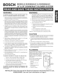
1
Model
No.
139.53225SRT
139.53325SRT
139.53425SRT
139.53628SRT
139.53629SRT
OP
139.53635SRT
139°53637SRT
139.53824SRT
For Resldentla
Use
E Safety
Precautions
m Assembly
m Installation
Read and follow
aH safety
rutes and operating
instructions
_fore
Care and Maintenance
first
Operation
use of this product_
Fasten
the manuat
the garage
H Adjustment
s Troubleshooting
PaRs List
near
door after
Complies with UL 325
_egulati_s effe_ve
January 1, 1_3
Sears,
Roebuck
and Co.
Hoffman
Estates, IL 60179
UoS.A.
Contents
Contents
A review of safety" a_e4 symbols
Youll need tools
2
3
Safety information regarding garage deer k_ks
and ropes ..............................................................
Eiectdoat requirememts ........................................
20
3
Testing your garage door for sticking, binding
and balance ................................................................. 3
H_ustrationd _ion@
d_r instaIla_on ..................... 4
/l/usl_tio, n of one@i_e @_r inst_tation .................. 5
CP_on inventory ............... :......................................... 6
H_-dware inventory ...................................................
7
Assembly se_on o pages 8 - 11
Assemble T--raii ...................................................
8
A_ch
c,_Ie pulley bracket ...................................... 8
Instil trolley ...........................................................
hsta_I the _ightand lens ........................................
19
Attach emergency reles_se re;)e and h_dle ..............
19
g
P_ten T_r_l }o o_ner ............................................ 9
Inst_sl/cha_r{(_ble ................................................ 10
Safety reversing _nsor infom_afon ..............................21
tn.sta_l_'_esdety reversing sensor ...........................
_, 23
F_ten d_r bracket (se@ona_ d_O ..............................
24
Fasten dear bracket (_e@i_
dc_0 ........................... 25
Conne_stdoor _q to #oHe¥ (sedJonat d<_O.................
26
_nn¢_
d_r a_
Adjustment
to troliey (on_i_
d_aO .............. 27
sc_ion -pages 28 - 30
Travellimit
adjustments
........................................
28
Force adjustments ............................................
29
Test the _fe_, reve_ing sensor .................................
3,0
Test U_e_fety
_eve_e _ystem ..................................... _O
O_raflon _#ety instm_ions...................................
31
Care of your opene_ ...........................................
31
M@n_en_ce _hedule .........................................
3'I
_ghten fl_e
chainemd _e ..................................
11
O_ra,_on of your o_ner ................................................ 32
installation section - pages 11 -- 27
Re_eiver _d remote control pr_mming
.................. 33
tns*alia_on sdety instr_adJons...........................
11
Ha_ng a premiere? ............................................
_, 35
Detem_ine header bracket I_tion
Rep_r p_ta, rail as_mb_y ............................................... 36
Se_ionai @y_r...................................................
12
Rep_r parts, instJation ........................................
_3
One@i_e door.......................................................
13
R_a_r pan.s, e_ner as_rnbly ...................................
37
InsteJ/the header b_cket ........................................ 14
A_ssor_es ..................................................
_S
Attd_chf.he Torail to header bracket .........................
15
Index .......................................................
39
PesitJon _e opener, ..............................................
16
How to order repair pa_ ........................................
40
H_ng _e opener .....................................................
17
M_ntenance agreement ........................................
Ins_JI
thewall_ntro[.....................................
18
Warranty ....................................................
40
A_ach sprr_ket _ver ................................................10
S_M
by review!.ng
these
im_nt
safeb_
aleM symbols
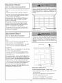
When you see th_s Safety Symbol on the following pages, it will aIeA you to the possibility of damage
to your garage door anNor the garage door opener if you do eot comply with the corresponding
instruct_onso Read the instpacdons carefu#y.
This garage door opener is designed and tested to offer safe service provided it Is Installed, operated_
mainta_ned and tested tn strict accordance with the safety Instructions
contained tn this manual
You'll
Need Tools
Dudng assembly, installation and adjustment of the opener, instructions will call for hand too_s shown befowo
_16_
9'16% y
Uaves de caja
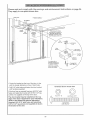
An unbalanced garage door might not reverse
when required and someone under the door
could be seriously injured or killed,
If your garage door binds, sticks or ts oat of
balance,
call for professional
garage door
service, Garage doors, door springs,
cablea,
pulleys, brackets and their hardware are under
extreme tension and can cause serious inJuc¢
or death, Do not try to loosen, move or adjust
them yourselft
Ropes left on a garage
door could cause
someone
to become
entangled and killed.
Remove all ropes connected to the door before
installing and operating the opener.
Identify the type and height of your door and any
speeia_ conditions that exist and any additional
matedais that may be required by referring to the
lists on page 4 or page 5
SECTIONAL
DOOR
To avoid damage
to the garage
door and
opener, disable locks before installing
and
ope_ttng the opener, U_ a w_d screw or nail
to ho_d locke in _he "O_n" (unlike)
_sttion,
Operation at other tha_ 120V 60 Ha wiil cause
o_eer maffunct_om and damage,
Before you begin, complete the following test to
make sure your door is balanced, and }s not
sticking or binding;
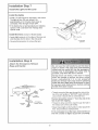
- Lift the door about hatfway as shown, Re_ease the
door, _tsho@d stay in place, sup_ded entire_y by
its spdngs,
, Raise and _ower the door to see if there is any
Before you begin, su_ey your garage area to
see whether any of the conditions
below apply
O
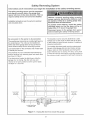
Based on your particular requirements, there are
severaI installation steps which might call for
materials and!or hardware not included in the carton.
,_Step 1 page ! 2 - Look at the wail or ceiling above
the garage door. The header bracket must be
securety fastened to stn3ctura_ sup_rts.
,, Step 5, page 17 - Do you have a finished ceiling in
your garage? if so, a suppo_ bracket and
additional fastening hardware may be required.
Safety* reve_ing sensor, page 21 _ Depending
upon gauge constructioe, wo¢_ blocks may need
to be fastened to mounting locations before
sensors are installed.
o The opener c_ be installed within 2 feet of the ieR
or dght of the door _e_er if there is a torsion spnng
or center bearing plate in the way d the header
bracket or d_r bracket area_ if.your door has
the opener must be insta#ed
in the center of the d_
See pages 12 &qd 24.
, Step 10, page 22 _ Alternate floor mounting of the
safety reversing sensor will require hardware not
, Step 11, page 24 o Do you have a steel, aluminum,
fiberglass or g!_ss panel dood* if so, hodzontai
and recital reinforcement is required.
• Do you have _q a_ess door in addition to the
garage d_
if not, Model 53702 Emergency
Key Re_ease is required, See page 38.
, Look at the garage door where it meets the fioor.
it must close o# the floor sit the way across.
Other_wlse, the safety reverse system may _ot
work properlyo See page 30. Floor or d_r should
be repaired.
You may find it helpful
, If your door is more than 7 feet high, see the longer
raiis available on page 38,
to refer back to this page as you proceed
4
with the _nstaitatton
of your opener:
0
Based on your particular requirements, there are
several insIailation steps which might _l br
materials @qS_orhardware not included in _e _&£on
One-Piece
Door With Track
Step I, page 13 o Look at the wafl o{ ceiiing above
the garage door. 'The header bracket must be
securely fastened to structural suppo_ls
* Step 5_ page t7 o Do you have a finished ceiling in
your garage? If so, a suppo£ bracket and
add tiona! fastening hardware (riot supplied) may
be required.
, Safety reversing sensor, page 21 Depending on
garage construction, wood blocks may need to be
securety fastened to mounting Iocations before
senso_ are installed.
Step 10, page 22 - Alternate floor mounting of the
safety reversing sensor will require hardware that
is not provided.
Step 11, page 25 _ Generally, a one pie_ door
does not require reinforcemenL tf your door is
lightweight, you _e refer to the information
relating to section_ doors on page 24.
,, Step 11, page 25 _ Depending on your dooCs
construction, you might need additional mounting
hardware for the door brackeL
o Do you have an a_ess door in addition to the
garage dc_r? if not, Model 53702 Emergency
Key Release is required. See page 38
, The gap between the bo_om of the garage
door and the floor cannot exceed 1/4".
Otherwise, the safety reverse system may not
work properly. See page 30. The floor or the door
should be repaired
You may find it helpful to refer back to this page as
you proceed with the installation of your o_ner.
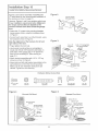
Opener
CaAon
Inventory
Your garage door o2_ner is packaged in two ca_ons which contain at_pa_s illustrated b@[ow, _fanylhing is
missing_ carefu!!y check the packing matedaL PaAs may be "stuck" in Me foam_ Hardware for assembly and
installation is shown on page 7
5_25 ('9, 5_5
(1)
Ugh_ed C4_
M_x_ieb 93225
Model
Compa_
5_
e¢_y
R_o{e
C_tt_
_4ea_r
Bt_ke_
C_'_aimar_8 C@lm
S4sfe_yRevergr_
£s_50{
_@ua_ng Bta_
V_4_hSquare H_@_ (2}
Arm _
Safety Revers_g
Wth S_
Sen_
(2)
6
M_¢_
S[_24
or'4y
Separate all hardware from the packages
in the rail carton and the opener
shown below, for the assembly
and installation
procedures.
AssembLy
T_o_ey ThCe_d_
Sh_
carton,
as
Hardware
(1 }
_16 _ {4}
Installation
I/4 _ 20 _ 7/16 _ (4}
Hardware
H_,_d_
R_t Gte_
,,.-'_1¢*
_8 _ _o;b__ (4)
NL4 _
_8i6t
Ro?e
Safety Reversing
Sensor
Installation
Hardware
Ca_ge _Rs
_/4" - 20 × 1_" (4)
Hex _¢_w
i/_-20 _ 11_"
(2)
Lo_ N_
_/4" _ (4)
_,/i#g N_ (2)
Assembly
To avoid installation
d:mcu[ties,
Section:
Pages
do not run the gauge
8-
d_r
opener
Ma_ sure _
tig_en
, Align _e 3 Torai_se_ons on a fiat suRace exactty
as shown° The end sections are identical Make
sure the "arrow labet ° on the center se_ion is
pointing toward the door..
, Inse_ the carnage
seat in the square
and pass through
section. Assemble
i_k
11
until :nst_
to do so.
n_ks are
nuts
{_
o_ratJon, nef_ anddOr
aa_n_
d_
re_r_lm
bolts so the square bolt necks
holes in the T-rai! end sections
the round holes in T_rait center
lock nuts, ensure alignment and
%
Hardware Shown Actual S:ze
END of "T _a_l
, Pos_on #_e _ble putiey bracket on #_e front end:of the
T_raii as shown Fasten s_cure_yv_4th_e hardware,
_16 _ 18×;7/8"
Sd!6 _ 18
_1_
Whe_ t_ghte_ing
_e sorews_
tO t_he rail
Otherwise,
whe_ o_aer
the
_s
Assembly
Install
Hardware Shown
Actua_ Size
Step 2
the Trolley
on the T_ra#
- Attach the threaded sha_ to the trotley wi_ the
I_xckwasher and nuts as shown
L¢_k W_;_t
_'16"
Nut
_1_ _ ,, 18
Trolley
As a tem_rary stop. insed a screwdnver into the
hole in the front end d the %rait.
Slide the trolley assembly _ong the rail to the
screwdriver stop
if trolley hits against any nuts on the T_rai_, the
bolts and Ruts were attached from the wrong
side and must _ reposittoned. Review Step 1.
Assembly
Fasten
the
Step 3
T-rail
to the
Opener
To fasten rail, use only those screws mounted
in the top of the opener. Any other screws will
cause serious damage to the opener.
Place the opener on packing material to protect
the cover. For coevenience, pat a support under
the came pui_ey brackeL
Remove the (2) 5/I6_18×1/2 _ washered _rews
mounted in the top d the opener_
Was_e_e_J _¢ew
- Atign the holes in the back seGion of the %r'ai_ with
the holes in the opener.
* Fasten the rail with _e (2) washer_J screws
previously remove& Tighten securely.
Remember to use only these screwsf Any other
screws wil! cause serious damage to the opener.
lnse_ a 5/16"-18x7/8" hex screw
stop hole in the T.-rail as shown. Tighten securely
with a 5116 _ lock washer and nuL This screw limits
trolley travel in the UP direction.
Hardware
Hex _tew
Shown
Actual Size
Nut
L¢_
Wa#_e_
9
Assembly
Install
Attach
the
Step 4
Chain/Cab@
the Sprocket
&
Cover
Figure
2
o_
_OCkef
Detach the came loop from the capon and fasten it
to the tro!fey with a master link from #Be hardware
bag See master link procedure, Figure 'I,
F_gure 3
WiSh the trolley against the serewdnvec dispense
the c_>_e around the pu_tey,
Ma$_er
Unk
, Pro@_edback around the opener sprockeL
Figure 2. Be sure sprocket teeth engage t}he
chain, Continue forward to the trolley
thresd_ shaft, Figure 3.
Use the se_:md master _nk to connect
the chain to the flat end of the shaft.
Check to make sure the chain is
not twtsted,
, Remove the screwdriver
Master LJ_k Pr_r_;
n The Oit_a
P_sh pins of r_3_stet link bar
through _b_e k_p a_ hole in
#on_ end d t_liey, Push _p
over pins_nd into risk;hoe
Stag c_po_ spdng over _ep
a_ into _yotchee unti_ _t_h
pins are s_ure_y
i_kedo
To a_ach the sprocket
cover:
InseA the back t_ inthe opener sbt. Squeeze the
cover slightly and inseA the front tab in the s/st on
the mounting plate,
10
}e_tN_
C_Jte_ Nu_
Spir_theinnernutandiockwasherdownthe
threadedshaftawayfromthetrolley
Totightenthechain,turnouternutin thed#ection
shown.As you turn the nut, keep the chain
from Misting.
- When the chain is appm×imate_y 1/2" above the
base of the T-rail at its midpoint, re-tighten the
inner nut to secure the adjustment.
Sprocket
noise can result if chain is either too
Ch_
When installation
chain droop with
the chain returns
door is open, do
}s compete, you may notice some
the door ciosed This is normal if
to the position shown when the
not re-adjust the chain.
I
NOTE: During future maintenance,
ALWAYS
pulI the emergency reiease handle to disconnect
trolley before adiusting chain.
You have now finished
warnings
before
assembling
proceeding
IMPORTANT
your
garage
to the installation
ALL INSTALLA_ON
Please
read the following
section:
INSTALLATION
To reduce the risk of severe
1. READ AND FOLLOW
door opener.
i
"U
INSTRUCTIONS
or death to persons:
INSTRUCTIONS.
2. install only on a properly balanced and lubricated garage door. An improperly balanced door
may not reverse and could reautt in severe tnju_ or death. Repairs to cables, .spring assemblies
and other hardware must be made by a professional
service person before installing opener_
3. Disable aii iocks and remove all ropes connected to the garage door before ins:tailing the opener._
Ropes connected to a garage doer can cause entanglement
and death.
4. _f possible, install door opener 7 feet or more above floor with the emergency
mounted 6 feet above the floor_
5_ Do not connect
the opener to power source until instructed
release handle
to do so,
6. Locate the Wall Control within sight of the door at a minimum height of 5 feet where small
children cannot reach and away from all moving pa_s of the door.
7. Install the User Safe_ instruction
Label on the wall adjacent to the control bu_on and the
Maintenance instruction
Labei in a prominent location on the inside of the garage door.
8. Upon completion of the installation,
the door must reverse when it comes in contact with a
oneqnch high object or a 2x4 laid fiat on the floor,
9. Do not wear watches, rings or loose clothing whRe installing or servicing an opener. Jewelq
loose clothing can be caught in the mechanism of the garage door or the opener.
11
or
installation
installation
Determine
Step
Header
Section:
Pages
12-
27
1
Bracket
Location
if the header bracket ts not rigtdiy fasten_
to
a structural
support
on the header watt or
cet[tng_ the safety reverse system may not
work property (see page 30) The door might
not reverse when required, and could cause
installation procedures van/according
to
garage door bjpes_ Follow the instructions
which appty to your door,
The garage door springs,
cables, putteys,
brackets and theft hardware are under extreme
tension,
Do not attempt to loosen_ move or
adjust them yoursef£ Serious personal inju_
or death could result, Call for protessior_aI
garage door servfceo
Str#_utal
_(y_p_.s
............ _ Ciose the door and mark the inside
...... _..............
veAieal centertine of the garage door
_:_
_ilt
* E£end the line onto the header wall
above the de_:)r
Remember, you can fasten the
header bracket within 2 feet of the
left or right of the door center only tf
a torsion spring or center bearing
p_ate is in the way; or' you can a_ach
it to the ceiling (refer to page 14)
when clearance ts m_nimaL (It may
be mounted on the wall upstde down
_
if necessary,
1/2 j
.........
to gain appro×imate_y
If you need to install the header b_acket
o,_ a 2x4 (on wall or ceiling), use lag
screws (not supplied) to securely @sten
the 2x4 to structu£d sqppof_s as shown
here and on page t&
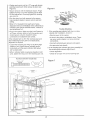
Ce_r_g
He_der
Open your door to the highest
point of travel as shown Draw
an intersecting hodzanta_ line
on the header wat/2 above
the high point. This height wi_/
provide traw_t clearance for the
top edge of the door.
Door clearance brackets are
available for sectional doors
when headroom clearance is
_ess than 2°_ See accessory
page 38
Tr_:k
of Trav_
ocH,) f
...........
Sectiona! door
wtth curved track
Proceed
to
Step
2_ page
14o
12
One,_p_ece door
with horizontal track
Read the Safety
instructions
on page 12. They also apply
to doors
without
tracks.
,Ciose #_e d_r and ma_'kthe
inside veRicai centerline of
your garage door. E_end the
line onto the header wall
above door
tf headr_m c{earance {s
minimal, you can instai_ the
header bracket on the ceiling.
See page 14.
header bMcket on a 2x4 (on
wall or ceiling), use lag _rews
(not suppti_) to secure_J
fasten the 2x# to structural
On.piece
door without
, Open your door to the highest
shown Measure the distance
door to the floor° Subtract t,he
door. Add 8 _ to the remainder.
One-pi_e
door without
pivot hardware
track
EXAMPLE
_int of trave_ as
from the top d the
actual height d the
(See Example).
Distance from top of door
(at highest point of travel) to fk_r ....................
92"
Actua_ height of dc@r .....................................
88"
- Close the door and draw an inte_ectJng horizontal
line on the header w_l at the dete_ined
height..
Remainder ..................................................................
Add ...................................................
8
if the total number of inches exceeds the height
available in your garage, use the maximum
height possible, or refer to page 14 for ceiling
ins_llatfon.
Proceed
track
Bracket height on header wali .............................. =12"
(Measure UP from top of CLOSED door.)
to Step 2, page 14.
13
Youcanat_ch the headerbracketeitherto the
wail above the garage door, or to the ceiling.
Follow the tnstr_Jctions which will work _st for
your pa_leuJar requirements.
Fasten
the
Header
Bracket
to the Wall
* Mark either set of bracket holes (do not use _e
holes designated for ce#ing mount), Ddl{ _16" pilot
holes and fasten the bracket securely to a stm_u_
suppo_ with the hardware provided.
o Center the bracket on the veAical guideline with
the bo_om edge of the bracket on the hodzonta[
tine as shown (with the arrow pointing toward the
W_
Hardware Shown Actua_ S_ze
Fasten
the
Header
Bracket
, Extend the ve_icat guide{ine onto the ceiling as
shown,
- Center the bracket on the ve_ica_ maP_ no more
than 6" from the wall, Make sure the arrew is
pointing toward the wall The bracket can be
mounted flush against the ceiling when clearance
is minima_
Mark h@es designated for ceiling mount only Drill
3/16 _ pilot holes and fasten bracket securely to a
stru_ura_ suppo_ with the hardware pro,tided
r_i_g
M_r_Sng Ho_es
The n_ how is for _'6_n
9 ®_y,
Yo,J must _se _ag _r_s
lo _T_un_
_h@header b_'_ck_{
14
to the Ceiling
installation
Attach
Step 3
the Torafl to the Header
Bracket
o Position the o_ner on the garage fl_r below the
header bracket, Use packing material as a
If the door spring Is in the way you'l! need help,
Have someone hold the opener securely on a
tem_ra_
suppoA to allow the T-rail to clear the
o Position the _b_e puiley bracket against the header
bracket
Align the bracket holes and ioin with a clevis p_n as
shewn,
hse_ a r_ng fastener to secure,
Hardware
Shown Actual Size
O
Clevis P_
15
Installation
Position
Step 4
the Opener
Folow instructions
type as l_ustrated.
wMch
A 2×4 [aid fiat is convenient
door4o-T-ra/distance°
apply to your door
for setting
an ideal
Raise the opener onto a stepladder,
You will ne_
help at this point it the ladder _a
+Open the door a/the way and place a 2×4 _aid flat
on the top section beneath the T-ra/
If the top panel hits the trolley when you raise
the door, puff down on the troltey release arm lo
disconnect the inner and outer sections. The
trolley can remain disconnected
until S_ep 12 is
With the door fu/y open and paratel to the floor,
measure the distance from the floor to the top of
the door
Using a stepladder as a sup_)£, raise the opener
to the same distance as the d_r from the floor (it
will be at a stght angle as shown).
The top of the door should be level with the top of
the opener Do not position the opener more than
2'_above this point
16
installation
Hang
Step 5
the Opener
Two represen_gve
installations
are showo.
Yours may be different, Hanging brackets should
be &qgted, Figure 1, to provide rigid support On
finished ceilings, Figure 2, a_ach a sturdy metat
bracket to st_Jctural supports before installing the
opener. The bracket and fastening hardware are not
supplied. See accessory page 38.
Figure
1
Measure the distance from each side of the opener
to the strdctura! support°
Cut both pieces of the hanging bracket to requ red
DdH 3/16" pilot h@es in the structural supports
Attach one end of each bracket to a support with
5/16"xl _.7/8_ lag screws.
,, Fasten the opener to _he hanging brackets with
5/t 6_18x7/8" screws, _ock washers and nuts.
Check to make sure the Torai/is centered over the
door (or in _ine with the header bracket if the
bracket is not centered above the doo0_
_'I 6%18x7/8 _ _e'w
Remove the 2x4 Operate the d(x_r manuaHyo _fthe
door hits the rai_, raise the header bracket
Hardware
Shown Actua_ Size
Lag Screw
Hex
@'16
Screw
18×778
_
Nut
_#16"_18
t,.6_kWAshef
_i6"
17
Installation
InstMt
Step 6
the Wall Control
Children operath_g or p_ay_n9 w_th a garage
door opener can injure themselves or others_
The garage door could dose and cause serious
injury or death
Install the Wall Control (or any additionat push
buttons) out of the reach of chHdrer_ and away
from aH moving parts of the door and door
hardware, but where the
door is visJbleo
Do not allow children
to operate the p_eh
buYeR(s) or the remote contro{(s)o
, Stdp 1/4° of [ns@ation from one end of the be{{
wre; connect the wire to the two screw terminals
on the back of the Wail Centre/: white to 2 and
white!red to 1
Locate the Wall Control within sight of the door
at a minimum height of 5 feet where small
children cannot reach_ and away from all
moving parts of the door and door hardware.
Fasten the Lighted Push Button Wa_l Contro_
securely with 6ABxl 1,'2" screws The consote
style uses 6AB×I" screws _finstalling into d_waIL
dri!_ 5/32" hoes and use the anchors provided
Run the be/[ wire up the wall and across the ceiling
to the opener_ Use insulated staples to secure the
wre in severa_ @aces. Be cater@ not to pieree the
wire with a stapIe, thereby resulting in a sho_.
Receiver terminal _rews and the antenr@ are
_ocated on the back pane_ of the opener. Position
the antenna wire as shown.
A moving garbage door could injure someone
under it Activate the opener on_y when the
door is pro_r[y
adjusted, you can s_ it e_ear_y,
and there are no obstructions to door travel
Do NOT connect the power and operate the
opener at this dine. The trolley wH[ trave_ to the
f@! open position
but will not return to the
c_oee posft_on
until the sensor
beam is
connected and proper_y aligned.
See Safety Reversing
begirming on page 2t.
Then connect the bell wire to Ihe opener terminal
screws: white to 2; whitdred to I.
Remember to affix the User Safety Instruction
tube[ to the walf near the Wall Control, and the
Maintenance _nstruetion [abe_ in a prominent
_oeat_on oe the {aside of the garage d_r.
ff the label adhesive will not adhere to your garage
wail surface (or becomes bose with time) use _acks
to secure the [abe_ alongs de the wa_l control
Outdoor
Connections
Deluxe
D 0' Wa;i Ar_chocs
Deh_A_ W_# O_vt_'@
[ igh[_ Con_ole
Wt_ Con_to_
Key Switch Accessory
Lighted
Hardware Shown Actual Size
6AB x ¢* 8_tew
Co_tsole Wail r;on tel
_nstructions
To opener termin_ screws: white to 2; whitdr¢_d to I
Page 32 explains bow to operate the opener using
the lighted push bar or button as w@/as the L.._k
and L.ight features on the Deiuxe Wail CorstroL
Lghed
Sensor
Ugh_t
P_sh auAe#
wa_ Coa{_ea
18
Waft Control
Console
Waif
Control
Installation
Step 7
Instafl
the Light
and the Lens
Instal|
the lights
- Install a 75 watt me_imum light bulb in the stoker.
The light will turn ON and remain lit for
approximately 4q/2 minutes when _wer is
connected. Then the light will turn OFF.
, If the bulb bums out prematurely due to vibration,
replace it with a standard neck "Garage Door
Install
Ught
the lens (except for Modef 53225)
Apply slight pressure on IJsesides of the _ens and
slide _e tabs into the slots in the end p_ef
, Reverse the procedure to remove the fens°
lnstalJation
Attach
the
Step 8
Emergency
Release
Do not use the red handle to
open or closed, The rope knot
untied and you could Carl. Use
release only to d_sengage the
possible, only when the door ts
pull the door
couid become
the emergency
trolley and:, if
etosed.
Garage doors are heavy. If the door is open
when the handle is pulled, the door could
close
inadvertently
if ft is not properly
balanced, Sedous injury may result to persons
under the door, Make sure the doorway ts clear
of persons
and obstructions
before pulling
handle when door is open,
- Thread one end of the rope through the hole in the
top of the red handle so "NOTICE" reads dght side
up as shown Secure with an overh_d keel
The knot should be at least 1" from the end of the
rope to prevent slipping,
R®e
, Thread the other end of the rope through the hole in
the release arm of the outer trolley
* Adjust rope length so the handie is 6 feet above the
floor. Secure with an overhand knoL
If it is necessary to cut the rope, heat seal the cut
end with a match or lighter to prevent unraveling.
t9
ins aliat on
t
Electrical
j
Step 9
Requirements
"Toreduce the dsk of eleetdc shock, your garage
door opener has a grounding type plug with a third
grounding pin. This pbg will only fit into a grounding
If the plug doesnt fit into the outlet you have,
conta_ a qu_ifi_d el6_Cia_ to install the pro_r
outlet.
{
]
"Toavoid inataflatlOn difficulties,
do not run the opener at this time,
If permanent
wiring
is required
by your
local code,
To prevent eiectrocufion,
remove power from
the garage door opener and from the circuit
you plan to use for the permanent connection,
To make a permanent oannection through the
718_ diameter hole in the top of the opener
(according to I_l code):
Remove the opener cover screws and set the
cover aside_
Remove the attached 3 prong cord
, Connect the black (line) wire to the screw on the
b_ass terminal;: the white (neutral) wire to the
screw on the shyer terminal7 and td-_eground wire
to the green ground screw. The opener must be
o Reinstall the cover.
To avoid insfatlation dtfficutties_
do not run the opener at this time.
2O
refer to the following
procedure:
Safety
Information
you1] need before
Reversing
you begin the installation
The safety reversing sensor must _ connected
and aligned correctly before the garage door
opener wlil move in the down direction. This is a
required _fety device and cannot be disabled,
Instalia#on pr_edures
System
of the safety
reversing
sensor.
Without a properly
working safety reversing
sensor, persona (particularly
children) could
be in]u_
or killed by a closing garage door.
Read and follow all instructions.
are the same for sedionat
To protect small children,
Install the safety
reversing sensor so that the beam wi[[ be no
higher than 4"4" above the garage fi_ro
Disconnect
power to the garage door opener
before installing the safety reversing sensor.
Be sure po'#er to the opener
is disconnected.
The bracket_ must be securely fastened to a solid
sudar_ such as the studs on either side of the door,
or add a piece of wood at each location if installing in
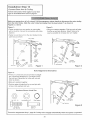
The sending eye transmits an invisible tight _am to
the receiving eye The units can be installed on
eider side of the garage door as long as the sun
never shines directly into the receiving eye lens,
Lc_k at the label on the eonneGor end of each use
The invisible Hght beam path must be unobstnJcted.
No pad of ttie garage door (or door tracks, spdngs,
hinges_ roIIers or other hardware} can interrupt the
beam whiie the d_3r is closing If it does, use a pie_
of wr_d te build out each sensor mounting iocation to
the minimum depth required for Ight beam c_earance
to identiPy the sensors.
The brackets must be connected and fastened so
that the sending and receiving eyes face each other
as shown in Figure I.
If an obstruct on breaks the light beam while the
garage door is c_osing_ the door wilt stop and
reverse to fuil open position and the opener lights
will flash for 5 seconds
a_3ve
f_rot_::_n
Figure
Area
1 : Facing the door from inside the garage
21
f;c_
Figures2 and3 showassembly
ofbracke_and
Figure
2
°C" wrap based on the recommended instafiation of
the sensors as shown on page 21
Me#_tk_
Br_k_t
However, Figures 4 and 5 are variations which may
ins_i_ation requirements baser Make sure
the wraps and brackets are align_ so the
sensors will face each other across _e garage
door,
Fasten the "C_ wraps to the mounting brackets
having square holes, using the hardware shown
n Figure 2
Connect each assembly to a slo_ed bracket, using
the hardware shown in Figure 3_
Note the alignment of the brackets
right stdes of the door_
for left and
Figure
3
Actual
Size
, Finger tighten the lock nuts
o Use bracket mounting holes as a template to
locate and drill (2) 3/16 _ diameter pilot holes on
both sides d the g_age door, 4%6` above the
floor but not exceeding 6t (See warning on
AEach bracket assemblies with 1/4"xl-1/2 _ _ag
_crews as shown in Figure 3.
Adiust dght and le_ side bracket assemblies to the
same distance out from the mounting sudace.
Make sure all door hardware obstructions are
cleared Tighten the nuts securely.
Hardware
#10
32 _ :_8"
#10 x 32
Shown
1/4 x 1_1_
1/4" _o_& Nut
Figure
A_ternate Wall Mount
A_temate
_i_h Sq_e
:
r
:i
f
f:_
A,¢>
&/'
,o
5
Ho e8
wlb_te
"Z_:....
22
FIoo_
Mount
'_Centereachsensorunitin a "C_wrapwithlenses
pointingtowardeachotheracrossthed_r (see
Figure
6
SecuresensorswiththehardwareshownFinger
tightenthewingnutonthe receMng eye to allow
for final adjustmenL Securely tighten the sending
eye wing nut,
, Run the wires from _th sen_rs to _e opener_
Use insulated stapJes to secure wire to walt and
Step 1/4 _ of insulation from each set of wires.
Separate white and whit_lblack wires sufficien#y to
cermet to the opener terminal screws: white to 2
and white,_lack to 3.
1 If the sending eye indicator light does r_ot glow
steadily after !nstJlation, check for:
Plug in the opener.. Make sure the Lock Feature is
off, Green indicator !ights in both the sending and
receiving eyes wi/i gtow steadily [f widng
connections and aIignment are correct.
- Kle_tdc power to the opener.
A short in the white or white,_l_k wres These
can _cur under staples or at screw tem_in_
connections,
if the indicator light is offin the receiviog eye (and
the invisible light beam path is not obstru_ed)_
alignment is required
* Incorrect widng between senso_s and opener,
Loosen the receiving eye wing nut to alfow slight
rotatiGq of unit. Adjust sensor vertically newer
hodzontaily until the green indicator light glows
, An open wke (wre break}.
2. if the sen#ing eye indicator light clews stead@ but
the receiving eye [email protected] light doesn't:
o Check alignment
When indicator lights are glowing steadily in bo_h
units, tighten the wing nut in the receiving eye uniL
Hardware
, Check for an open wire to the receiving eye.
Shown Actual Size
Figure
7
O_;_r_et
7 e rmi_9t,_;
_#z4Wre
i
OPffN_R
Pro_P_
A_-ea
23
TERMINAL
_R[WS
Installation
Fasten
Door
Step 11
Bracket
To prevent
damage
to steel,
aluminum_
fiberglass
or glass pane_ doors,
always
reinforce the inside of the door _th veAicaily
and horizontally with an angle Iron.
Foliow instructions
which apply to your door
type as illustrated beiow or on page 25°
Figure
Center the door bracket on the previously marked
vertical guideline used for the header bracket
installation
- Position the bracket on lhe face ot the door within
the following limits:
A) The top edge of the bracket 2°4 '` below the top
edge of the door.
Hardware
B) The top edge d the bracket directly below any
structural suppoM across the top of the door.
Mark and ddti &ll 6" _eft and right fastening holes
Secure the bracket as shown in Figure I if there is
ve_'ticaI reinforcemenL
if your installation doesn't require vertical reinforce
meat but does need top and bottom fastening holes
_or the door brackeL position the door p_ate over the
door b_acket as shown in Figure 2 Fasten securely
with hardware shown in Figure 1
24
Shown
Actual Size
i
P_ease read and comply
They apply to oneopieoe
with the warnings
doors also,
and reinforcement
instructions
on page 24.
* Center the bracket on the top of the doer, in fine
with the header bracket as shown. Mark hotes.
Hardware Shown Actual Size
Drill 5/16 _ pilot holes and fasten _e door bracket
with hardware supplied_
_fthe door has no exposed framing, drill 3/16" pilot
holes &nd fasten the bracket with 5/16_xl _1/2" lag
screws (not supplied) to the top of the door.
The door bracket may be installed on the top
edge of the door ff required for your installation.
(Rder to the dotted line optional placement
drawing.) Drill 3/16" pilot holes and substitute
5/16"x1_1_" lag screws (not supplied) to fasten
the bracket to the door.
25
Installation
Connect
Step
Door Arm
!2
to TrMley
Fotlow _nstructtons which appy to your door
type as illustrated below and on page 27,
Make sure garage door ts fully c_o_d. Pull the emergency release handle to disco#nect _e outer trollley
from the inner trolley, Slide the outer trolley back (away from the door) about 2" as shown _n
Figures I, 2 and 3.
F_gare 1:
F_gure 2:
Fasten straight door arm section to outer trol[ey
with a cevis pin_ Secure the connection with a ring
fastener
Bdng arm s6stJons together, Find two pairs of holes
that _ine up and join se_ions Select ho_es as far
apart as possible to increase door arm rigidib:,o
Fasten cawed door arm to the doer bracket in the
same
way
as shown.
[n_r
Toffy
Hole Affgnment
Alternative
Figure 3:
_,if holes in catered arm are above bores in straight
arm, disconnect straight am'L Cut about 6" from
the solid end, Reconnect to trolley with cut end
down as shown_
Bring arm sections together.
Find two pairs of hoies that line up and join with
screws, lock washers and r_uts,
Hardware
Nui
5f16" _ 18
L_k
Shown Actual Size
Washer
_l_'J"
e#_# F_slene¢
Figure
He_: _;_ew
Proc_d
to Adjustment
CI_s
@
otep
Pi_
t, page 28, Troiiey
wH[ re_ngage
26
automatically
when
the opener
ts operated_
3
Assemblethe DoorArm:
,, Fasten the straight and curved door am_ secl,ions
toge_er to lhe longest possible length (with a 2 or
. With the door closed, connect the straight door
am s_tion to the door bracket with a c_evis pin
, Secure with a ring fastener.
On one-pie_e doo_, before connedJng _e d_r a_ to the trolby the t_.¢el limits must _ a_usted. Um_ adiustment
screws are I<%ated on the/eft side panei as shown on page 28. Follow adiustment pnx:edures below
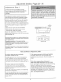
J ........ C_
E#_ck_a_d S_&nt
Adiustment
Proc_ures
for One-Pi_e
Ope_ Door Adjustment:
Decrease UP limit
Doors
Closed Door Adjustment:
D_rease DOWN limit
- Turn the UP t_mitadiustment screw counter,cl_kwise 5-1/2 turns
Turn the DOWN Iim}t adiustment screw cbckwise
5
• Press the Wai_ Controt push bar or button. The
troliey witl travel to the fully open _sition.
• Press _he Wa{_Cont_)I push bar or button. The
troliey wiIt trave_ to the fully ctosed position.
- Manu_ly raise the door to the open position
(paralle_ to the floor), and _ifl the door arm to the
trolley_ The a_m shouid touch the trolley lust in
back of the door arm connecter hole. Refer to the
fully open trolley/door am positio_ in the
illustratiom If the arm does not extend far enough,
adjust the _imit fu_her. One full turn equals 2" of
. Manually etose the door and iiff _e d_r arm to the
troltey. The arm should touch the trolley just ahead
of the door arm connector hob. Refer _o the fufty
c_osed trolley/door arm positions in the iliustratiom if
_he am is beh}nd the connector ho_e, adiust the iimit
further. One ftJl_turn equals 2" of troliey travei
Connect
the door arm to the trolley
. Close the door and ioin the eu_ed arm to the connector hole in [he trot_ey with the remaining clevis pin. It may
be necessa_ to lift the door slightly to make the connection,
- Secure with a nng fastener.
. Run the opener through a comptete travel cycled if the door has a slight "backward" slant in fu_l open position
as shown in the illustration, decrease the UP limit until the d_r is paraItel to the floor.
27
Adjustment
Adjustment
Adjust
Section:
Pages
28-
30
Step 1
the UP and DOWN
Limits
}mproper adjustment
of the trave! Hmits will
inte_ere w}th the proper operation of the safety
reverse system_ The door m_ght not reverse
properly
when required
and could seriously
injure or kill someone under it, Test the safety
reverse system following aH adjustments to the
trave| HInes, See page 30.
Do not make any i{mit adjustments until the
safety reversing sensors are completely
installed°
Limit adjustment settings regu{ate the points at
which Lhe doer will stop when moving up o_ down,
The door will stQo in the up direc_on # anything
intederes with door t_avel The door wil_ reverse in
the down direction if anything intederes with the
door trave_ (including binding or unbalanced doors)_
To operate the opener, press the Wa_ Centre! push
bar, Run the opener through a complete trave_
A_us_men_
o Does the door open and close @mpletely?
Does the door stay closed and not reverse
unintentionally when tulty closed?
/f your door passes beth of these tests, no limit
adjustments are necessaPy unless the reversing test
f
Le_ _
Pa_i
Adjustment procedures are outlined below° Run
the opener through a complete travel cycle afler
Repeated operat}on of the opener dur}eg
adjustment procedures may cause the motor to
overheat and shot off, Stmp}y wait 15 minutes
and t_ again°
Read the pr,_edures carefuNy before proceeding to
Adjustment Step 2 Use a screwdriver to make limit
How and When to Adjust
}f the door does not open completely
but opens at least f}ve feet
hcrease up travel Turn the UP limit adjustment
screw ciockwise. One turn equals 2" of travel
}f door d_s not open at }east 5 feet: Adjust the
UP (open) force as e×plained in Adjustment Step 2,
the Limits
If the opener reverses in folly c}os_ pos}tton
Decrease down travel Turn the DOWN _imit
adiustment screw c_ockwise One turn equals 2 _ of
travel
]if the door reverses when dosing and
there is no vistb}e _ntederence to trave_ cycle
if the opener _ights are flashing_ the Safety Reversing
Sensor is obstru_ed Remove the obstrue_en
if the door does not close completely
hcrease obwn travel Turn the DOWN limit
adiustment screw counterclockwise One turn
equals 2" of travel
Test the door for binding: Pull the emergency
handle Manually open and c_ose the door, If
is binding, call fer garage door service ff the
not binding or unbalanced, adjust the DOWN
force. See Adjustment Step 2.
ff dc8r sfli_ won't c_ose compiete_y, try lengthening
the door arm, (Page 26,)
if you have adjusted the door a_ to the m_imum
length and the door still wil_ not dose completely,
Iower the header bracket, See _nstaHatJonStep 1,
pages 1211&
28
re}ea_
the door
dr_r is
(close)
Too much force on the d_r
wil! interfere with
the proper operation
of the safety reverse
system, The door might not reverse properly
when require_ and could seriously injure or kill
someone under it. Do not increase the force
_yond
the minimum amount required to dose
the d_r. Do not use the force adjustments
to
compensate
for a binding or sticking garage
door, Test the safety reverse system fol|owing
aH adju_ments to force levets, See page 30,
Forceadiustment
controlsareiocatedontheback
panelof theopener.Forceadiustment
ee_ings
regulatetheamountofpowerrequiredto openand
dosethedoor
Thedoorwillstop in the up direction if &%_hing
intederes with its travel The door will reverse in the
down direction if an_hing intederes with its travel
(including binding or unbalanced doors).
if the fercJes are set too light, door travel may be
interrupted by nu,_sance reversats in the down
dire<:tion and stops in the up direclion. Weather
cond}tions can affect the door movement so
occasional adiustment may be needed.
_ot_
Adtu_l_n_
The maximum force ad}ustment r_ge is 260 d_rees,
about 3,/4 d a complete turn Do not force controls
beyond that _xsinL Turn force adjustment controts
with a screwdr ver.
A_iir_
L_L_
How and When to Adjust
the Forces
Make 10 degree turn adjustments unti_ the door stops
easily. After each adiustment, run the opener through
a Gsmp_ete travel cycle,
Test the DOWN (close) force
Grasp the door bo_om when the door is about
haffway through DOWN (ctose) travel. The door
should reverse Reversal halfway through down
travel does not guarantee reversal on a two4nch
obstruction.
See page 3& If the doer is hard to
hold or doesnt reverse, decrease the DOWN (close)
force by turning the control counterc!oekwise
ff the door doesn't
open at least 5 feet
increase UP (Open) force by turning the control
clockwise Make 10 degree turn adiustments untii
door opens completely. Re-adjust the UP limit if
neeessa_. After each adjustment, run the opener
through a complete travel cycle.
Make 10 degree turn adiustments unti_ the door
reve_%es normally After each adiustment, run the
opener through a complete cycle.
if the door reverses during the down (ciose)
and the opener lights aren't flashing
Test the UP (open) force
cycle
increase DOWN (dose) force by turning the control
c!oskwise. Make 10 degree turn adjustments until the
door completes a close cycle. After each adjustment,
run the opener through a cornplete travel cycle. Do
not increase the force beyond the minimum
amount required to close the door,
Grasp the door bottom when the door is about
halfway through UP (open) travel The door shouid
stop If the door is hard to hotd or doesn_ stop,
decrease UP (open) force by turning the control
counterclockwise.
29
Test
The
Safety"
Reversing
Sense
Press the remote control push button to open the
door.
. Place the opener ca4on in the path of the door.
Press the remote control push bu_on to close the
door The deer will not move more than an
and the opener f@ht will flash.
Prdessional
se_Jce is required if the opener
ctoses the door when the safe_y reversing
sensor is obstructed.
I
The garage door opener wH! not ctose from a
remote control if the indicator light in either
sensor is off(aleAing
you to the fact that the
sensor is misaligned or obstructed).
The garage door can be closed by pressing and
holding the Wa}_ Control push bar or bu_on unti_
down travel is completed,
Adjustment
Test
the
Safety
sa_,wRew_.ts
_gse_4_
_
Sa_et
Step 4
Reverse
System
Failure to test and adjust the safety reverse
system may result in serious injury or death to
persons
trapped by a closing
garage dean
Repeat this test once a month and adjust as
nc_ded_
Test.:
Place a on@inch board (or a 2x4 _md flat} on the
floor centered under the garage door.
Operate the door in the down direction. The doer
must reverse on s#lking the obstruction,
_fthe door steps on the obstruetion_ it isnot traveling
far" enough in the down direction.
o hcrease the DOWN limit by turning the DOWN
Hmit adiustment screw countercJc_wise
1/4 turn.
Repeat the test
On a sectional door, make sure Ilmff adjustments
do not force the door arm beyond a straight up
and down positiom _
_e }liasfmatlon on page 26
, When the door reverses on the onednch t_ard,
remove the obstruction and mn the opener througt_
3 or 4 complete travel _ie_es to test a_diustment.
|f the door wH! not reverse after repeated
adiustment
atIempts, call Sears Service Center
for garage door opener service.
Important
safety
Repeat Adjustment
check
Steps 1, 2 and 4 after:
o Each adiustment of door arm Ienggq, force controls
or _imRcontrols
o Any repair to or adjustment of the garage door
(including spdngs and hardware},
o Any repair to or buckling of the garage floor.
Any repair to or ad:iustment of the opener
30
iMPORTANT
SAFETY
iNSTRUCTiONS
To reduce the risk of severe injury or death to persons:
t READ AND FOLLOW ALL |NSTRUCT!ONS,
2. Do not permit children either to operate
locagon inaccess_Me to chiidren.
or to play with the opener_ K_p
remote contro!
in a
3. Operate opener only when the door ts _n full view and free from any obstruction.
K_p the door tn
sight until it is completely closed. NO ONE SHOULD CROSS THE PATH OF THE MOVING DOOR.
4. Check safety reversal system monthty_ See page 30. The garage door MUST reverse on contact
with a oneqnch (or a 2x4 board iatd fiat) object placed on the floor. If an adjustment Is made to
either the force or the limit of travet, both adiustments may be needed and the safety rever_l
system must be checked. Failure to property adjust the opener may result in severe injutTy or death.
5. if possible, use the emergency retease Only when the door is in a c!os_ position. Caution should
be taken whenever the disconnect
cord is actuated with the door open. Weak or broken springs
may cause the door to fail rapidly, causing injury or death to persons.
6. KEEP GARAGE DOORS PROPERLY BALANCED. S_ page 3. An improperly balanced door may not
reverse when required and could result in severe injury or deat,5. Repairs to _bles, spring
assemblies and other hardware must be made by a professional garage door _rson.
7. Discoenect
covers.
the e{ectric power to the garage door opener before making any repairs or removing
the
s.SAVE THESE INSTRUCTIONS°
Care of Your Opener
Limit and force adjustment
Limit Controls
Ad!ustmer_
controls
_e remote control
1%e opener must learn the code oNany new remote
control Page 33 explains how to program your
receiver and how to erase a!l codes if required Self
ser,4ce of you_'reseiver is not recommended If
seP4ce is r-_eeded contact your nearest Sears
Service Center
Force Controls
L_bga
_he remote control
Weather conditions may cause some minor
changes in door operation requiring some re,*
adjustments,
paAicularly dudng the first year of
ba_e_
The green test light should glow and the opener
should operate when the remote contr@ is activated
If the green test light is dim or does not eeme on,
Pages 28 and 29 refer to the limit and force
adiustments Only a screwdriver s required_ FoIIow
the instructions carefu{_y
The 12 Voit bakery should produce power for at least
a year
Dispose
Repeat the safety revers_ test (page 30) after any
adjustment of limits or force.
Maintenance
of your old battery
propedy_
Schedule
Once a Month
Twice a Year
Check chain tenstom Disconnect trolley first.
Adiust if necessary (See page 11),
Once a Year
Manually operate door. If it is unbalanced or
binding, call for professional garage door sePvice,
Check to be sure door opens & closes fully.
Adiust iimits and/or force if necessary.
(See pages 28 and 29.)
Oil door toilers, bearings
and hinges
The opener does not require additional
lubrication.
Repeat the safety reverse test. Make any
necessary adjustments (See page 30)
Do not grease the door tracks_
31
Operation
of Your Opener
A_ivate the o_ner with ar_y of the fo_lowing_
l. T_heRemote Control
3-Funetion and Compacb Hold large push
button down until the door starls to move,
Sing,_ function
starts to move,
Weak or broken springs could allow an open
door to fail (either rapidly or unexpectedly),
resulting
in serious injury, death or property
damage,
_f possible,
use the emergency
re_ease rope and handle only when the door _s
fully ciosed,
Hoid push button unti! the door
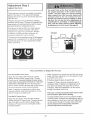
2. The Wall Control Hold push bar or button down
until the door sta_s to move.
3. _e
Key Switch or Key!ess Entry.
To open the door
When the opener is activated with the safe_
reversing sensor installed and correctly aiigned:
I /f open, the door wil_ dose.. If closed, it wiil open.
2. If closin% the door will reverse.
3. If openingsthe door will stop (allowing space for
entry and exit of pets and for fresh air)_
4 If the door has been stopped in a pa_ial_y open
_>sition, it will c_ose_
Bme_ger_
Re_
HarcJ_
5 _fobstructed while closin% the door will reverse
Manual d_sconnect
6 If obstructed while opening, the dc_orw_l_stop,
7. The garage do/or wi/_revere in the dosing cTde when
_e invisible _am is broken, ff fully c_en, the d<_r wi_
not dose When the beam is broken, "gee sensor has
no effe_ in _e opening _yde.
The toeko_ feature
prevents the troliey
from reconnecting
aatomat;caIty_ Pull the
If the sensor is not installed or r_otat gned correctly,
the door won't close from any remote control You can
c{ose the d_or with the Wall Control, hhe Key Switch,
or Key_ess Entry, however', if you activate them until
down travet is complete, if you release them too soon,
the door wili reverse.
down and back (toward
the opener} The door
can then be raised and
lowered manually as
often as necessary, To
disengage the _ockout
feature, pull the
emergency handle
The opener lights will brink for 5 seconds when the
safety revers ng sensor causes the door to reverse.
The O_ner Ughts will turn on under the following
conditions: When the opener is init aIly p!ugged in; when
the power is intemJpted; when #_e opener is activated. It
will turn off autamati_ly
after 4-112 minutes or provide
constant light when the Light feature is activated. Bulb
size is 75 wa_s maximum
Operation
Lockout
H _'_Se
position
of the Wall Contro_
Lock feature: The Lock feature is designed to
prevent operation d the door from portable remote
controls. However, the door w_I open and close
from the Detuxe Wa_t Control push bar the Key
Switch and the Multi*Function Key[ess Entry.
Press again to reverse the deer dudng the c_osing
cyc}e or to stop the door while it's opening..
Console
Re}ease
troiley will reconnect on
the next UP or DOWN
Press the _ighted push bar or button to open or
c_ose the d_r
Deluxe Lighted
The doo_ shouid be
fully dosed if possiMe_
Puli down on the red
emergency reIease
handle and lift the door
manually To
re_nnect the d@r to
the opener, press 1_he
Wal! Control push bar
or button.
(model 53824 on_y)
To activate: Press and ho_d _e Lock button for
2 seconds The push bar _[ght will flash as _ong as
the Lock feature is on.
Light feature: Press the Light button, If the opener
light is off. it w_l turn on
To turn o#: Pre_s and hoid the Lock bu_on again
for 2 seconds,The push bar _ight w_Hstop flashing.
No_a_ operation witl resume The Lock feature wi!l
also turn off whenever the SRT bu_on on the opener
end pand is activated.
_fthe opener _ight is on, (even in the 4ol,/2 minute
automat c cycle} it will turn off.
But it you use the Ught button to turn the !ight or'}
and then activate the opener, the light will turn off
after 4_l/2 minutes_
The Light button will not coet_ol the opener light
when the door is in motion,
32
Receiver
and Remote
Control
Programming
To comply wt_ F'CC Pates adiustmenl or modifications of _his
receiver _n(_/or _rar_smi_er ere prohibited e×cepl k)_' changing
the code $et_ ng or _eplacieg _he bsttery_ THERE ARE NO
OTHER USER SERVICEABLE
PARTS,
Models with 3-function remote controls: The
remote contro!(s) has been factory set to operate
with the large push button. However, you can use
either of the two smart bu_ons, if you prefen And,
the 34unction remote @ntroi(s) _n a_ activate
additional garage door openers andtor _ight controls,
Children operating
or p_aylng with a garage
door opener can injure themse|ves
or others.
The garage
door could
cfose and cause
serious injury or death. Do not allow children
tO operate the wat| push button(s) or remote
Below are instru_ions for programming your opener
to match the other buttons on your remote controls
and any additional remote controls you may
}urchase_ See availaMe accessories on page 38.
A moving
garage
doer could injure or kill
someone
under it_ Activate
the opener only
when you can see the door c|ear|y, it is free of
obstructions,
and is properly adjusted.
Models with a single4unction
remote control:
The garage door wilt operate when you press the
remote control push button. Refer to the information
betow if you _;,ant to add a 3 funclion remote cmntrol
or erase ysur programmed code.
53000SRT
Series Garage Door
(With "SRT" Bu_on)
Figure
1
S|ngle Function
Remote Control
M|R_ 3-Fan.ion
Openers
Remote_Control
Your "SRT ° garage door opener will operate with as
many as four "SRT" po_le
remote controis and
one Mufti_Function Key_ess Ent_
_o#
to _te
O_er
To Add A Remote Control
1 Se/e_ a remote contro_ push button to operate
the receiver
2. Press and hold the selected remote control push
button, Figure t.
Standard
3.oFunction Remote Control
3 Then press and release the "SR7_' button on the
back panel of the opener, Figure 2 The opener
light will flash once.
Figure
Now the opener will operate when the remote
control push bu_on is pressed.
2
Garage Door Opener
(With "SmaW' Bu_on)
If you re_ease the remote control push butlon
before the opener Hght flashes, the opener wHI
7
To Change the Selected Push Button
On the Same Remote Control
if you decide to use a different remote control button
than originally programmed into the opener, you
need to erase aNthe Iearn_ c_es and reprogram
each remote _ntrol used to operate the garage
To Erase All Remote Control Codes
, Press and ho[d the °SRT ° button on the opener
panel until the indicator light turns off (about 6
seconds). All the codes the opener has learned
will be erased.
_ND
To repro]ram, repeat Steps 1,2 and 3 for each
remote centre[ in use
Code programming
instructions
are also located
33
_AN_L
Having
Probable
operate from either
the Waft Cent,rot or
the remote control:
Cause
a ProbJem?
and Solution
1 Does the opener have electdc power? Plug a _ampinto the outlet. _tit doesn't light,
check the fuse box or Me @rcuitbreaker (Some outlets are centre/ted by a w@I switdq,)
2. Have you d sabred all d_×_rk_ks? Review installation instnsction w_onings on Page 11.
3. is there a buiid_up of Joe or snow under the door? The door may be frozen to the
ground Remove any restriction
4. The garage door spring may be broken. Have it repkaced.
5. Repeated opera£ion may have tdpped the ovedoad prote_tor in the motor. Wait
15 minutes. Try again_
!
from the remote
control_ but not from
the Wall Controh
_sthe Wail Centre//it? If not, remove the bell wire from the opener terminal screws.
Short the red and whte terminals by touching both terminals at the _sme time with a
piece of wire _fthe opener runs, cheek for a faulty wire connection at the Wall
Centre!, a short under the staples, or a broken wire.
2 Are the wiring connections correct? Review Step 6, page 18.
from the Wail Control,
but net from the
remote centre#
1. If your model has the Lock feature, make sure the lock is Off.
2. Is any wall push button flashing? Your opener needs to redeam a remote controi
cede Refer to InstnJctions on the opener p_neL
3. Does the battery test light glow when the remote control push button is pressed? _f
not, replace the bakery.
4. Program the r(xseiver to match the remote control code.
5 Repeat the receiver programming procedure with aft remote controls.
_ee remote control
1. Check the battery test light, if the light is d{m, replace the bakery
2_ Change the Iocation of the remote centre{ {r_yourcar_
3. Check to be sure. the antenna on the side or back panel of opener extends fully
downward
4. Some instailations may have sho_er range due to a meta_ door, toil backed
insulation, or metal garage siding
disturbing in tiring
quatt_,rs of homo:
If operational n_se is a problem because of proximity of the opene_ to the _iving
quarters, the Vibration iselator Kit 41 A3263 can be installed. This kit was designed to
minimize vibration to the house and is easy to install
The garage door
1. Be sure that a{I remote control push bu_ons and battery indi_'_tor !ights are off,
2 Remove the bell wire from the Wall Control terminals and operate from the remote
control on_y_If this so!yes the problem, the Wall Contrei is faulty (replace), or there is
an intermittent sho_ on the wire beb_een the Wall Control and the opener
The door doesn't
open completely:
1. If the door has been woAing propedy but now doesn't open a_i the way, increase t_he
up force. See page 29.
2. Is something obstructing the door? Remove the obstruction or repair the door_
3, if door opens at least 5 feet, the trove! limits may need to be increased
equats 2 inches of travel See page 28.
Repeat the safety reverse test after the adjustment
One turn
is complete.
Review the travel iimits adiustment procedures on page 28.
doesn't
close
Repeat the aafo_ reverse
force or down limit.
test after any adjustment
34
of door arm length, close
Having
Probable
Cause
a Problem?
(continued)
& Solution
I. tf the opener lights blink, check the safety reversing sensor, See page 23,
won't close:
2. It the opener _ights do not b_ink and: it is a new installation check the down force.
See Adjustment Step 2, page 29. For an existing installation, see below,
Repeat the safety reverse test after the adjustment
me door reveres
for
don't blink:-
,is complete;
1 Is something obstructing timed@or?Puli the red emergency retease handle. Operate
the door manua{ly. It it is unbalanced or binding, cali for professional garage doer
sewice
2, Clear armyJoe or snow from the garage floor area where the door closes.
3. Review the force adjustment procedures on page 29.
4. _fdoor reverses in the tufty ctosed posit on, decrease the travel limits (page 28),
Repeat safety reverse test a£ter a_iustments
to force or travel limits. The nc_d
for occasional adjustment of the force and limff ,settings is normal Weather
conditions in particular can affect door travel.
_e door rever_s
biiek
for
Check the safety reversing sensor_ Remove any obstruction or a_ign _he receiving eye
See page 23.
for S _ds
.... don't turn on:
Replace the light bulbs (75 watts m_imum)
bulb it regular bu{b bums out
Use a standard neck garage door opener
, , don't turn off:
/s the Light feature on? Turn it off.
The opener strains or
maximum force is
door:
The door may be out of bal&_'_;eor the spdngs are broken C_ose the d_r art_ u_> the
emergen@, televise to di_;onne_ the trolley, Open and cio_ _e d_r m_-_ual/y. A property
beJan_d d_r will stay in _y p®int of _ave_ while _ing sup_d6<l entireb/by its spdr_s. If it
d_s not_disconnect _e o_ner _nd c_/I a professional ga_@e de_r _eviceman, Do not
increase the force to o_te
t,5e o_nero
The opener motor
1 The garage door spdngs are broken, See above.
hums briefly,
won't work:
2, It the prob_ern _rs
on the first operation of the opener, dc_r may be k_kc_£ DL_sbte
the door/_k: If the chain was removed and reinstaIl_J, the motor may be out of phase.
Remove t_hechain; cycte the motor to the down _aition Obsewe the drive spr_Ket.
When _ turns in a citY, vise direction e_d stops in _ne down _s_ion, reins_!_ the ehan,
then
Repeat the safety reverse test after the adjustment
operate due to
power failure:
The chain droops
or sags:
is complete,
1, U99 the emerger>_y re}e_e to dis@nne_ iXe trolley. _r_e _@r _ _ o[_en_ a_.t cbs_S
manually W_en lf_e r_wer is restore, pre_ __e W_[ _ntrot pash _ &qd troliey wilt
automaticJy r_nned
(unle_ trolley is in _;ko_ posi_on.) See _ge 32,
2 The Emergency Key Re_ease accessory (for use on garages with no service d_r)
disconnects the trolley from outside the garage in case of power failure.
It is norma_ for the chain to droop slightly in the c!osed d_r position° Use the
emergency release to disconnect the trolley, It the chain returns to norma_ height when
the trolley is disengaged and the door reverses on a one@_ch board, no adjustments
are needed (see page 11)
35
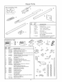
Repair
Rail AssemMy
PaNs
Pa£s
3
3
4
5
6
7
installation
tAgg5
Master
41 A3489
Compiete
link kR
1B3117
Torai_
center
183B110
Lrai/_
end sect on (each)
t_ei/ey assembly
section
83A4
4 t A3473
Chain _d
41B2616
Cabie pulley bracket assembly
NOT BROWN
cabte
4 ! A3594
Rai} assembly hardware kit (in<;_udes
hardware i_lustrat_ on page 7)
PaNs
4
3
KEY
NO.
PART
NO_
DESCRIPTION
1
2
3
4
4 !A4086,,i
41A4t66
41A4086A
41A_8i
Lighted _nsole wai controt
Lighted push bu_on wail control
Deiuxe lighted wa_l control
Singie,otune_ oh remote contro_ hous ng & screw
5
6
41A3888
41A3592
7
12
enly(nockcu_t
[_ard)
7
8
g
!0
11
12
13
I5
I6
18
19
20
10A14
29C!28
41 f,2828
217A238
12B380
12B374
41A4353
4 t A4373A
'i78B35
178B_
12B350
12_84
12_83
12£%_85
4iA3535
4tA4116
114A1903
8
3,°functiOr_remote cont_o_ housing & screw only
34unction compact remote cofltrel
housing & screw onty
Remote control visor c!ip
Emergency _ope & handle assy:
2_onductor bell wire _,,white & white/red
Door bracket
Header bracket w/Clev s pin & fastener
|
(r_eh4ng and sending eyes)
w_th 3' 2o_nductor bei/wire attache4
Cuw_ door arm sectioe
18
Square hole bracket
°C _wrap bracket
S_ot_ed bracket
NOT SHOWN
k_staHation ha_'dware bag (_ncludes hardware
illustrated
on page 7)
Safe_[y sensor hardware
Ownees manua_
36
19
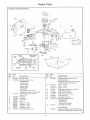
Repair Parts
Opener Assembly Pa_s
18
17
3
11
13
12
KEY
NO.
1
2
PART
NO
DESCRiPTiON
KEY
NO.
PART
NO,
tl
4t03058
Ung_e_31 replacement
motor and
bracket assemNy
Complete
with: Motoc worm° bracket,
bearing assembly, RPM sensor
12
Cover
Cover
Cover
HeI_!
RPMsensor assembly
Wire hamess assy. w/p_ug
310380
Spr_Pket cove_
41C4220A Gear and sptc_:ket a,ssy.
Complete with:
Spdng washer
_rust washer
13
41A3,474-1
41A3474_2
41A_74o5
41A2818
41A2817
Ohve gear and wom_ gear
Hei_a! gear wlretainer
and grease
Ddv¢_worm gear kit w!grease
14
15
16
4103452
41C4898A
41C4246
41B4245
Line cerd
!7
18
!9
41A2826
414JZ822A
41A4315-'7C
2O
4tA3691
Ro# pins (2}
4
5
8
7
8
9
10
41A4352
175B88
108048
30B363
30B387
30B366
1_373
41A3150
Ught s(_ket
Lens
Capacitor
Capacitor
Capac}tor
Terminal
1/2 hp
- !/3 hp
1/4 h@
b!_k
w/screws
41A2825
37
DESCRIPTION
- 1/2
_ 1/3
o 1/4
gear
h,p
h,po
h,p,
and retainer
w/grease
Iniermpter cup assy
Reviver logic board assy
Complete with:
End panel w/NI labels
End panel w/ail labels
NOT SHOWN
Opener assembly hardware kit (includes
screws not de_gnat_ by a number in illus )
Searsmode_numbersanddescriptions_
53702
53759
Requ£ed for a garage with NO
access door,
53703
53773
8 F®t Rail E_ension
53774
i0 F_t Rail Exttension:
_Tb_low a 10 fc_t _r
53709
Door Clearance
W_re4n Light Contro_:
Pfugqn Light Control:
Controls interior Iights Piugs into a
wall receptacle
53_5
Mu_ti Function
Key_ess EntPj:
Enables homeowner to operate
garage door opener from outside
by enter eg code on speeialIy
designed keyboard.
to c_en fusty,
Brackets:
Remote
Controls intedor or extedor Iights.
Wires into the electrica_ box like a
dimmer switch_
To _/ow an 8 fc>ot_x_r to c_n _dHy.
53705
Compact
With key dr_g & Velcro faster in9
Opens the garage d_sr automaScal}y
from outside when remote control is
537_
3-Function
Control:
53779
{ For Sectional Doors Om_4
3-Function Standard
Remote Controi:
Size
includes visor clip.
Replace top brackets and rollers on
door to reduce height of door travel
For use when insta_iing opener in
garage with iow headroom
clearance,
53714
For finished ceilings or where you require additional support based on garage constnJction.
Includes bracket and fastening hardware
38
index
Access
DoodOutstde
Key
Release
Aecesso_
4, 5
Chain Tension
Electrical
4, 5_ 11
Safety Warnings
2, 20, 3t
Garage Door
Testing for balance, binding and sticking
Determining high point of travel:
Secflo_l door
On@piece door
Disabling existing locks
Door cbaranee brackets (for garages with low headroom)
Force controls
Adiustment proe_ures
Problems that might require force adjustments
Safety warP_ngs
Door hardware
Mainten_ce instruction iabel
Reinforcement requirements
Removing of aH ropes
Possibie door damage
Travel Iimits
Adiustment prc_edures
Problems that might requk_ limit adiustments
Safety warnings
Manual} (Emergency)
Lc.skout feature
Manual di_onnect
3, 28, 31
12
13
3, 11
12, 38
:
4, 29
_ 35
29, 3l
3, 9, 11, 12, 18, 31,32
11 28
4, 24
3, 11
16, 24
28
34, 35
28, 31
Release Rope & Handle
32
32
Safety warnings
1 I, 19, 31,32
Wall contro_ connections
18
Safety reversing sensor connections
O_;tdoor key switch a_essoPj
connections
23
18
Sprocket noise
Vibration noise (isolator kit)
11
34
Receiver and Remote Control
Programming the receiver
Erasing a[[ codes
Activating other openers
Safe_ warning
Problems with remote control operation
33
33
33
33
Safety Reverse Test Procedure
Testing required
Safety reverse system problems
Secunng header bracket to wall
30
t t, 30, %4, 35
12
Applying excessive force on the door
Buckling or uneven floor
Safety' Warnings
User
Instruction
29
4, 5
2, 3, 9, I1.12,
Label
for garage
wall
16, 18, !9, 20, 21, 24, 28, 29, 30, 31, 32, 33
11, I8
39
i:1•
GARAGE
OWNER'S
MANUAL
DOOR OPENER
For the repair or replacement pa_s you need
Cati 7 am - 7 pm 7 days a week
Model
1 oaooo366oPART
No.
For {mhome maior brand repair service
Cali 24 hours a day, 7 days a week
t _800-4_REPAIR
For
Sears
Repair
Caii 24
the
location
of a
Service Center
in your
hours a day, 7 days a week
area
t o8OOo488-1222
For information on purchasing a Sears
Maintenance Agreement or to inquire
about an existing Agreement
CaR 9 am - 5 pm, Monday Saturday
139°53824SRT
The model numbe_
iabe! is located under
the _ight lens on the
front end panel of
your opener.
When requesting
service or ordering
pa_s, always provide
the following
s Product Type
Model Number
n Part Number
Pa_t Description
Sears,
114A1903
RoebL_ck
and Co,
@1995,
Hoffmar_
All Rights
Estates
Reserved
I_. 60179
USA_
Printed
in Mexico