1
, ,,,,,j,,,,r,,,,,,,,
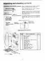
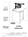
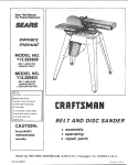
MODEL NO.
113.244400
SAW ONLY
MODEL NO.
113.244420
SAW WITH
LEGS
Serial
Number
Model and serial
number
may be found
at the right-hand
side
of the frame.
You should record both
model and serial number
in a safe place for
future use.
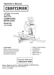
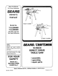
IO-/NCH MOTORIZED
CAUTION:
Read GENERAL
ADDITIONAL
and
SAFETY
® assembly
iNSTRUCTIONS
= operating
carefully
® repairparts
Sold by SEARS,
Part No. 69131
ROEBUCK
AND
CO., Ch i cage,
IL. 60684 U.S.A.
Printed in U.S,A.
_due to a defect
SEARS
you rr_y also have otherdghts
,
SEARS0 ROEBUCK AND C0.. Sea _ Tower.
2. GROUND ALL TOOLS
This toot is _quipped with an approved 3-conductor
_,x_rdand a 3_prong grounding type plug to fit the prc_.
per grounding type receptacle. The green conductor _n
the _rd
is the grounding wire, Neverconnect
the
green w_re to a |ire terminal.
3. KEEP GUARDS
in working
eBignrnent,
4. REMOVE
iN PLACE
order,
ADJUSTING
and =n proper
adjustment
and
KEYS ANDWRENCHES
Form habit of checking to see that keys and adjusting
wrenches are r_noved frorr too! before turning _ton,
5, KEEP WORK AREA CLEAN
Ctu_ered areas and benches invite accidents.
must r_t be slipperydue to wax or sawdust.
Floor
6_ AVOID DANGEROUS
ENVIRONMENT
Do_'t use power tools in damp ot wet b-._.ationsor exted. Pr_
7. KEEP CHILDRENAWAY
AJt visitors should be kept a safe distance from work
8r_,
8. MAKE WORKSHOP
KID-PROOF
-_ with padlocks, master switd-_es, or by removing
s_rter keys.
g. DON'T FORCE TOOL
It wifl do the job better and safer at the rate for which
it was des_ned.
10. USE RIGHT TOOL
Don't force tool or attachment
deigned for.
1!. WEAR
PROPER
to do a job it was not
APPAREL
Do not wear loose clothing, giovea, neckties of jewelry
(rings, wristwatches) to get caugh_ in moving parts.
NONSUP footwear is recommended.
Wear protective
hair covering to contain long hair. Rol! long sleeves
above the elbow.
12. USE SAFETY GOGGLES (Head Protection_
Wear safety goggles (must comply with ANSI Z87.1)
at all dines. "Everyday eyeglasses onty have impact re-
vary
BSC 41.3. Chicago. IL 60684
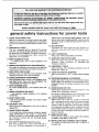
genera! safetyinstructions
1. KNOW YOUR POWER TOOL
Read and =_nderstand the owner's manual and labels
affixed to the tool Learn its app|ication and thnita[ions
as we_! as the s_ecific potential hazards peculiar to this
tool
which
for power
tools
sistant lenses, they are NOT safety glasses:' Also. use
face or dust mask if cutting operation is dusty, and ear
protectors (ptugs or muffs} dudng extended periods of
operatior_.
33. SECURE WORK
Use ¢|a_ps or a vise to hold work wr_en practical It's
_ier than using your hand. frees both hands to oper
ate tool
14. DON'T OVERREACH
Keep proper footing and balance at al! times
15. MAINTAIN
TOOLS WITH CARE
Keep tools sharp and dean for best and safest performance.
Follow
instructions
for lubricating and
changing accessories,
16. DISCONNECT
TOOLS
before servicing; when changing
blades, bits, cutters, etc.
accessories
such as
17. AVOID ACCIDENTAL
STARTING
Make sure switch is in "OFF" _osition before plugging
in=
18. USERECOMMENDED
Cortsult the owner's
ACCESSORIES
manual for recommended
acces-
..........s°ries-F°ll°WThe
the
use,instructi°nsof
improperthatacceseoriesaCC°mpanYmaythecauseaC"
hazards,
19. NEVER STAND ON TOOL
Serious inlury could occur if the tool is tipped or }f the
cutting tool is accidentally contacted.
Donor store materials above or near the tool such that
it is necessary to stand on the tooJ to reach them.
20. CHECK DAMAGED
PARTS
Before, further use of the tool, a guard or other part
that is damaged should be carefully checked to ensure
that it will operate properly anc_ perform its intended
function, Check for alignment of moving parts, binding
of moving ;)arts, breakage of parts, mounting, and any
other conditions that may affect its operation. A guard
or other part that is damaged should be properly r_
paired or replaced.
21. DIRECTION
OF FEED
Feed work into a blade or cutter against the direction
of rotation of the blade or cutter only.
22. NEVER LEAVE TOOL RUNNING
UNATTENDED
Turn power off. Don't leave tool until it comes to a
complete stop.
additional
safety
instructions
Safety is a combination of operator common sense and
alertness at all times when the band saw is being used.
h. When cutting a large piece of material,
it is supported at table height,
Safety Instructions
2. Getting
To Know
3. Basic
Band Saw
4. Maintenance
5. Stability
for Power
Your Band
j.
Operation ..................
...............................
16
t. Use caution when cutting off round rnateria_ such
as dowel rods, or tubing. They have a tendency/ _o
rol_ whiie being cut causing the b_ade to 'bite".
Always use a "V" block, o_ ctamp round materia!
to a miter guage.
17
18
of Machine,
Your band saw must be bolted secureiy to a stand or
work bench. In addition, if there is any tendency for
the band saw to tip over or move during certain op
erations such as cutting long heavy boards, bolt your
band saw stand or workbench to the floor.
,
Do not feed the matedal too fast while cutting.
Only feed the material fast enough so thaz the
blade witl cut, Keep fingers away from the blade.
k, Use citation when cutting off materia_ vvh;ch is
irregular in cross section ,which couid pinch the
blade before the cut is completed.
A piece of
motding for exampte must lay fiat on the tab!e and
not be permitted to rock while being cut.
PAGE
Toots.,.
2
Saw ............
m,
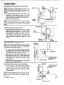
When backing up the workpiece,
the btade may
bind in the kerf (cut),..
this is usually caused by
sawdust clogging
up the kerr or because the
blade comes out of the guides. If this happens:
1°
Turn off the band saw.._ remove ptug
power source outlet.,,
remove cover
band saw. Insert a screwdive_ or wedge
kerr _.. rotate the wheels by hand while
ing up the workpiece,
Location
This
band
saw
is intended
for indoor
use only.
7. Protection: Eyes, Hands, Face, Ears, Body
a Wear safety goggles that comply with ANSI Z81.1
and a face shield if operation is dusty. Wear ear
plugs or muffs during extended periods of operation. Do not wear gloves,.,
roll long sleeves
above the elbow.
b,
Do not cut pieces of materia! too small to hold by
hand.
C.
Avoid awkward
hand positions where a sudden
slip could cause a hand to move into the blade,
f,
o, Never operate band saw with cover removed.
p. Do not perform layout, assembly, or setup
on the table while the cutting tool is rotating.
work
q, Turn saw "off" and remove plug from power supply outlet before installing or removing an acces=
sory or attachment,
°
Should
any
part of
this
band
saw
be
missing,
or fail in any way, or any electrica_
component
perform
properly,
shut off power
switch
and
Make sure the blade runs downward toward the
table. Always adjust tracking wheel correctly so
that the blade does not run off the wheels.
Always
from
from
in the
back-
n. Never leave the band saw work area with the
power on, before the machine has come to a complete stop, or without removing and storing the
switch key,
d. Never turn your band saw "ON" before clearing
the table of all Objects (tools, scraps of wood,
etc.) except for the workpiece and related feed or
support devices for the operation planned.
e_
make sure
i, Hold the work firmiy against the table:
WARNING:
FOR YOUR OWN SAFETY,
DO NOT
ATTEMPT
TO OPERATE YOUR BAND SAW UNTIL
IT iS COMPLETELY
ASSEMBLED
AND INSTALLED ACCORDING
TO THE INSTRUCTIONS..
_AND
UNTIL YOU READ AND UNDERSTAND
THE FOb
LOWING:
1. General
for band saw
plug
from
missing,
rich.
power
andJor
supply
failed
outlet.
parts
before
Replace
bend,
fail to
remove
damaged,
resuming
opera-
adjust blade tension correctly.
9,
g- ALWAYS adjust the upper blade guide and blade
guard to just clear the workpiece to protect the
operator, to keep btade breakage to a minimum,
and to provide maximum support for blade,
i i ii,
i
i, , i
Think Safety,
Safety is a combination
of operator common sense
and alertness whenever the band saw is in operation.
10, This band saw _s not designed
to cut metal
ii ii
WARNING:
DO NOT ALLOW FAMIUARITY
(GAINED FROM FREQUENT
USE OF YOUR BAND SAW} TO
BECOME
COMMONPLACE.
ALWAYS
REMEMBER
THAT A CARELESS
FRACTION
OF A SECOND
IS
SUFFICIENT TO iNFLICT SEVERE INJURY.
i _1,
safety instructions
for band saw
The operation of any power tool can result in foreign
objects being throwr; into the eyes, which can result in
severe eye damage, Always wear safety goggles complying with ANSI Z87.1 (shown on Package) before
commencing power t0ol operation. Safety Goggles are
available at Sears retail or catalog stores.
READ AND FOLLOW THE INSTRUCTIONS APPEARING ON THE INSTRUCTION PLATE ON
THE FRONT OF THE BAND SAW.
MOTORIZED
BAND
SAW
INCH
...........
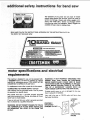
motor specifications
requirements
This machine
a 1725 RPM
volts, 60 Hz.,
CONVERTED
is designed to use, and is equipped with,
motor. It is wired for operation on 110-120
alternating current. (TOOL MUST NOT BE
TO OPERATE ON 230 VOLT).
TO POWER
SUPPLY
OUTLET
This machine must be grounded while in use to protect
the operator from electric shock.
Plug power cord into a 110-120V properly grounded
type outlet protected by a 15-amp. time delay or CircuitSaver fuse or circuit breaker.
If you are not sure that your outlet is properly
have it checked by a qualified electrician.
J
and eJectrJcaJ
For replacement motor refer to parts list in this manual.
CONNECTING
_L
WARNING: IF NOT PROPERLY GROUNDED THIS
POWER TOOL CAN CAUSE AN ELECTRICAL
SHOCK PARTICULARLY WHEN USED iN DAMP
LOCATIONS CLOSE TO PLUMBING. IF AN ELECTRICAL SHOCK OCCURS THERE IS THE POTENTIAL OF A SECONDARY
HAZARD SUCH AS
YOUR HANDS CONTACTING THE SAW BLADE.
If power cord is worn or cut, or damaged in any way,
have Jt replaced immediately.
Your unit is for use on 110-120 volts, and has a plug
that looks like below.
3-PRONG
PLUG
grounded,
WARNING: DO NOT PERMIT FINGERS TO TOUCH
THE TERMINALS OF PLUGS WHEN INSTALLING
OR REMOVING THE PLUG TO OR FROM THE
OUTLET.
PROPERLY
GROUNDED
_PRONG OUTLET--_
GROUNDING
PRONG
motor specifications
requirements
and electrical
This power toot is equipped with a 3-conductor cord
and grounding type plug which has a grounding prong,
approved by Underwriters' Laboratories and the Canadian Standards Association. The ground conductor has
a green jacket and is attached to the tool housing at
one end and to the ground prong in the attachment
plug at the other end.
This plug requires a mating 3-conductor grounded type
outlet as shown.
ff the outlet you are planning to use for this power tool
is of the two prong type DO NOT REMOVE OR ALTER
THE GROUNDING
PRONG IN ANY MANNER. Use an
adapter as shown below and always connect the
grounding lug to known ground.
It is recommended that you have a qualified electrician
replace the TWO prong outlet with a properly grounded
THREE prong outlet.
An adapter as illustrated is available for connecting
plugs to 2-prong receptacles. The green grounding
tug
extending from the adapter must be connected to a permanent ground such as to a properly grounded
outlet
box.
NOTE: The adapter illustrated is for use only if you already have a properly grounded 2-prong receptacle.
Adapter is not allowed in Canada by the Canadian Electrical Code.
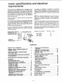
The use of any extension cord will cause some loss of
power. To keep this to a minimum and to prevent overheating and motor burn-out, use the table below to determine the minimum wire size (A.W.G.) extension cord.
Use only 3 wire extension cords which have 3-prong
grounding type plugs and 3-pole receptacles which accept the tools plug.
Extension
MAKE
SURE THIS
IS -_
KNOWN GROUND
CONNECTED
TO A \
RECEPTACLE
.@
GROUNDING
1
/
Wire Size
Cord Length
A.W.G.
LUG
ADAPTER
I / 3PRONG
Up to 100 Ft.
100 - 200 Ft.
200 - 400 Ft.
16
14
10
/
CONTENTS
POWER TOOL WARRANTY ...................
2
GENERAL SAFETY INSTRUCTIONS FOR
POWER TOOLS .............................
2
ADDITIONAL SAFETY iNSTRUCTIONS
FOR BAND SAW ............................
3
MOTOR SPECIFICATIONS AND ELECTRICAL
REQU IREMENTS ............................
4
UNPACKING
6
AND CHECKING CONTENTS .....
ASSEMBLY
Assembling Steel Legs .......................
Mounting
Band Saw on Leg Set ..............
Mounting
Band Saw to Workbench ...........
Installing the Table ..........................
Installing the Blade .........................
Tracking
the Blade .........................
Adjusting
the Table Square to Blade .........
Adjusting
Guide Bar ........................
Adjusting
Front to Back Squareness .........
Adjusting Side to Side Squareness ...........
Adjusting Upper Blade Guide
Assembly
................................
Adjusting
Upper Blade Guides ...............
Adjusting
Upper Thrust Roller ...............
7
8
8
9
9
11
12
!2
13
13
14
14
14
Adjusting
Assembly
Adjusting
Adjusting
Adjusting
GETTING
Lower Blade Guide
................................
Lower Blade Guides ...............
Lower Thrust Roller ...............
Table ............................
TO KNOW
YOUR
BAND
SAW
Tension
Adjustment
Knob ..................
Tension
Setting ............................
Guide Bar Lock Screw ......................
Thrust Roller Adjustment ...................
Table Lock Knob ...........................
Tilt Scale ..................................
Blade Guides ...............................
On-Off Switch ..............................
BASIC
BAND
SAW
14
15
15
15
16
16
16
16
16
16
16
16
OPERATION
Sawing ....................................
Blade Selection
Guide ......................
17
17
MAINTENANCE .............................
Lubrication .................................
18
18
RECOMMENDED
18
ACCESSORIES .............
TROUBLESHOOTING
REPAIR
........................
PARTS .............................
19
20
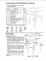
and checking
contents
Model 113.244400
Band Saw is shipped complete
one carton 10ut DOES NOT INCLUDE Steel Legs.
in
Model 113.244420 Band Saw is shipped
one carton and iNCLUDES Steel Legs,
in
complete
Separate all oarts from packing
materials and check
each item with illustration and "Table of Loose Parts".
Make certain atl items are accounted for, before discarding any packing
If any parts are missing, do not attempt to assemble the
band saw, plug in the power cord, or turn the switch on
until the missing parts are obtained and installed correctly.
#2 PHILLIPSSCREWDRIVER
INCH WRENCH
material.
COMBINATION
SQUARE
MUST
BE TRUE
STRAIGHT
EDGE OF
BOARD 3/4" TH1CK
EDGE MUST BE
PERFECTLY STRAIGHT
DRAW LIGHT
LINE ON BOARD
ALONG
I!
LJ
!
SHOULD
SQUARE
BE NO GAP OR OVERLAP HERE WHEN
IS FLIPPED OVER IN DOTTED POS|TION
TABLE
OF LOOSE
PARTS
QTY.
,=
J
C
A
B
C
D
Basic saw assembly ..................
Owners Manual ......................
Saw Table ..........................
Blade, Saw 1t4 .......................
E
Bag Assembly Part - # 69132 Containing
the following parts:
Roller, Blade Thrust ...................
Switch, Key .........................
Nut, Wing 1/4-20 .....................
Screw, Truss Hd. 1/420 x 1............
Washer 17/64 x 5/8 x 1/16 .............
Insert, Table ..........................
Screw, Hex Hd, 5I! 6-18 x 3/4 ..........
External Lockwasher, 5/16 .............
Wrench, Hex "L" 5!32 .................
1
1
1
1
2
1
I
t
1
1
2
2
1
THE FOLLOWING PARTS ARE iNCLUDED WITH
MODEL 113.244420 ONLY.
J _
_tem
A
B
C
D
E
F
G
H
J
€$
Nut, Hex Head 112-t3 ...............
Nut, Hex 1/4-20 ....................
Screw, Truss Hd. 1/4-20 x 518........
Lockwasher, 1/4 External .............
Fore, Levering ......................
Leg ...............................
Channel, Support ...................
Stiffener, Side .....................
Stiffener, End ......................
HARDWARE
K
L
M
N
_._----
FOR MOUNTING
/
F
TOOL
4
4
4
4
in Loose Parts Beg Part No. 69097
assembly
.EX.OT
LOCKWASHER
SCREW%=
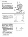
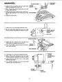
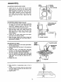
ASSEMELi NG STEEL LEGS
1. Assemble the two (2) End Stiffeners and the two (2)
Side Stiffeners
using four (4) 1t4-20 Truss head
screws. The End Stiffeners are placed on top of
..........
_.
"--.,.,__
_
_l
______...... _j
___J
t
_
SiDE
each Side Stiffener as shown. Insert screws through
the 9/32 inch diameter holes and attach Iockwashers
STIFFENER_
CHA"NEL
wrench.
4. Install teveling feet as shown.
loosen nut on inside of leg and
to raise or lower feet. Adjust
necessary, and then tighten nuts
levelers
are not
LEG
To level Leg Set,
turn nut on outside
all four levelers, if
on inside of leg.
intended
for
"/
/
LEGS_
!
/
height
7
-----
_,__
r'___'_-_._
SUPPOR:r" ', _"-'_---_ _
_[
i _/_CHANNEL
LOCKWASHER __'_-_
SUPPORT
HEX NUT_
l
3. Remove the four (4) Truss head screws which were
SCREW
!
assembled in Paragraph No. One. Place the two (2)
_,.
!._..;
Support
Channels
shown,
in position,
holes
in supports
with as
holes
in the
Stiffeners,alignreplace
Iockwashers and nuts. Tighten all nuts using 7/16"
END
SIDE STIFFENER!
and 114-20nuts and finger tighten nuts.
2. Attach the four (4) legs to the Side and End Stiffeners using 1t4-20 screws, Iockwashers and nuts as
shown.
NOTE: These
adjustment.
J
8
28
28
28
4
4
2
2
2
Screw, Hex Hd. 5/16-18 x 1..........
* Lockwasher Ext. 5/16 ................
Nut, Hex 5/16-18 ...................
Washer 11/32 ID ....................
Parts Contained
_
QW.
Description
LEG
SCREW
"_
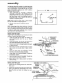
assembly
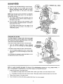
MOUNTING BAND SAW ON LEG SET
This leg set is included with Model No. 113.244420
only.
NOTE: For illustrative purposes, the Band Saw is
shown mounted on the Craftsman Catalog No. 9-22236
Steel Leg Set. If leg set is purchased separately, the
motor support is not needed with this band saw.
1. Remove the Band saw cover by releasing 5 latches.
CHECK BOLTS
FOR
TIGHTr
NOTE: Check the bolts which hold the feet to the Band
Saw as shown. Make sure they are tight.
LEFT
2. Place the Band Saw on the Steel Legs, position as
shown, and align the mounting holes in the feet of
the Band Saw with those in the END STIFFENERS
(marked with an X in the illustration).
O
©
OO
© Ooo
3. Mount saw to legs using four 5/16-18xl u hex head
screws, Iockwashers, and hex nuts. Tighten screws
and nuts using 1/2 " wrench.
_O
©
O
O
MOUNTING BAND SAW TO WORKBENCH
If band saw is to be used in a permanent location, it
should be fastened securely to a firm supporting surface such as a workbench or accessory leg set (922236).
If mounting to a workbench, holes should be drilled
through supporting surface of the workbench using
dimensions illustrated.
1. Each leg should be bolted securelyusing 5/16 " diameter machine screws, Iockwashers,and 5/16 " hex
nuts. Bolts must be of sufficient length to accomodate legs of saw, washers, hex nuts, and thickness
of supporting surface.
2. Locate and mark holes where band saw is to be
mounted.
3. Drill (4) 11t32"dia. holes through workbench,
4. Remove band saw cover by releasinglatches.
5, Place band saw on workbench aligning holes in feet
with holes drilled in workbench.
6. Insert and tighten all four screws.
5"
__
DIA, (4)
, HOLES
12½ _
©
assembly
An alternate method of mounting is to fasten band saw
to a mounting board, The board should be of sufficient
size to avoid tipping of saw while in use: Any good
grade of plywood or chipboard with a 3/4" minimum
thickness is recommended.
1. Follow instructions
for mounting
to workbench,
substituting
a board 18" x 24" minimum size and
using 5116 inch flat head screws, Iockwashers, and
hex nuts. Screws must be of sufficient
length to
accomodate
legs of saw, washers, hex nuts, and
thickness of supporting board.
NOTE: Holes must be counter sunk so screw
are flush with surface of supporting board.
2. Securely
clamps.
clamp board to workbench
heads
using C
24' MIN.
J
18" MBN.
!
5"
. (4)
HOLES
12½"-----_
NOTE: Supporting surface where band saw is mounted
should be examined carefully after mounting to insure
that no movement during use can result. If any tipping
or walking is noted, secure workbench,
legs, or supporting surface before operating band saw.
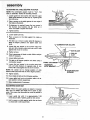
iNSTALLiNG
THE TABLE
Apply a coat of automobile wax to the table and inside
surfaces of trunnion that slide on frame.
1.
Loosen the guide bar lock screw and position the
upper guide assembly all of the way up. Tighten
lock screw.
2.
Locate two (2) 5/16 - 18 x 3!4 inch hex head screws
and external Iockwashers among loose parts.
3.
Position trunnion at the 0 degree
en table lock knob.
4.
Place table on trunnion so that the slots in trunnion
line up with the mounting holes in table as illustrated.
5.
Insert hex head screw and Iockwasher
through
front hole of trunnion into table and tigntan.
6.
Loosen table Lock Knob and position
the 45 degree position.
Trunnion
7.
Insert hex head screw and Iockwasher
hole of trunnion into table and tighten.
through
8.
Return table to the 0 degree
table lock knob.
and tighten
iNSTALLING
mounting
position
screws
__..
TABLE'--'_
_._TRUNN,ON
position and tight-
at
rear
THE BLADE
1. Loosen the two
blade guard.
TO iNSiDE
SURFACES
mAPPLY
WAX
and remove
the
2. Loosen the guide bar lock screw and position the
upper guide assembly approximately
two inches
above the table as shown and tighten the lock
screw.
--TABLE
LOCK KNOB
EXTERNAL
_P
_
,,,o °?2Wx"S"22
assembly
SCREWS
BLADE GUIDES-_
3. Loosen the two cap screws that lock upper blade THRUST
guides and separate them about 1/8 _.
\
ROLLER _
.
4. Find a Thrust Roller among loose parts and insert
in upper guido assembly.
_
5. Loosen two hex head screws in upper guide assembly and slide assembly all of the way back in the CAP
slots.
6. Tighten hex head screws,
7. Loosen lock nut on thrust roller adjustment screw.
J
8. Back out thrust roller adjustment screw by turning
counter clockwise using 5/32 inch setscrew wrench.
JST ROLLER
ADJUSTMENT
SCREW
BLADE GUIDES ___
9. Loosen the two capscrews that lock the lower
_____'_//_#
blade guides and separate them about 1/8".
_
10. lower
Find aguide
Thrustassembly.
Roller among loose parts and insert in THRUST
ROLLER _
_"_
'
__
i
LOCi( NUT--
11, Loosen lock nut on thrust roller adjustment screw,
12. Back out'thrust
roller adjustment screw by turn=ng
counter clockwise using 5/32 inch setscrew wrench.
J
13. Loosen inner and outer lock nuts on lower guide
assembly adjustment.
14. Turn Iocknuts clockwise and move
assembly back to the fTame tube.
lower
--THRUST
ROLLER
ADJUSTMENT
SCREW
guide
OUTER
LOCKNU1
LOCK NUT
10
p/---FRAME
TUBE
assembmy
15. Carefully
uncoil the blade holding
it at arms length.
16. Place the blade over the wheels with the teeth
pointing downward
toward the table as shown.
Make sure the blade is in the center of the rubber
tires.
WASHE
INDICATOR
NOTE: Your band saw can be used with 1/4 or 3/8 inch
wide blades, 72 5/8 inches long. A 1/4 inch blade is
included with this saw.
17. Turn tension adjustment
knob clockwise until the
large washer lines up with the tension indicator on
the inside of the cover.
18. Turn the upper wheel by hand clockwise
a few
turns and notice if the blade remains in the approximate center of the tires.
If the blade moves away from the center of the
wheels while you are turning it, the blade is not
TRACKING properly.
CENTERED
ON TIRES
OFBOTH
WHEELS
TRACKING
THE BLADE
The Motor Bracket is hinged which allows the upper
wheel to be tilted so that the blade can be TRACKED.
By turning the Tracking Adjustment
Screw, the upper
wheel will be tilted (see illustration).
MOTOR
If the blade moves toward the front of the band saw:
a.
BRACKET---_
TRACKING_
ADJUSTMENT
SCREW
Turn the tracking adjustment screw clockwise
about 1/4 of a turn, as though you were tightening
it.
If the blade moves toward the back of the band saw:
a.
Turn the tracking adjustment screw counter clockwise about 1/4 of a turn as though you were loosening it,
Turn the screw just enough to cause the blade to run in
the approximate center of both tires,
REAR
FRONT
'
.........
ii
i,
NOTE: IF BLADE CANNOT BE MADE TO RUN IN THE APPROXIMATE
CENTER OF THE
MAY BE NECESSARY TO REPOSITION THE UPPER WHEEL ON THE MOTOR SHAFT.
1.
LOWER
WHEEL,
Loosen the set screw in the upper wheel
a.
If the blade is running to the front of lower wheel
b.
If the blade iS running to the rear of lower whee! - Slide upper wheel to the front away from the motor,
2.
Tighten
the set screw
3.
Track the blade by turning the tracking
- Slide upper wheel to the rear toward the motor.
in the upper wheel.
adjustment
screw in or out as needed.
1!
IT
ADJUSTING THE TABLE SQUARE TO BLADE
NOTE: The combination square must be "true".
start of "assembly" section for checking method.
Sea
1. Loosen guide bar lock screw and raise the upper
blade guido assembly all the way up.Tighten guide
bar lock screw.
2. Place a square on the table against the rear edge of
the blade as illustrated.
3. If adjustment is required, loosen the two screws in
the trunnion stop brackets and tap table up or
down until table is square with blade.
4. Tighten screws.
5. Loosen table lock knob,
6. Place a square on the table against the blade as
illustrated.
7. Tilt table up or down to align table 90 degrees to
blade (0 degree position) and tighten table lock
knob.
8, Loosen the two screws in the trunnion stop brackets and slide bracket under lock knob until it rests
against end of slot in trunnion,
9, Tighten
_INATION
SQUARE
scr_ews.
10. Check squareness of blade to table. Make readjustments if necessary.
11. Loosen table lock knob.
12. Tilt table to 45 degree position and check using a
combination square,
TABLE LOCK KNOB
13, Loosen the two screws in the trunnion stop brackets and slide bracket on opposite side of lock
knob until it rests against end of slot in trunnion.
NOTE:
Be careful
not to
change
position
of slide
STOP BRACKET
SCREWS
bracket under lock knob that set the 0 degree position.
!4. Tighten screws.
15. Check blade to table at the 45 degree position.
16. Loosen table lock knob and position table at O de=
gree position;recheck squareness.
17. Make readjustmentsif necessary.
ADJUSTING
GUIDE BAR
NOTE Wh n "
'
:
e the upper guiaes are raised or lowered,
they must not deflect the blade front to back or sideways. This means that the guide bar must be parallelto
_'_
rt____/_
I_'_
,nches
above
tab,e
T,,htan
guide
bar
,ock
scrow
////Y/_
_///_._/_/_//_j_J
12
_
Itl _fl
the blade,
1. Lower guide bar until it is approximately 1-3/4
2. Hold a square on table against guide bar as shown
to check side to sde squareness,
"
./_(,
"_---
_
__._
___._.___._______X__\
1
assembmy
3. Hold square on table against guide bar as shown to
check front to back squareness.
NOTE: Square must rest on the guide bar and not on
the upper guide bracket. Note illustration.
ADJUSTING
FRONT TO BACK SQUARENESS
NOTE:
When
making
adjustments,
guide bar lock
screw must be loosened. To check squareness it must
be tightened.
a.
b.
c.
GUIDE
BRACKET
ADJUST_
SCREWS
Loosen guide bar lock screw and lower guide bar
until it rests on table. Leave lock screw loose.
Loosen two hex head screws on the top of frame
tube.
Loosen lock nuts on guide bar bracket adjustment
screws.
HEAD
SCREWS
DE BAR
BRACKET
LOC_
NOTE: Turning guide bar bracket adjustment screws
clockwise will move quide bar toward front of saw.
Turning screws counter clockwise will move guide bar
to rear of saw.
d.
e.
f.
g,
h.
Turn guide bar bracket adjustment screws !/4 turn
using 5/32 inch set screw wrench.
Tighten hex head screws on top of frame tube,
Raise guide bar 1-314 inches and tighten guide bar
lock screw.
Check squareness. Readjust if necessary.
Hold guide bar bracket adjustment
screws with
5/32 inch set screw wrench and tighten lock nuts.
m
ADJUSTING
HEAD
SCREWS
SiDE TO SIDE SQUARENESS
NOTE: When making adjustments, guide bar lock
screw must be loosened. To check squareness it must
be tightened.
IIIDE BAR
BRACKET
a.
Loosen guide bar lock screw and lower guide bar
until it rests on table. Leave lock screw loose.
b. Loosen two hex head screws on top of frame tube.
c. Grasp guide bar as illustratedand move m the side
needed to square it with table. This will slide the
guide bar bracket into position.
d. Tighten hex head screws on the top of frame tube.
e, Raise guide bar 1-3/4 inches and tighten guide bar
lock screw.
f.
Check squareness,Readjust if necessary.
!3
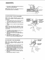
ADJUSTING
UPPERBLADEGUIDEASSEMBLY
HEX
GULLET--x4
@o S
placed.
1. Loosen two hex head screws in upper blade guide
assembly and slide assembly forward in the slots
until the front edge Of the blade guides are approximately 1132"from the GULLET of the saw blade.
0
E
2. Tighten two hex head screws.
NOTE: It may be necessaryto back out thrust relier adjustment to allow thrust roller to move back from blade
to get 1/32"
guide.
clearance
ADJUSTING
UPPER
UPPER
BLADE
THRUST
BLADE
moves toward the blade and almost touches.
" by hand,
2. While turning the upper w hee clockw=se
adjust the thrust roller until it barely touches the
blade and starts to rotate. Now move the roller
back slightly until it stops rotating while upper
wheel is rotated.
3. Tighten lock nut while holding thrust
ment screw with setscrew wrench.
BLADE
CAP
GUIDE
THRUST
ROLLER "-7
_
/
Z
/
Z
Z
/
"j
/
_ Fr_ j
0
-[c_J']
_
[=_
_
LOCK NUT
O
|
GUIDE
relier adjust-
_---TH RUST ROLLER
ADJUSTMENT
SCREW
APPROX.
ASSEMBLY
1/32"
1. Turn lock nuts on lower blade guide assembly
counter
clockwise and move lower blade guide
assembly forward until the front edge of the blade
guides are approximately 1132" from the GULLET
of the saw blade.
THRUST ROLLER
ADJUSTMENT
EW
NOTE: It may be necessary to back out thrust roller adjustment
to allow thrust roller to move back from the
blade to get 1/32" clearance from the gullet to edge of
blade guide.
2. Tighten
GUIDE
ROLLER
ting, the rollers should stop rotating.
1. To be sure the thrust roller is properly supporting
the blade, turn the thrust roller adjustment screw
using 5132 " setscrew wrench so that the roller
LOWER
"'"--_"_"'-"--
GUIDES
NOTE: The thrust rollers support the blade from the
rear and will rotate when the blade is pushed against
them while you are cutting. As soon as you stop cut-
ADJUSTING
/,
from the gullet to edge of blade
1. Loosen the two cap screws that lock the upper
blade guides and press the two guides evenly
against the sides of the blade but do not pinch the
blade. Release the guides and rotate the upper
wheel slightly clockwise moving the blade downward. Make sure one guide is not further away
from the blade than the other. Tighten both cap
screws.
ADJUSTING
FRONT
EDGE----/
lock nuts.
GU LLET
!4
LOCK
NUTS
assembUy
SAW
ADJUSTING
BLADE
GUIDES
SCREWS
BLADE
LOWER BLADE GUIDES
1. Loosen the two cap screws that lock the lower
blade guides and press the two guides evenly
against the sides of the blade but do not pinch the
blade. Release the guides and rotate the upper
wheel slightly clockwise moving the blade downward. Make sure one guide is not further away
from the blade than the other. Tighten both cap
....
screws.
ADJUSTING LOWER THRUST ROLLER
1. To be sure the thrust roller is properly supporting
the blade, turn the thrust roller adjustment screw
using 5/32" setscrew wrench so that the roller
moves toward the blade and almost touches.
THRUST ROLLER
ADJUSTMENT
2. While turning the upper wheel clockwise by hand,
adjust the thrust roller until it barely touches the
blade and starts to rotate. Now move the roller
back slightly until it stops rotating while upper
wheel is rotated.
__SCREW
3. Tighten lock nut while holding thrust roller adjustment screw with setscrew wrench.
4. Rotate the upper wheel a few times by hand and
check the blade guides and thrust rollers. Make readjustments if necessary.
-THRUST
TRUSS
HEAD
ADJUSTING THE TABLE
1. Replace the blade guard on the upper guide assembly and tighten screws.
2. Locate the table insert and place it in the opening in
the table.
3. Locate a 114 - 20 x 1 "truss head screw, a flat washer, and a 1/4 - 20 wing nut among loose parts. Insert screw into hole in table top as illustrated.
4. From the underside of the table, install washer and
wing nut onto the truss head screw and tighten
finger tight. This will keep the table flat and in
alignment.
5, Replace the cover.
GUARD
SCREW=-_
6. Blade should be in approximate center of slot in
insert.
7. If blade runs to one side, loosen hex head screws
that mount table to trunnion and shift table to center blade in table insert.
8. Tighten screws.
7777
JJJJJ
15
ROLLER
SCREWS
3
2
TENSION SETTING
(BNSIDE)
1
DN ADJUSTMENT
KNOB---_
COVER RETAINING
CLiP (5 USEDJ
8
ON-OFF SWITCH
\
3
GUIDE BAR
LOCK SCREW
\
GUARD
7
BLADE
GUmDES
8
TILT
SCALE
BLADE
GUIDES
4
UPPER THRUST
ROLLER ADJUSTMENT
|
4
LOWER THRUST
ROLLER ADJUSTMENT
5
TABLE LOCK KNOB
FRONT
BACK
1.
TENSION
ADJUSTMENT
KNOB .... Tightening
the knob will increase the tension on the blade,
Loosening it willdecrease the tension,
2.
TENSION
SETTING...
The marking indicates the
correct blade tension for the blade. For example,
when installing the blade, tighten the tension ad-
5.
ring.
TABLE LOCK KNOB...
Turning the knob allows
the table to be tilted and locks it in place.
justment knob until the indicator washer is pointing
to the marking on the inside of cover.
6.
TILT SCALE...
GUIDE BAR LOCK SCREW...The
upper blade
guides should just clear the workpiece while cutting. Always adjust the upper guide assembly and
lock the guide bar by tightening the guide bar lock
screw before turning on the band saw.
7.
BLADE GUIDES...
Supports the blade and keeps
it from twisting during operation. An adjustment is
necessary when blades are changed or replaced.
ON-OFF SWITCH...
See below and next page.
3.
4.
8.
THRUST
ROLLER
ADJUSTMENT...Turning
the adjustment screw moves the thrust roller in or
out to support the blade from the rear while cut-
Shows degree table is tilted.
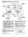
ON-OFF SWITCH
The On-Off Switch has a locking feature. THIS FEATURE IS INTENDED TO PREVENT UNAUTHORIZED
AND POSSIBLY HAZARDOUS USE BY CHILDREN
AND OTHERS.
1.
pULL ON
Insert key into switch.
I
NOTE: Key is made of yellow plastic,
r//
/
16
/
./
getting
to know
your band
2.
To turn machine on, insert finger under switch
and pull end of switch out.
3.
To
turn machine
PUSH leverUNATTENDED
in.
NEVER
LEAVE OFF...
THE MACHINE
UNTIL IT HAS COME TO A COMPLETE
STOP.
4.
To lock switch in OFF position.., hold switch IN
with one hand.., REMOVE key with other hand.
saw
lever
f
p_LL0_
I
[_
PULL
WARNING: FOR YOUR OWN SAFETY, ALWAYS
LOCK THE SWITCH "OFF" WHEN MACHINE iS
NOT IN USE ... REMOVE KEY AND KEEP iT BN A
SAFE PLACE... ALSO... iN THE EVENT OF A
POWER FAILURE [ALL OF YOUR LIGHTS GO OUT}
TURN SWITCH OFF... REMOVE THE KEY AND
STORE iT REMOTE FROM BAND SAW. THaS WiLL
PREVENT THE MACHINE
FROM STARTING UP
AGAIN WHEN THE POWER COMES BACK ON,
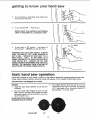
basic band saw operation
A band saw is basically a "curve cutting" machine. It is also used for straight-line cutting operations such as crosscutting, ripping, mitering, beveling, compound cutting, and resawing. It is not capable of doing inside cutting.
This band saw is not designed
to cut metal
SAWI N G
.
1.
Adjust the upper guide assembly
workplece.
to just clear the
2.
Use both hands while feeding the work into the
blade. Hold the workpiece firmly against the table.
Use gentle pressure, and do not force the work, but
allow the blade to cut.
The smallest diameter circle that can be cut out is
determined by the width of the blade. For example,
a 1/4" wide blade will cut a minimum diameter of
approximately 1-1/2": (See Chart)
BLADE SELECTION GUIDE FOR
MINIMUM CIRCLE CU'I'rING
BLADE SIZE
3t8"
1t4"
17
ntenance
WARNING:
FOR YOUR OWN SAFETY, TURN
SWITCH
"OFF"
AND
REMOVE PLUG FROM
POWER OUTLET BEFORE MAiNTAiNiNG
OR
LUBRICATING YOUR BAND SAW.
BLACK
TIRES
Pitch and sawdust that accumulate on the tires should
be removed witha
stiff brush or scraped off with a
piece of wood. Do not use a sharp knife or any kind of
solvent.
When the tires become worn they should
When
replacing
the tires, stretch them
wheels but do not glue them on.
be replaced.
around the
m
MOTOR
GENERAL
Keep your Band Saw clean,
Remove sawdust from the inside.
Do not allow pitch to accumulate on the table, blade insert, blade guides, or tl_rust rollers. Clean them with
Craftsman Gum and Pitch Remover,
Apply a thin coat of autornobile-Wpe
wax on the table
so the wood slides easily while cutting. Also apply wax
to the inside surfaces of the trunnion.
MOTOR
Frequently
motor.
vacuum or blow
out any sawdust from the
If the power cord is worn, cut, or damaged in any way,
have it replaced immediately.
LU BRICATION
All of the BALL BEARINGS are packed with grease at
the factory. They require no further lubrication.
RECOMMENDED
ACCESSORIES
Item
Cat. No.
Floor Base................................
Miter Gauge..........................
Rip Fence................................
Blades................................
Steel Leg Set. ............................
Circle Cutting Attachment ...................
Table Extension ...........................
Power Tool Know How Handbooks
Radial Saw ................................
Table Saw.................................
9-22213
9-22574
9-23433
See Catalog
9-22236
9-24301
9-24302
9`2917
9-2918
The above recommended accessories are current
and were available at the time this manual was
printed.
18
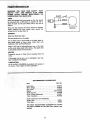
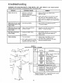
troubleshooting
WARNING:
FOR
YOUR
OWN
SAFETY,
TURN
SOURCE OUTLET BEFORE TROUBLESHOOTING
PROBABLE
TROUBLE
Motor
"OFF"
AND
REMOVE
PLUG
FROM
POWER
YOUR BAND SAW.
CAUSE
REMEDY
1. Defective On-Off switch.
Defective switch cord.
Defective switch box receptacle.
2. Motor Defective,
1. Replace defective
Band Saw again.
1, Not tracking properly.
1. Adjust tracking, see Assembly
"Tracking the Blade."
Blade does not run in thei
approximate
center of the
lower wheel.
1. Upper wheel not positioned
correctly on shaft.
1. Reposition the wheel, see Assembly
Section, "Tracking the Blade."
Band Saw slows down
when cutting.
1. Cutting too small a radius.
1. Stop feeding, and back up to the material
slightly, until the band saw speeds up.
2. Replace blade.
Blade
wiB not run.
SWITCH
does not run in the
approximate center of the
upper wheel.
2. Dull blade.
B_ades breaking.
1. Too much tension.
2. Kink in blade caused by cutting
too small a radius or turning the
material too fast when cutting,
parts before using
2. Consutt Sears Service. Any attempt to repair
this motor may create a HAZARD unless
repair is done by a qualified service technician.
Repair service is available at your nearest Sears
Store.
Section,
1. Adjust tension. See Getting To Know
Your Band Saw "Tension Setting".
2. Use correct cutting technique. See Basic
Band Saw Operation Section.
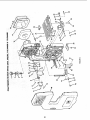
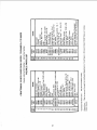
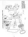
FIGURE 1
SUPPUED WITH MODEL 113.244420
Key
No.
!
2
2
4
5
7
8
11
12
J
Part No.
I
i
62614
60314
STD541025
STD551225
68060
68059
62615
STD541050
803835
69097
HARDWARE
STD523110
STD551131
STD541231
STD551031
Description
Leg
t'Screw
Truss Hd. 114-20 x 5iB
t_Nut Hex 1t4-20
t*Lockwasher,
1/4 External
Channel, Support
Stiffener, Side
Stiffener, End
t'Nut,
Hex Hd. 1/2-13
t Foot, Leveling
*Bag of Loose Parts
FOR MOUNTING
TOOL
t'Screw,
Hex Hd. 5/1618
1"*Lockwasher Ext. 5/! 6
)'*Nut, Hex 51!6-18
T'Washer 11!32 ID
x 1
" Standard Hardware item - May Be Purchased Locally
1"Al! Parts Contained In Loose Parts Bag
12
a
11
tl
19
._....-._
/
L
/
/
2O
,
! \_
c_
S
.=
o
oO
_J
03
c
o
E
_3
L
o_
_0
oo
0
E
"6
E
r_j
E
C_
I
E
=
(,3
OJ
>,
_o
-r
E==
.._ "r"
crJ
21
_o
_
ww
_w
@
\
N
_J
\
\
\
\
j ®i_
22
i
_
i_ i
'
_
i
X
e_
X
o_
W
_11,0
'
x
Off)
0
I_._(_
C)
_
_-C_
X"O,-
_
_
._--'_
F
_4
o _Z
_x:
,-,m
_o
_J
c_._.,-
€€%
I
8
0
CX:
o,)
i
0
E
O_-
_b
E
{o
r_
a,)
oo
LO
Z_
X
oO
m
,...
x
_
00
_
__
X
"0
Z
x_
_E_
ooc_
x_
_
6
O-
Co
z
_
..'r,
X
.__v_z_a:
_
0
_("J
_
_I_ _._
m:_ on"
-
_
_
_
o _.- c o o o._e3
_
_
6_
E_8
-r
p_
23
E
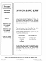
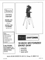
Sears
10JNCH
SERVICE
Now
that
should
ply
have
a need
contact
Roebuck
MODEL NO=
you
SAW
purchased
ever
any
exist for repair
Sears
Service
and Co. stores.
facts when
your
10-inch
parts
Center
Band
Saw
or service,
sim-
and
most
Be sure to provide
Sears,
all pertinent
you call or visit.
113,244400
SAW ONLY
MODEL NO.
The
model
found
number
of your
10-Inch
on a plate at the right-hand
Band
Saw
will
be
side of the saw.
113.244420
SAW WITH LEGS
WHEN
ORDERING
FOLLOWING
PART
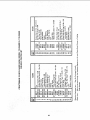
HOW TO ORDER
REPAIR PARTS
REPAIR
PARTS,
ALWAYS
GIVE THE
INFORMATION:
NUMBER
MODEL
PART DESCRIPTION
NAME OF ITEM
NUMBER
10-Inch Band Saw
113.244400
or
113.244420
All
parts
Center
not
listed
may be ordered
and most
stocked
transmitted
Sears
locally,
to a Sears
stores.
your
from
If the
order
Repair
will
Parts
any
Sears
parts you
be
Service
need
are
electronically
Distribution
Center
for handling.
Sold by SEARS,
Part No. 69131
ROEBUCK
AND
CO., Chicago,
Form No. SP4557-3
IL. 60684 U.S.A.
Printed
in U.S.A.
7/83