1
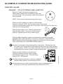
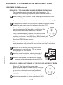
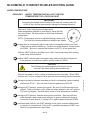
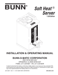
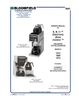
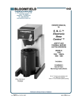
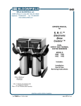
SERVICE BULLETIN
607.002
WELLS BLOOMFIELD, LLC
2 ERIK CIRCLE, P. O. Box 280 Verdi, NV 89439
telephone: 775-689-5707
fax: 775-689-5976
www.wellsbloomfield.com
TO:
FROM:
SUBJECT:
Bloomfield Authorized Service Agencies
Tony Nixon, National Service Manager
Troubleshooting 1016BVM
June 26, 2007
Model 1016BVM brewers utilize electronic control boards for timing and
power switching functions. While it is tempting to immediately replace
these electronic components in the case of equipment malfunction, they
are, in fact, generally quite reliable and are seldom the root cause of the
problem. Learning the unique characteristics of these controllers will help
the service technician diagnose problems and return units to service more
efficiently.
IMPORTANT SERVICE
INFORMATION
We have recently experienced a high number of warranty claims where
the probe and both boards have been replaced. It is highly unlikely that
all three parts would fail simultaneously. Tests of returned boards and
probes show a very high percentage to be non-defective.
Any board found not to be
defective will be returned to
you.
This brewer incorporates several features that render strictly intuitive
troubleshooting ineffective:
•
Unit is equipped with a high wattage heating element coupled with
programmed action to insure rapid temperature recovery. The heater
is energized near the start of a brew cycle and remains energized until
the water inlet solenoid is de-energized. Water supply volume and
pressure during the brew are critical. Insufficient water volume during
a brew will allow the heater to boil available water, causing the unit to
overheat. Symptoms include very little water dispensed during a
brew, a general fault (all lights flashing) and/or tripped hi-limit safety.
•
With traditional mechanical thermostats it is common procedure to
adjust settings during a brew. This is not possible with this control
board. Programming examines water temperature when it receives
a brew signal, and brew cannot start until water is at the setpoint
temperature. So that a brew is not interrupted by the influx of cold
water, once a brew is initiated, programming does not look at tank
temperature again until brew is completed. Neither setpoint, brew
time nor dripout time may be adjusted during a brew.
Control boards, power boards
and temperature probes
submitted for warranty will be
tested.
Warranty costs, including
labor and associated
expenses, will NOT be
credited for replacing
non-defective items.
Attached is a comprehensive troubleshooting guide for your use in
diagnosing problems with this brewer. We fully expect that use of this
guide will eliminate unnecessary replacement of good parts, as well as
improving technician knowledge of, and comfort level with, this equipment.
SvcB 607.002 Rev. B
1 of 10
080313
cps
BLOOMFIELD 1016BVM WIRING DIAGRAM
WHITE
REAR
WARMER
FRONT
WARMER
RED
15
17
WHITE
16
BLUE
1
KEYPAD
HEAT
POWER
BREW
CANCEL
ON
OFF
2
3
WARMERS
MAIN
FRONT
REAR
BLUE
WHITE
1
CONTROL
BOARD
11
7
RED
BREW
INLET
SOLENOID
10
POWER BOARD
NEUTRAL IN
12
VALVE B
TEMPERATURE
PROBE
3
WHITE
HEATER B
5
VALVE A
BLACK 12 ga.
BROWN
4
LINE IN
HEATER A
GND
+5VDC
WPLATE 1
WPLATE 2
2
WPLATE 3
1
HI-LIMIT
BLACK
12 ga.
L1
N
9
MAIN
WARMER
14
L2
FUSE 10A
8
WHITE
G
13
3-WARMER
AUTOMATIC BREWER
MODEL 1016BVM
VOLTS
120/240
ref. dwg# 73641
PHASE
WATTS
1
3800
TERMINAL
STRIP
L1
N
G
L2
POWER CORD (WHEN USED)
2 of 10
Service Bulletin 107.002
ORANGE
HEATING
ELEMENT
WHITE 12 ga.
RED 12 ga.
BLACK 12 ga.
4
BLOOMFIELD 1016BVM TROUBLESHOOTING GUIDE
SCOPE: This Troubleshooting Guide addresses potential problems peculiar to this specific
brewer. Normal maintenance issues, such as wiring damage and lime/calcium build-up are
not covered.
DESCRIPTION: Bloomfield model 1016BVM is a displacement-style decanter coffee brewer
that incorporates electronic control of brew temperature and brew time
Electronic components include a membrane keypad with LED indicator lights; a circuit
board that controls water temperature and brew time functions; and, a circuit board
for power switching functions. Water temperature is sensed by a thermistor immersed
in the hot water tank.
Electro-mechanical components include an electrically actuated water inlet solenoid,
an electrical resistance water heater and three independently switched electrical
resistance plate warmers.
Preliminary Inspection:
Be sure brewer is connected to a potable cold water supply line and water is turned on.
Be sure brewer is connected to appropriate electrical supply and circuit is turned on.
CHECK tank is filled
Press ON OFF key until all indicators are off.
Be sure brew chamber is installed, then place empty decanter under brew head.
Press BREW BREW BREW CANCEL. BREW and HEAT indicators will flash
and tank will begin filling. When water begins to flow from brew head,
press ON OFF key to terminate fill.
Service Bulletin 107.002
EXPECTED (NORMAL) OPERATION
Press ON OFF key. POWER and HEAT indicators should glow.
HEAT indicator will go out when water in tank is at setpoint temperature.
Press BREW key to initiate a brew.
NOTE: Brew will not begin until water temperature is up to setpoint.
BREW indicator glows until brew plus dripout is completed. Main warmer is energized
automatically and LOWER warmer indicator glows. At end of brew, plus dripout, three
beeps sound and BREW indicator goes out.
Press WARMER key to energize or de-energize a warmer plate. The associated
WARMER indicator glows when energized.
TABLE OF CONTENTS
DIAGNOSTICS
Flashing lights and beeping alerts .............................................................................
BREW TIME & VOLUME
Too little brew volume (short pot) ...............................................................................
Too much brew volume or brews continuously ...........................................................
Brew light remains on for too long past end of brew .................................................
WATER TEMPERATURE
Water temperature too low or no heat .......................................................................
Water temperature too high or runaway ....................................................................
WARMER PLATES
Main warmer does not heat .......................................................................................
2
4
5
5
6
7
8
page 1 of 8
3 of 10
BLOOMFIELD 1016BVM TROUBLESHOOTING GUIDE
DIAGNOSTICS - FLASHING LIGHTS AND BEEPING ALERTS
All LEDs flashing: GENERAL FAULT
Possible causes are a shorted temperature probe, an over-temperature condition,
or controller did not detect at least 2ºF temperature rise within 4 minutes.
Press CANCEL for 6 seconds to reset after a general fault.
IMPORTANT: Be sure brewer has sufficient inlet water volume. Low volume will
allow water in tank to boil, resulting in possible over-temperature shut-down.
Allow unit to cool and complete tank fill procedure before attempting a reset.
TEST 1: Disconnect probe from control board and press CANCEL for 6 sec. to reset.
IF unit resets, probe is defective. Replace probe p/n 83644. Be sure to replace seal
washer p/n 83731 at the same time.
IF unit does NOT reset, or returns to fault within 4 minutes, proceed to next test.
TEST 2: Connect a known good temperature probe to control board. Reset unit.
IF unit will not reset, replace control board p/n 83635.
IF HEAT LED lights, but unit returns to fault, proceed to next test.
.
CAUTION
The following procedure exposes live electric circuits.
Use due care when working around electricity.
TEST 3: Check for line voltage at heating element terminals.
gaskets p/n 8043-30.
IF voltage is NOT present, proceed to next test.
CAUTION
The following procedure exposes live electric circuits.
Use due care when working around electricity.
TEST 4: Be sure hi-limit thermostat is reset. Check for line voltage at power board
terminals LINE IN and NEUTRAL IN.
IF voltage is present, replace power board p/n 83636.
4 of 10
page 2 of 8
Service Bulletin 107.002
IF voltage is present, replace heating element p/n 8716-1. Also, be sure to replace
BLOOMFIELD 1016BVM TROUBLESHOOTING GUIDE
DIAGNOSTICS - FLASHING LIGHTS AND BEEPING ALERTS
TEST FOR NORMAL OPERATION ON INITIAL START-UP
When power is first applied to the brewer, all LEDs will come on momentarily and alert
beeps four times.
The alert will beep once each time a key is pressed.
Press BREW BREW BREW CANCEL to initiate tank fill. BREW and HEAT LEDs flash
continuously. Press ON OFF to terminate fill.
Press ON OFF to energize brewer. Alert beeps five times and POWER and HEAT LEDs
on steady. HEAT LED goes off when water reaches setpoint temperature.
Pressing BREW key during a brew or before HEAT light goes out will cause BREW LED
to flash. A second brew will not be initiated.
Press CANCEL at any time during a brew to de-energize the water inlet valve.
NO lights and NO sound:
Be sure brewer is plugged into an appropriate receptacle and circuit breaker for that
circuit is turned on.
Check/reset hi-limit thermostat.
Service Bulletin 107.002
Check multi-wire cable from control board to power board. Cable must be properly
connected to both boards.
CAUTION
The following procedure exposes live electric circuits.
Use due care when working around electricity.
IF
Check for line voltage at power board terminals LINE IN and NEUTRAL IN.
voltage is present and no lights/sound, replace power board p/n 83636.
NO lights, alert beeps on startup but no beep on keystroke:
Check ribbon cable from keypad to control board. Cable must be properly connected.
IF cable is properly connected, test keypad by connecting a new keypad to control
board. Replace keypad p/n 83633 if found defective.
page 3 of 8
5 of 10
BLOOMFIELD 1016BVM TROUBLESHOOTING GUIDE
BREW TIME & VOLUME
PROBLEM 1 - TOO LITTLE BREW VOLUME (SHORT POT)
Remove 2” silver hole plug from brewer body.
Water solenoid open time is controlled by upper dial
on control board. Be sure pointer on dial is set to desired
time in seconds.
40 50
30
60
20
70
80
10
205
SOLENOID TIMER
(WATER VOLUME)
(SECONDS)
2
3
200
4
OFF
185
195
190
WATER TEMP
( ºF )
NOTE: Time cannot be adjusted during a brew cycle.
8
7
5
6
BREW SIGNAL TIMER:
- BREW LIGHT
END OF BREW BEEPER
(MINUTES)
Brewer must be installed on a water line with average
pressure of at least 20 PSI. Be sure water supply is connected
to brewer, and that water supply valve is fully open. Be sure any in-line filters are
clean and functioning properly.
FILTER
SCREEN
Shut off water supply to unit. Remove solenoid cap
and clean filter screen. Be sure to reinstall screen
properly. Reinstall cap and turn on water supply.
WASHER
INLET
FITTING
CAP
Using a reliable stopwatch, measure actual brew time against time on dial.
Set dripout time (lower right dial on controller) to minimum. Press BREW key.
BREW indicator will glow and relay on power board will click. At end of brew
cycle, three beeps sound and BREW indicator goes out.
IF brew time is acceptable, check water path for obstructions. Silicone hose from
inlet valve may be removed from tank fitting and directed to an empty decanter
to verify volume. NOTE: once tank is filled, any volume of water entering tank
will displace a like volume of water through the brew head.
1
IF brew time cannot be adjusted, or timing is outside of
useable range, replace control board p/n 83635.
VOLUME
CONTROL
JUMPER
IF volume remains too low even though brew timer may be adjusted and no
blockages can be found, replace water inlet solenoid p/n 85752.
6 of 10
page 4 of 8
Service Bulletin 107.002
Examine jumper at bottom of control board.
If jumper is across both pins, remove jumper
and reinstall on right pin only. This sets timing
range to 120 - 250 seconds.
BLOOMFIELD 1016BVM TROUBLESHOOTING GUIDE
BREW TIME & VOLUME (continued)
PROBLEM 2 - TOO MUCH BREW VOLUME OR BREWS CONTINUOUSLY
Tank temperature must not exceed local boiling temperature. Set
no higher than local boiling temperature (based on altitude) minus 5ºF.
IF water is boiling in tank, Remove 2” silver hole plug from brewer body lower
water temp setting.
Brewer must be installed on a water line with pressure of no more than 90 PSI.
IF If water pressure exceeds 90 PSI at anytime, a pressure regulator must be
installed in water supply line to limit pressure to less than 90 PSI.
Remove 2” silver hole plug from brewer body. Inlet solenoid
open time is controlled by upper dial on control board. Be
sure pointer on dial is set to desired time in seconds.
40 50
30
60
20
70
80
10
SOLENOID TIMER
(WATER VOLUME)
(SECONDS)
205
2
3
200
4
8
OFF
Using a reliable stopwatch, measure actual brew time and
compare to time on dial. Set dripout time (lower right dial on
controller) to minimum. Press BREW key. BREW indicator will
glow and relay on power board will click. At end of brew cycle, three beeps
sound and BREW indicator goes out.
185
195
7
5
6
BREW SIGNAL TIMER:
- BREW LIGHT
END OF BREW BEEPER
(MINUTES)
190
WATER TEMP
( ºF )
Silicone hose from inlet valve may be removed from tank fitting and directed to an
empty decanter to verify volume. All flow from hose must stop at end of brew
cycle.
IF brew time of 120 seconds is too long, move volume
1
control jumper to cover both pins. This will reduce
timing range to 60 - 180 seconds.
IF brew time cannot be adjusted, or timing is outside of
Service Bulletin 107.002
useable range, replace control board p/n 83635.
IF brew time is acceptable, but flow continues or hose
continues to drip, replace inlet solenoid p/n 85752.
VOLUME
CONTROL
JUMPER
PROBLEM 3 - BREW LIGHT REMAINS LIT FOR TOO LONG PAST END OF BREW
Remove 2” silver hole plug from brewer body.
Brew signal time (dripout) is added to end of brew cycle.
This is to allow time for water remaining in brew chamber
to drip out as coffee before a new brew is initiated.
Be sure pointer on dial is set to desired time in minutes.
40 50
30
70
80
10
205
SOLENOID TIMER
(WATER VOLUME)
(SECONDS)
2
3
200
4
OFF
185
195
190
NOTE: Time cannot be adjusted during a brew cycle.
60
20
WATER TEMP
( ºF )
8
7
5
6
BREW SIGNAL TIMER:
- BREW LIGHT
END OF BREW BEEPER
(MINUTES)
IF dripout timer cannot be set, replace controller p/n 83635.
page 5 of 8
7 of 10
BLOOMFIELD 1016BVM TROUBLESHOOTING GUIDE
WATER TEMPERATURE
PROBLEM 1 - WATER TEMPERATURE WILL NOT CONTROL
TEMPERATURE TOO LOW OR NO HEAT
IMPORTANT
Energizing the brewer without water in the tank will usually cause the
hi-limit to trip, and can permanently damage the heating elements.
Remove 2” silver hole plug from brewer body.
Water temperature setpoint is controlled by lower left dial
on control board. Be sure pointer on dial is set to desired
temperature.
40 50
30
60
20
70
80
10
205
SOLENOID TIMER
(WATER VOLUME)
(SECONDS)
2
3
200
NOTE: Temperature cannot be adjusted during a brew cycle.
Turn dial fully counterclockwise to disable tank heater.
4
OFF
185
195
190
WATER TEMP
( ºF )
8
7
5
6
BREW SIGNAL TIMER:
- BREW LIGHT
END OF BREW BEEPER
(MINUTES)
IF temperature is consistently high or low, remove temperature probe from tank.
Clean calcium and lime build-up. If probe cannot be cleaned, replace probe
p/n 83644. Be sure to replace seal washer p/n 83731 at the same time.
Observe HEAT indicator, and listen for a “click” from power relay while turning
water temp. dial clockwise.
IF neither HEAT indicator glows nor power relay clicks as the dial is advanced
from minimum to maximum, replace control board p/n 83635.
CAUTION
The following procedure exposes live electric circuits.
Use due care when working around electricity.
Remove top panel to check voltage at heating element terminals. When HEAT
indicator is lit, full line voltage must be present across heating element terminals.
element p/n 8716-1. Also, be sure to replace gaskets p/n 8043-30.
IF voltage is NOT present, remove front panel. Be sure hi-limit thermostat is not
tripped. Press red button until it clicks and stays latched in the “set” position.
If hi-limit has tripped, find and rectify cause of over-temperature condition.
IF voltage is NOT present, examine wiring and connectors. Be sure multi-wire
cable between control and power board is in good condition and properly
connected to both boards. If wiring is OK, replace power board p/n 83636.
IF unit heats and controls, but HEAT indicator never lights, examine ribbon cable
connector at control board. If this is OK, membrane keypad p/n 83633 may
need to be replaced (non-critical item).
8 of 10
page 6 of 8
Service Bulletin 107.002
IF voltage is present at element terminals and unit is not heating, replace heating
BLOOMFIELD 1016BVM TROUBLESHOOTING GUIDE
WATER TEMPERATURE (continued)
PROBLEM 2 - WATER TEMPERATURE WILL NOT CONTROL
TEMPERATURE TOO HIGH OR RUNAWAY
Remove 2” silver hole plug from brewer body.
Water temperature setpoint is controlled by lower left dial
on control board. Be sure pointer on dial is set to desired
temperature.
40 50
30
60
20
70
80
10
205
SOLENOID TIMER
(WATER VOLUME)
(SECONDS)
2
3
200
4
OFF
185
195
190
WATER TEMP
( ºF )
NOTE: Temperature cannot be adjusted during a brew cycle.
Turn dial fully counterclockwise to disable tank heater.
8
7
5
6
BREW SIGNAL TIMER:
- BREW LIGHT
END OF BREW BEEPER
(MINUTES)
Check that temperature probe is properly connected to control board.
An open or disconnected probe will not control.
Temperature will runaway until the high-limit safety trips.
IMPORTANT
A shorted probe will cause a GENERAL FAULT condition
where all functions are disabled and all indicators flash.
Press and hold CANCEL key for 6 seconds to reset after
a general fault condition.
Brewer may also be reset by disconnecting from
electrical power, then reconnecting.
1
CONNECT TEMP
PROBE HERE
Measure resistance of temperature probe with an ohmmeter:
Probe should read approximately 31.5k at room temperature (70ºF)
and 2.5k at brew temperature of 200ºF. Any reading less than 1k
indicates a defective temperature probe.
IF temperature probe fails resistance check, replace probe p/n 83644.
Service Bulletin 107.002
Be sure to replace seal washer p/n 83731 at the same time.
IF temperature probe passes resistance check, and is properly connected,
replace control board p/n 83635.
For a runaway condition:
Be sure unit has sufficient water supply. Check probe as above.
IF HEAT indicator is on, regardless of position of water temp dial on control board,
replace control board p/n 83635.
IF unit continues to heat, even when HEAT indicator is not lit, replace
power board p/n 83636.
page 7 of 8
9 of 10
BLOOMFIELD 1016BVM TROUBLESHOOTING GUIDE
WARMER PLATES
PROBLEM 1 - MAIN WARMER DOES NOT HEAT
Main warmer plate will energize automatically at start of a brew. Plate may also
be energized by pressing LOWER WARMER key. LED above LOWER key will
glow when warmer plate is energized.
CAUTION
The following procedure exposes live electric circuits.
Use due care when working around electricity.
Remove front panel. Check for voltage between power board terminal WPLATE1
and terminal block L2 (white wire).
IF voltage is present, check warmer plate fuse. Fuse is located in lower right corner
of power board bracket. Remove fuse and check for continuity. If fuse is bad
(no continuity/infinite ohms), examine warmer wiring and element for obvious
damage. Locate and repair cause of short before replacing fuse p/n 83164.
IF voltage is present and fuse is OK (continuity/zero ohms), replace warmer element
p/n 8572-18.
IF voltage is NOT present and warmer light is lit, be sure wiring and connectors are
in good condition, then replace power board p/n 83656.
Service Bulletin 107.002
page 8 of 8
10 of 10