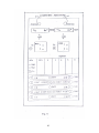
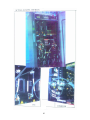
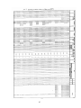
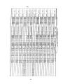
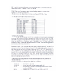
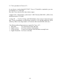
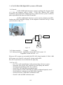
1
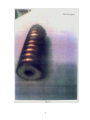
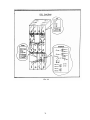
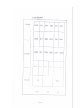
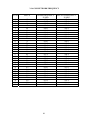
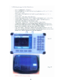
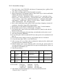
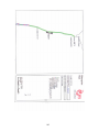
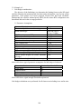
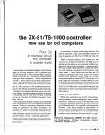
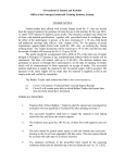
Chapter 3
77
3-1.1 Some important abbreviations frequently in use of GSM network:Sr.no.
1
2
3
4
5
6
7
8
9
10
11
12
13
14
15
16
17
18
19
20
21
22
Abbreviations
GSM
MS
BSS
BTS
BSC
MSC
HLR
VLR
ETSI
IMSI
LAC
NCC
OMC
SIM
BCC
MNC
RT
MRIF
PG
ARFCN
MSIDN
MSRN
Long forms
Global System for Mobile Communication
Mobile Station (Handset)
Based Station Sub System
Base Transceiver Station
Base Station controller
Mobile Switching Center
Home Location Register
Visitor Location Register
European Telecom Standard Institute
International Mobile Subscriber Identity
Location Area Code
Network Color Code
Operation and Maintenance Center
Subscriber Identity Module
Base Color Code
Mobile Network Code
Radio Terminal
Mini Rack Interface
Peripheral Group
Absolute Radio Frequency Channel No.
Mobile Sub’s ISDN No
Mobile Sub’s roaming no.
3-1.2 General: 1.
2.
3.
4.
Up link: - 890-915 MHz and Down link: - 935-960 MHz
GSM Bandwidth: - 25 MHz
Channel Bandwidth: - 200 KHz
No. of Channels 25 x 106
------------ = 125
200 x 103
Numbers of 124 Channels are available and spread at 200 KHz intervals.
First carrier not used due to interference to other systems.
5. ARFCN Up link Frequency
= 890 + 0.2 x N (N-CHL No. 1-62)
Down link Frequency = 935 + 0.2 x N (N- CHL No. 63-124)
6. Pl. see block schematic of GSM network in Fig. 3-3 and Lucent BTS front view in
Fig. no. 3-2, 3-4, & 3-5.
78
79
80
81
82
83
84
85
86
3-1.5 METERS REQUIRED FOR BTS A/T INCLUDING INFRASTRUCTURE:1. SMPS:1) Power Factor Meter
2) Insulation Tester
3) Psophometer
4) DC Load
7) Clip-on meter
5) Digital Multimeter
6) Thermometers
2. Battery:1) Thermometers
2) Multimeter
3) DC Load
4) Shunt and Clip-on meter
3. DG:1)
2)
3)
4)
5)
6)
7)
Earth Megger with cranker (old) or digital (Earth Tester) Make: - WACO
500V Insulation Tester.
Thermometer
A/C load
Tacho meter (for RPM) for conventional / for 15 KVA not applicable.
Voltmeter/ Ammeter (Clip-on Meter)
Spirit level. 8) Noise level meter
4. BTS:1) Through watt Meter: - (Trans Power only) Make: - Radarf for
- It is a Analogue meter to be operated with 50 Ω Heat sink Termination.
Type: - 3551 with 12048 Directional Watt Meter.
- Sl no. 2806 Through Watt meter. VXL technologies Ltd Faridabad.
400 - 1000 MHz 50 W to read middle scale.
- Bird through Watt Meter Model no. APM-16 with 25, 50, 100 W Knobs.
(All will read RT/TRE Power in watt directly.)
2) Bird Antenna Tester :- ( VSWR only) 806 – 960 MHz.
3) Site Master Make Anritsu: Models - S113 B (5-1200 MHz)
- S114 B (5-1200 MHz) + 100-1200 MHz spectrum analysis.
- S331 B (25-3300 MHz)
- S332 B (25-3300 MHz) + 25-3300 MHz spectrum analysis.
- S331 B Model called Insta Cal Module and it is to be calibrated with OSL
method. (Open, Short, Load)
Bird Site Master (Bird Electronics Corporation)
Models – SA 1700 EX, 25-1700 MHz No power measurement.
- SA 1700 EXP ----do----------with -----do--------.
- SA 2500 EX, 780-2500 MHz------do-------.
- SA 6000 EX, 25-6000 MHz-----do-------.
4) Digital Multimeter.
5) Laptop 6) RF cords 7) Spirit level. 8) Earth tester
5. TOWER:1) Theodolite (Digital)
2) Earth Tester
3) Torque wrench
4) Digital Camera
5) Binocular
87
3-1.6 GSM NETWORK FREQUENCY
Sl. No
ARFCN
1
2
3
4
5
6
7
8
9
10
11
12
13
14
15
16
17
18
19
20
21
22
23
24
25
26
27
28
29
30
31
63
64
66
67
68
69
70
71
73
74
75
76
77
78
80
81
82
87
88
111
112
113
115
116
117
118
119
120
122
123
124
TRANS FREQUENCY
IN MHz
947.6
904.7
948.2
948.4
948.6
948.8
949.0
949.2
949.6
949.8
950.0
950.2
950.4
950.6
951.0
951.2
951.4
952.4
952.6
957.2
957.4
957.6
958.0
958.2
958.4
958.6
958.8
959.0
959.4
959.6
959.8
88
RECEIVE FREQUENCY
IN MHz
902.6
902.8
903.2
903.4
903.6
903.8
904.0
904.2
904.6
904.8
905.0
905.2
905.4
905.6
906.0
906.2
906.4
907.4
907.6
912.2
912.4
912.6
913.0
913.2
913.4
913.6
913.8
914.0
914.4
914.6
914.8
3-1.7 GSM BTS A/T (Lucent)
General:The GSM network started in Western zone by January 2002 with Lucent
switch. All over India GSM network is covered by several switches like,
East zone : - Nortel
West zone: - Lucent, Alcatel
North zone: - Motorola
South zone: - Motorola, Erickson, Nokia.
The GSM network in India is to be followed in phase’s as below:Phase i: Lucent
Phase ii: - Configuration enhancement by Lucent.
Phase iii: --------Phase iv: - Alcatel 1 M. 4.5 L. Equipment + management
Phase iv +:- ITI
3 M 13.5 L Equipment + management
Phase iv ++:- ITI
2 M 6.5 L. Swap sites W/O Tower
First time in Maharashtra, Lucent A/T was started by September 2002 and
Swapping of Lucent BTS started by Dec 2004. Here A/T of both Lucent and Alcatel BTS
is explained. Please see figure 3.3 for Trunking diagram of GSM network .
BTS A/T comprises of 1) Infrastructure A/T which mainly includes SMPS, Battery, DG
and Tower.
2) BTS equipment A/T
3) 15 GHz M/W system.
4) Coverage A/T.
Before proceeding for BTS A/T:-
Obtain TT-0 as well as check offer in ATOM, Whether all relevant
information particularly Power plant and its adequacy is correctly filled or
not?
Obtain approved layout of equipment room duly signed by DET ( Incharge )
Get site configuration chart which is very useful to know site name, ID,
configuration, cell ID, NCC, BCCH, BCC, Longitude, latitude, ARFCN
and LAC, Specification.
Note down type of BTS i.e. BSNL/ Non BSNL, Swap or New, or
Redeployment?
If BTS is installed in Tele. Exchange then you have to fill up all
information about PP i.e. SMPS, Battery and E/A , make, capacity, total
load of Exchange including BTS, and it is adequate or not ?
If BTS is installed on existing tower then ask for A/T report of tower and
if a tower is new then conduct tower A/T.
N.B. - Sample configuration chart is attached here. Pl. see chart no. 3-1.3 and 3-1.4 for
Lucent / Alcatel BTS.
89
BTS A/T started:Note that the following tests are deleted from the Test schedule.
1. Trans frequency ,
2. Check of feeder cable loss,
3. Check of frequency stability,
4. Check of C/I,
5. Spurious and harmonics.
Vide letter no, TD/NT-GSM-Vol ii -----Dated 14.10.2003.
Check of infrastructure:-
Earth measurement: - Ask for Earth value record. How much and when
measurement was taken, get the details. Also measure the Earth value
for Exchange as well as tower. Limit :- 0.5 Ω
Antistatic flooring: - Many sites it is observed that antistatic floor is
provided but not connected to earth through 5W/ 1 MΩ resistance. In
some stations copper strip is available but not connected to earth.
Verify the provision of Fire Detection and alarm system, Fire fighting
equipment, and Emergency light arrangement
Check Location, Alignment, as per the approved layout plan and Rigidity
of BTS Bay by shaking the Bay.
Check the status of Power plant and battery if existing, also note down
the peak hour load of the exchange.
Check the status of existing E/A.
Hardware check of Equipment:- As per the specification and purchase order, note and confirm No of Rack,
Rack serial no, no of sectors and thereby no of RTs installed per sectors.
- Note down sector wise Cell ID and ARFCN.
- Write SACFA clearance no as per record.
- Note down no. of TDMA channels, (Eight), LAC, NCC, and BCC.
- Write down all details of Tower and point out the discrepancies.
- Verification of iron work:- As per layout drawing check following items
with respect to cabling and wiring.
• Positioning of equipment
• Leveling of Rack by spirit level
• Quality of RF conectorisation
• Crimping of cables
• Grounding of feeder cable, Rack, DDF,
• Sealing of Feeder cable connection.
- Note down the tilting of Antennas and spacing between the sectors.
- Check the availability of tools, necessary spare modules, and documents
of BTS .
Confirm Q/A report of Power plant, Battery if existing or new. On Lucent BTS there is
no Q/A stamp as it is supplied by vendor
90
Before starting BTS A/T lock BTS site i.e. all the 3 sectors from OMC-R .Put off the
Rack. Again restart and check that all Hardware getting restored or not?
Initialization: - Proceed as follows,
- Connect LCT to BTS at MRIF -2 (Mini Rack Interface) which is in the
Bottom of BTS Rack by RS-232 cable.
(One end USB port and other end 9 pin serial port).
- Open CMA -2000, click RBT -2000,
- File- Eqpt- configuration- Software load- Hardware test.
Files- New or load, if BTS is new then write some file name for example A/T test,
Eqpt. - Create BTS type- Micro cell OD12- ABIs type- DMCS.
GSM type- 900- edit component - BTS rack is displayed on screen of LCT.
Open configuration- 4.4.4 (Standard mode)
Set standard- Select all BTS- Rack contents of 4-4-4 configuration- O.K
Click RBT-2000- Files- equipment- Configuration- Central configurationO and M slots as Cell 1
- 31 slots
Antenna type - 1 or 2
Cell 2
- 30 slots
Cell 3
- 29 slots (all are default values)
PTT/ PCM setting,
Link configuration- BSC
Link type – E1
Clock configuration- 2 MB / GPS O.K
Cell configuration- Feeder cable loss Power reduction from 0 to 26 dB – O.K
Alarm editor – Select alarm as active low or active high
Check LCD – Passed/ Fail- O.K
Check Equipment- auto command for equipment check- EPROM assess – read or write.
Read – Checks all internal connections between all components in the rack.
Write – Write in EPROM of MRIF-2
Hardware test- Cell shelf- MRIF 2, CC, EAB, FAN- Check.
Check all section is results as door open, Clock setting, Configuration read and
configuration.
ACE shelf – Self test for combiner and diplexer.
RE shelf – Select RT No. 0 to 11
Assess mode – MRIF or TRX
Self test with power- TX power ON, TX power OFF.
Trans power measurement:-
Connect Through Watt Meter/ Site Master to RT O/P cable,
Select RT no and click on Trans ON, Trans power ON,
Tran’s power will be displayed on Watt Meter /Site Master.
Check whether power is in range or not?
91
VSWR Test:- See Fig. 3-1 for RF cable W/G.
There are two types of VSWR meters.
1. Site Master Anritsu or Bird (with power measurement)
2. Bird Antenna Tester
(without power measurement)
- Remove jumper cable from bay top.
In both type of Meters - Select start and stop frequencies, 880 MHz and 970 MHz
- Mark amplitude as 1.0 lower and upper as 1.3,
- Calibrate with open, short and load connector,
- Connect jumper cable to meter and see trace on display,
- Note down VSWR maximum reading at the peak of trace.
Forward and Reverse power:1. Measure Trans power at Bay top ,
2. Reverse the knob, measured power should go off , i.e. reading
is zero.
Redundancy Test: - As such there is no redundancy modules provided this test can
not be carried out.
Alarm Test: - Check whether all alarms are locally terminated or not?
The various main alarms are:1.
2.
3.
4.
5.
6.
7.
Rectifier fails
DG fails to start
Low Voltage by BTS
High Temperature
Mains power failure
Door open
Air condition
All these alarms can be created and monitored on Laptop and at OMC-R:Operation and maintenance centre which is installed in MSC. It performance the function
of – Configuration management i.e. Creating, modifying and deleting BSS objects.
- Fault management: - Alarm monitoring and event reporting.
- Performance management: - Collection, store and analyze measurements
.
Alarm severity and colors: Alarm status:Red – Critical,
Open –
Alarm still exists
Yellow – Major
Acknowledged – Alarm is noted
Cyan – Minor
Cleared Alarm attended
White – Warning
Stale Alarm was there but
Object deleted,
so no alarm exists.
- Carry out end commissioning when all tests are over.
- Inform OMC-R to unlock the site.
- Before leaving the site check signal on mobile handset to confirm restoration.
92
3-1.8 ALCATEL BTS
Please see BTS front view , TRE, and Combiner in Fig. 3-6, 3-7.
Alcatel project was launched in DEC 2004. There were three types of BTS installation.
1. New site
2. Swap site
3. Redeployment site.
New site : - It is a purely new site either BSNL or Non BSNL.
Swap site: - Wherever Lucent BTS was already working and replaced by Alcatel. .
Redeployment site: - Installation of Lucent BTS at a new station after removing from
any working station which is swapped out.
There are three types of BTS: BTS Load in Ampere;1. Indoor BTS.
1. 2/2/2 config. 10 Amps
2. Outdoor BTS
2. 3/3/3 config.
15 Amps
3. Micro BTS
3. 4/4/4 config.
20 Amps
Obtain TT- O, AT- 101, from M/S Alcatel and DE (Mobile) before proceeding for
A/T, Approved layout of equipment room, SACFA clearance.
As per Test schedule check and note down all infrastructure information and fill up in
Test sheet.
In Alcatel BTS, each TRE is assigned by a slot no and to recognize them, evaluate as
Follows:TRE no = 16 X sub rack no + slot no.
e.g.
= 16 X 5 + 1
= 81
Here sectors are designated as N, P, Q instead α, β, γ in Lucent.
In this way N sector TRE no.s will be - 17, 20, 23, 26
P sector -------do-------- - 49, 52, 55, 58
Q sector --------do ------- - 81, 84, 87, 90.
A / T of Swap site:Note down – Site name, site code, NCC (National color code):- A specific no to
distinguish between two public land mobile networks (PLMN),
BCC (Base station color code):- A specific no within same PLMN,
LAC (Local area code)
- Type of Tower whether RTT / GBT / POLE and type of BTS as above.
(Roof top tower / Ground base tower, / three poles on terrace)
- All information regarding Tower, Antenna, Feeder cable and its protection.
- Type of interface between BTS and BSC, mostly OFC system and rarely
15 GHz M / W along with no. of E1.
- Confirm whether system acceptance tested or not?
- Equipment configuration as No of sectors, Racks, Rack Sl no, no of TRXS
(Trans Receive Modules) per sector.
- Cell ID, ARFCN (Absolute Radio Frequency Channel No.) And
Corresponding frequencies.( please see chart )
- Details of Power plant (SMPS, Battery, DG) and its adequacy, Peak hour
Load of the Exchange including BTS (BTS load 10 to 15 A depending
Upon no of TREs)
93
Before starting Transmission A/T of BTS, lock BTS site from OMC-R, and confirm.
Carry out initialization of BTS as
- Start Laptop (BTS terminal), connect it to BTS by a RS – 232 a sync. Link
(USB- serial port) cable to MMI (Man Machine interface) port of SUMA card.
- Click on BTS Terminal Release B-8 ( B-8 a software version ) Log
in.(AVO2E.01)
- File – commissioning- cmds –Show – Monitor – Extras – View –Window – Help.
- File- Connect
- Commissioning- Download- BTS- sw- BTS Software download- Enter- BTS software download in progress- Observe download process.
- Initialization in progress- Reading all Remote inventories.
- Edit frequencies- Add 6 dummy frequencies (If 6 TRE’s installed)- Sector
mapping window- Shows sector mapping- Save
- Select setting- Board configuration
- SUM board configuration- Abis mapping with TRE no.s- Select transmit
- All sector initialization- sector mapping with TRE and sectors
- For this initialization near about 5 minutes takes place.
Checking of HTS configuration (Hardware technical status):This is nothing but a Hardware conformity test to check no. of TRE’s per sector
installed.
- Show – sector mapping- show TRE no.s as per installed position.
- HW configuration check
- commissioning –initialization- HW check as sector 1
- 2 antennas – power range maximum 46.5
- No of TRE matching frequency range.
- No of TRE not matching frequency.
Check of Trans power TRE wise- ( TRE O/P )
- Connect TRE O/P cable (3 BK 07919 AE AAA) to Site Master (Anritsu / Bird)
- Commissioning- O/P power test
- GMSK (Gaussian Minimum Shift Keying) - O/P power test - TRE no. SelectAll Time slots ON- Start-UT.
- Is sending- Meter will show TRE O/P power in Watt as well as in dBm
.Compare with Limits mentioned on next page.
- Stop- Remove watt meter- Close file (abort)
- Carry out same test for all equipped TRE’s at TRE O/P
. Trans power at Bay Top
- Connect meter to Bay top ports as Na, Nb, Pa, Pb, Qa, Qb
- Carry out the Trans power test as above on Bay top.
- Compare the reading, it may show 4 to 5 dBm less than TRE O/P.
End commissioning: - When power check is over start End commissioning- Loading
- Commissioning- End commissioning- Success- Success
Check of VSWR
- Connect Site Master to jumper cable by a RF cable ,
- Carry on the VSWR test as mentioned in Lucent BTS.
- The Limit is same 1.3
Forward power and Reverse power test:Measure Trans power on Bay top and reverse the knob of Through Watt meter,
see that the reading is zero.
94
There are some tests which are to be seen in RI (Remote Inventory). Simulate the
condition and check in RI as follows,
1. Checking of Antenna mapping in RI
2. Checking of Additional modules in RI
3. Checking VSWR setting in RI
4. Checking Alarm Mapping in RI
In Laptop – Show –select Remote Inventory.- Select required test and get results – savetake out prints also for reference.
Check BTS Initialization by OMC - R operator command and also by putting Bay power
supply off .Check the Hardware reset.
Redundancy test: - As there is no stand by module of power supply unit and E1 link,
moreover being only one Suma (Station unit module) card is available so this test is not
applicable.
Alarm test:There are 16 alarms produced by BTS as follows: 1. Rectifier fails
9. Temperature alarm- 40 C
2. Mains power failure
10. Hazard light alarm (1)
3. Door/ Window alarm
11. Battery deep discharge
4. Door/ Window over ride
12. Air conditioned (2)
5. Fire alarm
13. Hazard light alarm (2)
6. Water break in
14. Hazard light alarm (3)
7. Air condition (1)
15. Door alarm failure
8. Temperature alarm- 350 C
16. Inverter failure
These alarms are wired on 16 pins push type Tag block at the top of Bay.
These alarms are extended locally by cable on wall mounted crone type tag block by
BSNL, but at the time of A/T if not extended, then test locally on push back tag block by
loop or no loop condition on Laptop as well as with OMC-R.
- On laptop- monitor- active alarms- message
- Remove loop on push back tag block one by one
- Message display will show all above alarms as BTS- 1 BTS EXTERN [9]- type
of alarm [1]-1
- If looped back, display of alarm goes off automatically.
After all tests are over ask OMC- R operator to unlock the BTS site.
Wait for the restoration of BTS
Now if BTS is restored, start BCCH recovery test.
- Open communication terminal, BTS terminal- Enter user name and password
- File- Connect/ Disconnect- BTS terminal window opens
- Open SBL management- Select TRE no.- Disable- Request- Report as in
working status- Some TRE gets put off
- Message will appear upgraded- Files as monitored data update and BCCH will
shift on shifted TRE
- BCCH LED also glow on shifted TRE
- Again select TRE- initialize- original BCCH TRE restore.
Alarm test by OMC- R:Some alarms are checked from OMC –R,
1. When BTS is locked or E1 is disconnected, display shows as AIS 2 Mb.
2. When E1 restores, there will not be any alarm on OMC as site is locked.
3. When site is unlocked – TRE restored, put off power supply then in OMC display
shows as loss of all channels and AIS.
95
4. If any unit is extracted then display shows as Hardware degraded, if put in then
there will be no alarm on display.
5. If VSWR out then LED on TRE , red LED on SUMA card flashes and warning
alarm of VSWR appears on OMC.
Check BTS status in OMC as OK, Check Add/ delete / Modify BTS from OMC.
Limits of BTS Power and VSWR. - LUCENT
Sl No
1
2
Where?
In Watt
In dBm
RT O/P
36
45.5 ± 0.5
Bay Top – If 2H
18
42.5
Combiner used.
( Loss 3 dB )
3
- If 4H
9
39.5
Combiner used.
( Loss 6 dB )
VSWR: - 1.3
Feeder cable loss: - 4.2 dB / 100 meter at 890 MHz
4.5 dB / 100 meter at 960 MHz
N.B. Please read VSWR in M/W system, Meters are different.
Limits for ALCATEL.
Sr. No
Where?
In Watt
In dBm
1
TRE O/P
40 – 63
46.02 – 47.99
2
Bay Top
13 - 22
41.13 – 43.42
3
ANC Loss
4 -5 dB
4
ANY Loss
3.3 dB
VSWR: 1.3
ANC (Antenna Network Combiner):- For duple Xing the Transmit and Receive path towards common
Antenna.
- Combines O/P of Transmitters.
- It supervises VSWR.
ANY (Antenna Network Unit) :- Combines up to four Transmitters into two outputs. Both ANC +ANY
- Normally used when six TREs are installed.
3-1.9 Meters required for Power and VSWR measurement:1. Through Watt Meter(Analogue and only for power),
2. Bird antenna tester ( only for VSWR )
3. Site Master ( Digital and for both power & VSWR )
1. Through Watt Meter: - It is a Analogue meter to be operated with 50 Ω Heat sink
Termination and 50 Watt element Type: - 3551with 12048 Directional Watt Meter.
Sl no 2806 Through Watt Meter.VXL Technologies Ltd Faridabad.
400 – 1000 MHz 50 W.
- Bird through Watt Meter Model no APM-16 with 25, 50,100 W
Elements to read the required scale on meter.
- Both will read RT/ TRE power in Watt directly.
96
2. Site Master: Anritsu: - Models
Make: Anritsu and Bird.
- S 113 B (5-1200 MHz), See Fig. 3-8
- S 114 B (----‘’-----) + 100-1200 MHz spectrum analysis.
- S 331 B (25-3300 MHz)
- S 332 B (-----‘’---------) + 25- 3300 MHz spectrum analysis.
- S 331 B Model called Insta Cal Module and it is to be calibrated
With OSL method. (Open, Short, Load)
Site Master reads power measurement in Watt as well as in dBm also.
Select Power measurement:- Press Mode key – scroll to Power Monitor – Enter.
- Press zero soft key and see ZERO ADJ: ON on display.
- Insert attenuator between RF cable and Site Master.
- Press OFFSET key.
- Enter attenuation in dBm –Enter.
- Press Watt or dBm
- Note down power in both Watt and dBm.
VSWR Measurement:- Press Mode. - Scroll FREQ-SWR –Enter.
- Press FREQ/DIST key.
- Press F1 –Enter 890 MHz
- Press F2 – Enter 960 MHz.
- Press AMPLITUDE / LIMIT key.
- Press Top 1.0 and Bottom 1.3 – Enter.
- Start Calibration.
- Connect Open, Short, and Termination to RF O/P Port.-Enter.
- Observe CAL ON on display.
- Connect Jumper cable through RF cable to test port of Site Master.
- Read Max VSWR value in Auto scale.
Bird Site Master (Bird Electronics Corporation) See Fig 3-9
- Models -- SA 1700 EX, 25- 1700 MHz, no power measurement.
- SA 1700 EXP 25- 1700 MHz With power measurement.
- SA 2500 EX, 780 – 2500 MHz With power measurement
- SA 6000 EX, 25 – 6000 MHz With power measurement
Power measurement:- Press Mode,
- Select power mode.
- Connect power sensor to Site Analyzer.
- Make 0 on display as offset 0.00 dBm.
- Select reading in Watt / dBm.
- Note down power reading in both and check power of all TREs.
97
98
3-1.10 GSM frequency band and Site Mast
Systems
Uplink MS-BTS
R GSM-900
876-890 MHz
P GSM-900
890-915 MHz
E GSM-900
880-890 MHz
GSM-1800
1710-1785 MHz
PCS -1900
1850-1910 MHz
Agilent Site Master:-
Downlink BTS-MS
921-935
MHz
925-960
MHz
925-935
MHz
1805-1880 MHz
1930-1990 MHz
New Site Master is introduced in GSM Network as Agilent technology- E 7495B.
There are several test facilities in this Site Master which are as follows,
Press Mode- Antenna Cable, Spectrum analyzer, power meter, back haul, Tx analyzer,
over AIR, test software and GPS unlock.
For VSWR proceed as follows: - Press Antenna cable- RET loss- Start and Stop.
- Select frequency as Start 890 MHz and Stop frequency as 960 MHz.
- Calibrate by connecting open, short, load, to the jumper cable.
- Connect jumper to jumper cable of feeder cable.
- Direct read out best/worst with trace,
- Press marker and take it to the pick of the trace, read worst reading.
- Press average sweep, note down worst reading.
- For Stop press recall.
- Power meter is disabled here.
99
100
3-2 - : GSM COVERAGE A/T :3-2.1 General A coverage with content and quality has got to be quite rarity,
To overcome the terror of serious unfaithful quality,
better to handover coverage of appropriate parity.
It is assumed that GSM BTS A/T is over and Trans power, VSWR both are ok, then we
have to proceed for coverage A/T.
Before proceeding for coverage A/T, following points are to be confirmed first,
- Coverage prediction map should reach to you.
- Annexure -2 Link budget showing details of site, Rx thresholds, frequency,
Handover margin, NCC, etc should reach to you.
- Verify prediction map with assigned colors for Rx level thresholds, duly signed
by DGM mobile.
3-2.2 Accessories: - 1. Drive test tool, 0 db gain GPS antenna, Sagem mobile, Laptop.
2. 2-3 Mobile handsets for making all types of calls.
3. BTS area map / city map.
4. UPS for laptop.
5. Analysis tool by different companies for BSNL. e.g.
a] Neptune tool by Aircom company.
b] Actice tool by Agilent company.
6. Alcatel has to set Receive level threshold e.g. Receive level
Optimization as per the tender requirements.
In coverage A/T we have to check -
1. Rx level by Drive tool.
2 .Quality of call by making manual calls.
3-2.3 Assigned Receive level and colors to distinguish Rx levels :No coverage ----Black
Poor coverage---Blue
Out door coverage------- Yellow
Car coverage ------Green
Building ------Red
< - 95 dBm
-95 dBm to -85 dBm
-85 dBm to -75 dBm
-75 dBm to -65 dBm
> -65 dBm
As per Lucent Mobile: - Bldg, street
Car
Outdoor
Green
Blue
Red
> -75 dBm
-75 dBm to -85 dBm
- 85 dBm to -95 dBm
3-2.4 Types of Manual calls: - 1. Mobile to Mobile
2. Mobile to PSTN and vice- versa.
3. STD and ISD
4. Special services e.g. 197, 133.
5. Emergency services calls.
101
3-2.5 Proceed for coverage :1. First of all take a local JTO/SDE who knows all important places, gullies of the
city where coverage is necessary.
2. Ask vendor to arrange vehicle with all essential accessories.
3. Make connection of GPS antenna which is fitted on the top of vehicle and Mobile
handset with Laptop. Start laptop as below,
Agilent E 74 xx series – Document -2 Micro version E 74 xx – open data- select
Project- com -1 select GPS receiver7, - Measurement/Alert – call continuous- GPS
–Layer 3- phone – time of day –add-Measurement type – collection- phone (Data
page appears ) – Mobile state – Dial no –wait for answer – Mobile –record file name –call on Sagem – OK – Recording starts.
4. Drive vehicle along major roads, gullies, inside some shops, shopping, commercial
complexes, also make a long call by Sagem handset.
5. Start all types of calls which are mentioned as above from 2-3 mobile handsets.
6. Note down the receive level e.g. field strength , call quality .
7. In call quality take a note of clear conversation, noise free, hum free and echo free
and no coverage area..
8. Check for any call dropping, disconnecting, section handover takes place or not?
9. Note down locations, landmarks.
10. Go on driving the vehicle around the BTS area and speed is to be maintained at 40
Km / hr.
11. The locations where vehicle can not go, no of manual calls are to be dialed.
12. A city with more than 5 BTS s, cover all BTS area.
13. After coverage A/T is over Drive data is submitted to Analysis tool by which actual
coverage map can be obtained with color.
14. Submit manual report in the following table and write the punch points for
coverage problems e.g. call disconnection, low speech, muffled speech, echoes, no
coverage area, no handover, etc.
15. Note down as below:Sl no
Location
1
Market
yard
Model
colony
Shivaji
Nagar
2
3
Field
strength
-87 dBm
Call
status Speech
,established, failed quality
established
ok
-65 dBm
established
Ok but
-75 dBm
failed
----
Remarks
Expected -75
Call
disconnected
-------
16. No of calls :- 2 BTS city
Minimum 50 calls
3-10 BTS city Minimum 200 calls
> 10 BTS city
Minimum 200-1000 calls
17. One sample of prediction and actual coverage map attached herewith.
Please see Fig. 3-11 and 3-12.
102
103
3-2.6 Sample of: 1. Link budget consideration:The objective of the link budget is to determine the limiting factors on the RF signal
and thus determine the maximum path loss that can be tolerated for a set of given system
parameters. Link budgets for Lucent proposed Flexent BTS had been calculated.
Subsequently the effective radiated power (ERP) for the various BTS configuration was
determined and used in the coverage prediction.
1.1 Parameter Assumptions
Parameter Description
Polarization/Special receiver diversity gain
Mobile station type
Value
+3 dB
GSM 900 Class 4
2 W or +33 dBm
BTS Transmit power at TRX port
+46 dBm or 39.8 W
BTS receiver sensitivity
-110 dBm
Duplexer loss
1.55 dB
Hybrid combiner loss per stage
3.5 dB
Filter combiner loss
2.7 dB
Feeder cable loss
3 dB (Typical)
MS antenna gain
2 dB
Body loss
2 dB
BTS antenna gain ( Urban/ Suburban/ Rural)
+18 dB
BTS antenna gain (Highway/ railway)
+20 dB
Typical antenna heights for (Urban/ Suburban 30 M
coverage)
Typical antenna heights for highway coverage
60M
Above table shows typical parameter assumptions for link budget calculations.
Clutter classification
Urban indoor
Suburban indoor
Outdoor
Highway/ Railway coverage
Received signal level( dBm)
-75
-85
-95
-85
Above table shows signal strength Threshold requirement.
Link budget calculations were performed for all clutter areas including in car and in train.
104
105
3.3 TOWER A/T
Rest
Platform
Tie
Ring Earth
Soil
Beam
Anchor Plate
Concreting 6’-8’
3-3.1 1] SACFA clearance: - What is SACFA?
Standing Advisory Committee for Frequency Allocation, Headquarter is at Delhi and
regional offices are at Mumbai, Chennai and Hyderabad. Main function of SACFA committee is to
allotted the frequency and spectrum to M/W system / GSM- BTS Network, taking into consideration
the interference due to other nearby Radio frequencies. The application should be submitted for full
sitting clearance in form no. WPC –S2 along with map to the following agencies.
1] SACFA Secretariat
Forms ---- WPC –S1 for exemption from mast height
2] Each SACFA member
clearance.
3] Concerned RAC member.
WPC –S2 for full sitting clearance
WPC – S3 for an additional antenna.
As per revised SACFA procedure dated 5.8.1997 an ID (Identification no) should be obtained first.
2] Type and height of tower: - There are three types of tower,
- GBT: - Ground base tower.
- RTT: - Roof top tower
- Pole: - Pole type tower.
GBT: - further classified as: Light weight
LW
Heavy weight
HW
Special heavy weight SHW.
LW – It is a narrow base self supporting tower, Leg to leg distance 1.99 meter and diagonal distance
2.7 meter, used for MARR,GSM, CDMA ,in low traffic routes where there is no possibilities of
future loading.
Capacity: - 4 Nos. of 3 M Dia. or 2 No. of 4 M Dia.
106
107
3-3.3
5] Painting of tower as per standard: - The main purpose of tower painting is day time
warning to Aircraft and to avoid rusting of tower material. As per standard the tower to
be painted by alternate deep orange & white paint which should be of a reputed
manufacturing companies like Asian , Nerolac, Berger and ICI which is approved. The
ISI specification of paints is as follows:
Deep Orange paint
---- IS 2932 – 1974
White paint
---- IS 2932 – 1974
Prime (Zink chromate)
---- IS 2074 – 1994
Thinner -101
-----IS 101 - 1974
For new Tower – one coat of primer, two coats of red and white as per instruction of
Erection in-charge.
6] Provision of staircase with proper protection: - Check Staircase and protection ring
net at proper height is provided or not, also check detachable ladder provided or not?
7] Check of proper size of nut bolts, spring washers: - Ensure that all bolts are having
lock nuts with spring washers. Under no circumstances bolts of smaller lengths without
lock nut and washer permitted, also check nuts and bolts are ripened.
8] Grouting of foundation nut and bolts: - In LWNB tower grouting is done up to 3’’
above the anchor bolts, and not up to the nut and bolt of base plate as per tender
document..
9] Check of tower members: - The all tower members should be checked as per
structural drawing of manufacturer also check for any missing of member. The edges of
members should fit properly.
10] Position of lightning spike: - Check whether lightning spike is fitted or not? It
should be earthed properly. Previously spike was being connected to earth by means of a
copper strip which is connected to ring earth , but now spike is directly connected to
tower material only so as to get low resistance path to ground , as per circular dtd ,
15.9.2006 for GSM project phase iv and phase iv ++ .
Spike height is 1.5 M in 40M tower.
11] Antenna details: - Note down the no, type, diameter, and height of antenna.
UHF antenna:- 2,3,& 4 M dia Parabolic.
M/W system antennas: - Parabolic 0.6, 1.2, 1.8, 2.4, 3.0, 3.7 M.diameter, Horn reflector,
GSM antennas:- The Sectorial antenna , dipole antenna .
Omni directional antenna, leaky coax antenna and Polarized single 900, dual band 900&
1800. Beam width 33 for High way, 65 for city, and 90 for rural (Alcatel)
Antenna height of single port 3.0 meter and that of double port is 2.7 meter.
12] Feeder cable :- Types of feeder cable – for M/W – Coaxial cable, air dielectric
type, Andrew type HJ 5-50, 7-50 up to 2 GHz and rigid rectangular, circular and Helix
elliptical W/G for UHF and 2 GHz system.
108
Rectangular W/G :4 GHz WR 229
6 GHz WR 137, WR 159, EW-70
7 GHz WR112, PDR -70 Flange.
11 GHz EW-90, WR 90
13 GHz PDR -120 Flange, WR 75
Circular W/G
WC 81 for 6 GHz
Elliptical W/G
4 GHz EW – 37, 6 GHz EW- 56, 7 GHz EW-71,
11 GHz EW - 107 and 13 GHz EW -122
And for GSM system, it is a RF cable with jumper cable which are inter connected by
surge arrestor on Bay top.
3-3.4
13] Protection for feeder cable :- A GI half round trough is to be provided for the
protection of feeder cable .For GSM feeder cable ,also check W/G runway is properly
supported from ground or not ? Runway is painted or not?
14] W/G pressurization: - Pressurization is applicable in only coaxial / elliptical W/G.
- Maximum operating pressure 0.25 kg / cm
- Minimum ---------‘’----------- 0.10 kg / cm
- Low pressure alarm
0.08 kg / cm
- It should hold for 12 hrs.
For details pl see M/W system.
15] EARTH details: - Limit for ring earth: - 0.5 Ohm.
i. - Type of earthing system: - Ring earth. Earth resistance:- Measure earth resistance by disconnecting all 4 legs earth GI strips.
- Earth can be measured by two instruments – Conventional (cranking)
or Digital earth resistance tester e.g. WACO instrument.
- Loop C1 & P1and connect earth wire under test to this loop, bea a C2 spike
at 15 meter and P2 spike at 30 meter in same direction or otherwise as per the guidelines
by earth Megger manufacturer. Press button or crank handle and read earth value. If not
within limit check all connection, still no then ask to improve it.
ii. Check top and bottom ends of W/G are properly earthed or not?
iii. Confirm each leg of tower is connected to ring earth by means of GI strip.
iv Check that armoring of aviation light cable is earthed at both ends.
v. Earth connectors are soldered or not?
16] Aviation warning light: - Aviation lights are very important for warning to Air –
craft during the night period. Power to these lights supplied by photo switch (Twilight).
.Previously this switch was being installed in eqpt. Room, but now this switch is in built
with light, Pl confirm. No of aviation lights to be provided as follows:40 M---------One at the top.
60 M---------Three ( one at top and second at 40 M diagonally )
80 M-------- As above
100 M --------Five ( First at top, second at 40 M and third at 70 M diagonally
apposite to 40 M )
It is operated on – 48 DC (from AC to DC converter) make: - ALTOS Electronics.
Aviation light is with filament of Wipro or GEC make.
109
3-3.5
17] Concreting of tower base plates:-To avoid rusting of base plate, theft of nut and
bolts and to keep tower structure undisturbed, concreting is necessary and to be done up
to a height just below 3 bolts of the first joint. It should have slope and plastered using
water proof cement and painted gray at the top on three sides. The forth side should be
painted blue and tower particulars are to sign written by white paint. As per new circular
it should not be done (dtd 9th Aug. 2006)
18] A foundation certificate :- A tower foundation and erection certificate should be
obtained from the tower erection in-charge/Project that foundation and erection work has
been executed as per the specification .No tower member may be locally fabricated
unless the quality of steel is ensured as per specification All these members should be got
deep galvanized after thoroughly cleaning with HCL acid.
A/T of Roof Top Tower: - It is a 15 M tower erected upon the terrace of the building
and weight is 5 MT. All the relevant information as above to be filled up except
verticality test .Verticality test to be taken by a plumb method. Tie up apposite legs with a
thread straightway and release the plumb from the top of the tower. It should touch to the
crossing of the apposite leg thread. The limit is ± 10.5 mm.
Check tower leg earthing which is connected by a 50x 3 mm GI strip to ring earth and
carry out earth measurement as usual. Limit – 0.5 ohm.
A/T of Pole type antenna: - It is a 4 M / 6M height 100 mm GI pipe antenna. Is is
erected above the terrace of building and fitted to parapet with clamps and cross stays of
mild steel or embedded in a cement concrete block of 1:2:4 mix. The poles should be
painted with 2 coats of synthetic enamel paint over a coat of Eatch primer. All relevant
information to be filled up and earth measurement should be carried out. as usual.
3-3.6 Brief about 40 M NBLW (Narrow base light weight) Microwave tower:- 40 M four leg with a base of 2 M square and top of 0.950 M.
- 8 segment of 5 M length, capacity maximum 2 grid parabolic antennas
- Nuts and Bolts grade 4.6 as per IS : 6639 ( 1972 ) , 1364 ( 1967 ),
1367 part 8 ( 1992 ). plain washers as per IS: 6610 ( 1972 ),& spring
washers of type B as per IS : 3063 ( 1994 )
- Nuts, Bolt, Washer are to be hot dip galvanized as per IS: 1367.
- Ladder: - externally right through from ground level up to 35 m and
internally from 35 – 40 m with safety rings.
- Platform :- Two working platforms external at 38.5 and 28.5 m with
railings all round . Rest platform at 20 m , optional platform at 18.5m ,
no rest platform if optional platform is provided.
- Verticality limit ± 10 mm ( bottom of the line joining the center of the
top of tower and the center of the base of tower.)
- Earthing by tin coated copper IS mark gauge 7/20 to be provided from
lower end of lightning rod to the lug with a hole provided at 0.5 m
below the top of tower.(Ref. GR/TWR-04/01.DEC2000)
110
3-3.7 New procedure for Tower A/T :As per the new circular dated 02/07/2007, Tower A/T should be completed as per new
test schedule w.e.f. 01/08/2007.
Here after Tower check will be done in three stages:1] Stage I & II: - Inspection by a joint team of SDE Telecom (GSM/ WLL), SDE (Civil)
and Representative of Vendor.
2] Stage III : - T & D A/T along with SDE (Mobile), after receipt of inspection report
only. If case of foundation/ erection being executed by civil wing then inspection will be
carried by SDE (Civil), Representative of contractor and concerned SDE (Telecom).
The following Meters/Instruments are required for Tower A/T:1. Binocular: For visual check of nuts and bolts.
2. Digital camera: For Tower member’s photographs.
3. Torque wrench: - To check size and ripe of nut and bolts on sample basis.
4. Digital Theodolite: - For Tower verticality.
111
3-4 A/T of 15 GHz/ 8 MB, Digital M/W system as a BTS media
3-4.1General:15 GHz /8 MB digital microwave system is working in the frequency band
of 15 GHz and frequency range is 14.400 – 15.350 GHz. Wherever OFC system
installation is not possible due to difficult terrain; 15 GHz microwave system is useful for
point to point Radio link between GSM BTS and BSC.
15 GHz /8 MB digital microwave system consists of Indoor unit (IDU),
Outdoor unit (ODU) and NMS (Laptop). See the diagram of actual ODU in Fig 3-14 and
system structure in Fig 3-13.
Fig 3-14
O
D
U
Antenna
IDU
Fig 3-13
3-4.2 Meters required: - !) Laptop
2) DTA Set
3-4.3 Software provided: - Application software NECTAS Version 4.1 X
Equipment Version 946 LUX – 4.0
Wherever OFC systems are not installed for BTS, M/S Alcatel installed 15 GHz/ 8 MB
M/W system, out of four E1`s only one E1 is being used for BTS.
Here all A/T parameters are to be checked on Laptop only.
3-4.4 Pre- A/T:- Get TT0 as well as installer has to offer in Atom along with survey report .
- Note down A Site, B Site, IDU, and ODU No. from laptop, and confirm.
- Check physical installation of the above modules.
- Check ODU, IDU and DDF are grounded or not?
- Check connectors of IDU, ODU and also in BTS are tightened properly or not?
- Check Hardware conformity as per BOM (Bill of material).
- Check all necessary 2 MB cable is terminated or not?
- Check E1 cable and DDF is labeled or not?
112
3-4.5 Acceptance Testing:-
Carry out test at Location A ands B on laptop, expected Rx level and compare it
with survey report. The limit is ± 4 dBm.
Frequency measurement is on laptop. Tx and Rx both frequency are to be noted
down and Compare with survey report
Note down E1 no which is used for BTS.
Verify Trans power setting as per site data i.e. 0 dBm.
Generate tributary alarm in near and far end stations and monitor on laptop.
Stability for 48 Hrs to be put on, on distant station loop.
In through A/T, check continuity of all 4 tributaries by arranging loop at other
End.
NB. Sample survey report is attached here with.
113
114
115