1
¢40DEL NO.
917.372260
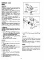
4.0 RESERVE POWER
22" POWER-PROPELLED
LA WN M 0 WER
THIS MOWER
TO DEPRESS
FOR FURTHER
COMPLIES WITH CPSC REGULATIONS
EFFECT|VE JUNE 30, 1982, TO START THE ENGLNE tT tS NECESSARY
THE CONTROL
BAR WHEN STANDING
BEHIND THE MOWER,
BEFORE PULLING ON THE STARTER
ROPE,
STARTING
SEARS,
_ART NO.
87867
REV.
DETAILS
SEE PAGE
ROEBUCK
2 4!5/88
8 OF THIS
AND
MANUAL,
CO.,
CHICAGO,
IL 60684
U.S.A.
CRAFTSMAN
quality LAWN CARE equipment
TWO
YEAR
LIMITED
WARRANTY
ONCRAftSMAN
POWER
MOWEn
For two years from the date of purchase, when this Craftsman power mower is maintained, lubricated and
tuned-up according to the instructions in the owner's manual, Sears will repair, free of charge, any defect
in material and workmanship.
If this Craftsman power mower is used for commercial or rental purposes, this warranty
90 days from the date of purchase.
This warranty
applies for only
does not cover:
Expendable items which become worn during
adapters, belts, air cleaners and spark plug.
normal
use, such as rotary
mower blades,
blade
Repairs necessary because of operator abuse or negligence, including bent crankshafts and the failure
to maintain the equipment acc0rdingt 9 the instructions contained in the owner's manual.
WARRANTY
SER ,C
AVA,
I
BLE
RETURN,NG
T.ECRAFTSM
POWER
N
MOWER
TO
T,E
NEAREST SERVICE CENTER/DEPARTMENT
This warranty
to state.
IN THE UNITED STATES.
gives you specific legal rights, and you may also have other rights which may vary from state
SEARS, ROEBUCK and CO. Department 698/731A
.... I'11r1'111111I[
MAINTENANCE
A SEARS MAINTENANCE
AGREEMENT
NEAREST SEARS STORE FOR DETAILS.
CUSTOMERS
Sears Tower, Chicago, III. 60684
Jl_
Ff,rrm_ffT
AGREEMENT
IS AVAILABLE
ON
THIS PRODUCT.
CONTACT
YOUR
RESPONSIBILITIES
Read and observe the rules for safe use. Always use care when using your lawn mower. Keep away from
moving parts.
DO NOT work on your lawn mower with engine running. Always keep your mower clean.
Follow a regular schedule in maintaining, caring for and using your lawn mower. A well cared for mower
will run and last longer.
Fallow the instructions under "Maintenance"
Blade, blade flange, ai_ _J_n_r/ai_
and "Storage"
sections of this Owner's Manual.
fiii_r, _park plug are expendable parts which are your responsibility.
TABLE
OF CONTENTS
WARRANTY
........................................................
KNOW YOUR CRAFTSMAN MOWER ........................................
RULES FOR SAFE USE ...................................................
HELP YOUR LAWN MOWER LAST LONGER ....................................
HOW TO SET-UP YOUR MOWER ...........................................
BEFORE STARTING ENGINE ...............................................
HOW TO USE YOUR MOWER .............................................
MAINTENANCE
.......................................................
STORAGE ...........................................................
REPAIR PARTS .......................................................
ENGINE REPAIR PARTS ................................................
TROUBLE SHOOTING
...................
................................
2
3
4
5
6
8
9
11
15
17
24
16
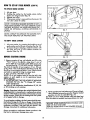
KNOW
YOUR CRAFTSMAN®MOWER
ZONE/ENGINE
CONTROL
HANDLE
KN(
CABLE CLIP
GRASS CATCHER
HANDLE
BRACKET
31NE OIL CAP WiTH
GASOLINE
ENGINE CONTROL
DIPSTICK
FILLER CAP
KNC
WHEEL ADJUSTER
(ON EACH WHEELI
PRIMER
AIR FILTER
DRIVE COVER
HOUSING
FIG. 1
MEETS
CPSC BLADE
SAFETY
SPECIFICATIONS
TOOLS
REQUIRED
FOR CATCHER ASSEMBLY
7/16" wrench or
adjustable wrench.
Medium phillips screwdriver.
FOR BLADE REMOVAL
Standard 15116" box or open
end wrench
Oil: Use SAE 30W motor oil. SAE 10W30
motor oil con also be used.
Gasoline:
Use unleaded
automotive
gasoffne. Regular automotive gasoline can
also be used. DO NOT use premium
gasoline.
_ears Rotary Walk-Behind
Sower Equipment lhstitute,
REQUIREMENTS
Power Mowers conform to the safety standards of the American
and U.S. Consumer Product Safety Commission, as applicable.
3
National
Standards
Institute, Outdoor
RULES
FOR SAFE
USE
CAUTION: ALWAYS DISCONNECT SPARK PLUG WiRE AND PLACE WIRE WHERE A
IT CANNOT CONTACT SPARK PLUG TO PREVENT ACCIDENTAL
STARTING
WHEN SETTING-UP, TRANSPORTING,
ADJUSTING OR MAKING REPAIRS TO
YOUR MOWER.
IMPORTANT
FEDERAL REGULATIONS REQUIRE THE ENGINE CONTROL INSTALLED ON THIS MOWER IN ORDER TO
MINIMIZE THE RISK OF BLADE CONTACT INJURY. DO NOT UNDER ANY CIRCUMSTANCE ATTEMPT TO
DEFEAT THE FUNCTION OF THE OPERATOR CONTROL.
1.
2.
I5.
Please read your owner's
manual.
Only allow persons who know the
safety rules to use your mower.
DO NOT tie the control bar to the han-
16.
dle. Control must be free to permit
brake engagement when handles and
control are released.
3.
4.
5.
6.
7.
8.
9.
17.
DO NOT altow children to use your
mower.
Check your mower over before each
time you mow. Tighten any loose
bolts, nuts, etc.
Remove all sticks, stones, wires, cans,
boards, etc. from area to be mowed.
These objects can be thrown by the
blade.
18.
19.
20.
21.
DO NOT allow children, bystanders,
or pets in the mowing area.
BE CAREFUL-WHEN
THE ENGINE
IS RUNNING
THE
BLADE
IS
TURNING.
22.
23.
Always shut off engine before trying
to adjust wheel heights.
When engine is running, DO NOT put
hands or feet under mower or in the
24.
discharge
chute,
nor make
any
adjustments.
10. Stay clear of discharge opening at all
times.
25.
11. Check gasoline before each use. Do
not fill gas tank when engine is running, when indoors or when engine is
hot. Allow engine to cool for several
minutes before filling gas tank. Clean
off any spilled gasoline before starting
engine.
26.
12. Mow onl_ in good light.
! 3. Wear on,y solid shoes when mowing.
DO
NOT
operate
mower
when
barefoot,
or wearing open sandals.
14. Disengage
drive control
on power
pro.pelled
engine.
mowers
before
27.
starting
4
DO NOT use a damaged mower.
Always
have damage
repaired
before mowing.
Always stop engine when not cutting
grass or when crossing gravel drive,
sidewalk, or roadway.
Never pull mower towards you,
always follow mower to cut grass.
Never use your mower without proper guards or deflectors in place.
Always mow across a slope or inclined area. DO NOT mow up or down
a slope or inclined area.
DO NOT mow in wet grass. DO NOT
run with the mower.
DO NOT run your mower indoors.
Exhaust gases are deadly poison.
DRAIN THE GASOLINE tank before
transporting your mower inside your
car or other vehicle.
DO NOT run your mower if it vibrates
too much. Stop engine and make
repairs. Vibration is an indication of
damage.
DO NOT change the engine governor settings to over-speed
the
engine--damage or injury can result.
If a grass catcher is used on your
mower, check the catcher often for
damage or deterioration.
Through
normal use it will wear. Use only
recommended replacement catcher.
Always
stop engine to remove
catcher.
DO NOT store your mower or
gasoline where fumes may reach an
open flame and cause a fire.
Always wear safety glasses or eye
shields before starting your lawn
mower and while mowing.
The operation of any lawn mower can result in foreign obiects thrown into the
eyes,, which can result in severe eye damage, Always wear safety glasses or eye
shields before starting your lawn mower and while mowing° We recommend Wide
Vision Safety Mask for over the spectacles or standard safety glasses, available
at Sears Retail or Catalog Stores,
ACCESSORIES
TO HELPYOU GETTHEMOST FROM YOUR MOWER
_OWER COVER: Sears Tyvek_cover, stock number 7) 33316, protects mower from weather when stored outdoors.
_vailable through Sears catalog.
_AS CAN: A new gas can keeps rust and dirt out of fuel system for longer engine life and improved performance. Craft_an gas cans have built in filters to keep impurities out of your engine and are available in Permanex ® polyethylene
,ith lifetime warranty and strong terneplate steel.
:LIPP1NG DEFLECTOR: Converts rear bagging mowers to side discharge to disperse safely and evenly, stock number
'1 33303 avai able in most retail stores, through catalog, Sears Central Service and parts desks.
N-TE
GH WHEEL K T A pair of 12-inch rear wheels improves handling on soft, spongy lawns and uneven terrain,
u
:
:the Z! 3372 t High Wheel Kit is purchased as an accessory, the cutting height range wilf be reduced to five (5) different
ositions; from 1 1/2" to 3 1/2". Available through catalog and Sears Central Service and Parts desks.
HESE ACCESSORIES WERE AVAILABLE AT MOST SEARS STORES AND THROUGH THE CATALOG AT THE TIME
HIS MANUAL WAS PRINTED.
IMPORTANTTIPS TO HELPYOUR LAWN MOWER STARTFASTER,RUN AND PERFORMBETTER
1.
USE UNLEADED GASOLINE:
It burns cleaner and leaves less residue in the engine. Regular gasoline can also be
2.
used. DO NOT use PREMIUM GASOLINE.
DRAIN OR RUN-OUT ALL GASOLINE FROM TANK AT THE END OF THE SEASON:
3.
in your mower when stored for long periods. It will "GUM"
your engine. Run engine until the gasoline runs out.
START EACH MOWING SEASON WITH FRESH GASOLINE: DO NOT keep gasoline in your can. If your gasoline
4.
can is starting to rust, replace can.
CHANGE YOUR SPARK PLUG EVERY SPRING: An old corroded
5.
running engine.
REPLACE YOUR AIR CLEANER OR FILTER OFTEN: Dirt, along with heat can harm your engine, the cleaner or
spark plug prevents fast starting and smooth
filter will clog up, preventing clean air from reaching your engine. See "Air
6,
for replacing air cleaner or filter_
USE SAE 30W OIL: DO NOT use SAE 10W40
7.
CHANGE
OIL AS RECOMMENDED:
DO NOT leave gasoline
Cleaner/Filter"
section of this manual
oil.
IMPORTANT
- change oil after the first two (2) hours of use, then every 25
hours of use.
8.
REPLACE THE BLADE WHEN
NEEDED: You can sharpen the blade,
but we do not recommend it. Erosion from
9.
hitting foreign objects can damage the blade, Replace blade with one specifically designed for your mower.
AT THE END OF THE SEASON, CLEAN YOUR MOWER: IMPORTANT - first disconnect the spark plug wire. If
possible, store your mower in a well ventilated area and protected from moisture.
O. FOLLOW THE MAINTENANCE
SUGGESTIONS IN YOUR OWNERS MANUAL: Read your manual and keep
it in a convenient piace_f-6i'_easy reference.
Your lawn mower has been completely assembled at the factory, except for the grass catcher. To set-up and attach gross
_tc_r,
follow the steps under "GRASS CATCHER"
The foflowing parts are included not assembled:
1
Grass Catcher Top Assembly
I
Grass Catcher Bottom
1
Hardware Package
UPRIGHT HANDLE
STORAGE POSITION
AND REMOVING
._,'- ",,
k _
l
t
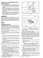
HOWTO SET-UPYOURMOWER
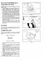
TO UNFOLDHANDLE
t.
Raise handles until the lower handle is in upright posh
tion (See Fig. 2).
NOTE: The lower handle automatically locks into the
upright storage position when raisedfrom
shipping
position.
2. Raise the upper handle into position on the lower handle and tighten the two (2) handle knobs.
3. The handle can be mounted in high or low position
to suit the comfort of the user. The handles are shipped mounted in the high position.
4. If the handle feels too high for you:
a. Remove the (2) screws, (2) bushings, (I) bolt and
Iocknut holding the trim plate and rope guide to lower
handle. Keep for re-assembly (See Fig. 4).
b. Remove the handle knobs and bolts from upper
and lower handle.
c. Remove the springs from mounting pins {bee Fig.
3).
d. Remove/ocknuts and bolts from handle brackets
and remove handle levers (Se Fig. 3).
e. Turn handle over, position handle levers in place
(See Fig. 4).
springs
backand/ocknuts
on mounting
pinsFig.
(See
. • Put
Reinstall
bolts
(See
3). Fig. 3).
. Put upper handle on lower handle using handle
bolts and knobs previously removed.
i. Put trim plate and rope guide back on lower handle, removed in (a) above. Tighten the (2) screws,
(2) bushiness,(t) bolt, tighten (2) screws and (I)
Iocknut (See Fig. 4).
I. Snap cable c;o over cable and lower handle [See
5.
6.
Fig.I).
Press the handle levers and the handle wilt
automatically lock in_o mowing position.
To fold handle for storage, press the handle levers
and move handle forward (Fig. 3).
CAUTION:
WHEN
FOLDING
HANDLE
FOR
TRANSPORTING OR STORAGE, BE SURE TO FOLD
HANDLE AS SHOWN
/N FIG. 5. /F YOU FOLD
HANDLE THE WRONG
WAY, YOU MAY BEND
THE CONTROL CABLES.
TO ADJUST
HEIGHTOF CUT
NOTE: The wheels are set in a low cut position for shipment, and should be adjusted for the cutting height desired
before use. NOTICE: Lowering wheels raises the height
of cut.
MOWING
POSITION
l
_,;
I
J
LOCKNUT
HANDLE
BRACKET
FIG. 3
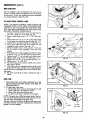
HOWTO SET-UPYOURMOWER(¢ONT'D)
LOW
TO ADJUSTHEIGHTOF CUT(CONT'D}
MED
CAUTION: DO NOT change the height of cut with the
engine running,
I. The wheel adiusters give you five (5) different cutting
positions. Medium cut is the best for most lawns.
2, High cut is approximately 3 3/8 "_, medium cut is ap• approximately
pro xIm" ately 2 5/8 _ t and low cut zs
1
I/8" There are two (2) other positlons. Pick the posi.
tion which suits you for best cutting (See Fig. 6).
3. The wheel adjusters on your lawn mower can be easi.
ly adjusted as shown in Fig. 7. To change the height
of cut, squeeze adjuster lever toward the wheel, moving up or down to selected height. Be sure all wheels
are in the same setting (See Fig. 6).
4. When cutting in heavy or moist grass, the rear of the
lawn mower may be raised one setting higher (by
lowering the wheels one setting) to allow better
discharge of the grass.
This will also make the unit push or propel easier
because it will reduce the drag of the rear of the
mower on the grass. This will not harm the cutting
performance.
t 11I
\
iIi
_
• WHEEL
j_s
ADJUSTER
SHOWN
WITH
LEVER
WHEEL
REMOVED
FIG. 6
REAR
DEFLEaOR
The rear deflector, attached between the rear wheels of
your lawn mower, was assembled at the factory and requires no assembly.
FIG,
7
T0 ASSEMBLE
GRASSCATCHER
NOTE: The grass catcher for your mower is supplied
unassembled. To assemble your grass catcher follow steps
below.
SCREW
CATCHER
1/4-20 x 3/4"
TRUSS HEAD
SCREW
TOP
\
ACTUAL SIZE
CATCHER
BOTTOM
1 4
1/4-20 x 3/4"" SCREW
START
HERE
FIG. 8
1.
Position top half of catcher on the bottom haft (See
Fig. 8).
2.
3.
4.
Insert I/4-20 x 3/4 truss head screw through right
front hole of catcher; install 1/4 nut on screw and
leave loose (See Fig. 8).
Insert a 1/4-20 x 3/4 screw through left front hole
of catcher; install !/4 nut on screw and leave loose.
Tighten screws installed in steps 2 & 3. Use a medium
phillips screwdriver to tighten the screws while
holding] the Iocknuts with adjustable
or 7/16"
wrench.
5. Install six more 1/4-20 x 3/4 screws, proceeding
around the catcher; leave Iocknuts loose.
6. Use a medium phl_fips s_ewdriver to tighten the remaining screws while holding the Iocknuts with adjustable or 7/16'" wrench.
NOTE: Check all screws and nuts to be sure they are tight.
20
KEPS NUTS
HOWTO SET-UPYOURMOWER(¢ONT'I))
JNGE BRACKET
TO ATTACFI
GRASSCATCHER
1.
2.
3.
4.
Lift rear door.
Holding the catcher by the handle, place catcher
frame onto hinge bracket (Fig. 9).
Release rear door.
When grass catcher is removed from the mower, the
rear door closes for safety.
NOTE: YOUR REAR BAGGER MOWER IS NOT A
MULCHING
MOWER. DO NOT OPERATE YOUR
MOWER WITHOUT AN APPROVED GRASS CA T.
CHER OR OPTIONAL CLIPPING DEFLECTOR IN
PLACE.
DOOR
OPEN
\\
FiG 9
NEVER ATTEMPT TO OPERATE THE MOWER WITH
THE DOOR REMOVED OR PROPPED OPEN.
TO EMPTYGRASSCATCH[R
1.
2.
Lift grass catcher, by grasping the handle on top of
grass catcher and on the rear of catcher (See Fig. 10).
To empty the grass clippings, shake the catcher, with
the open end aver or inta suitable container for
disposal (See Fig. t0).
BEFORE
STARTING
ENGINE
FIG. 10
i. Remove engine oil cap with dipstick and fill to the
"FULL" line on the dipstick, using about 1 pint of
Sears 30W all or equivalent. SAE 30W oil can also
be used(See Fig. 11). DO NOT use SAE lOW40 oil.
The total oil capacity of your engine is 21 oz. Fill only
to the "FULL'" line on the dipstick. DO NO T over fill. The
first fill on a new engine use about I pint. Check oil Jevel
and add as required to bring to proper level.
2. Pour oil slowly, DO NOT over fill.
NOTE: On a new engine some oil may be left in the
engine, as each engine is run for operational checks
before shipping.
3. AFTER THE FIRST TWO (2) HOURS OF MOWING
CHANGE THE OIL. See "To Change Oil" section
under maintenance.
Use only all with automotive classifications SF, SE, SD
or SC markings on oil container.
GASOLINE
FILLER CAP
OIL FILLERPLUG
FIG. 11
_c:ll_e g:Experience indicates that alcohol blended fuels
asohoi or using ethanol or methanol) can attract
moisture which leads to separation and formation of acids
duri'ng storage. Addi'c gas can damage the fuel system
of an engine while in storage.
4. Fill the gasoline tank with about one (I) quart of fresh,
clean unleaded automotive gasoline. Regular leaded
gasohne can also be used (See Fig. 11).
DO NOT use old or stale gasoline which has been kept
from one season to another; starting problems can result.
To ovoid engine problems, the fuel systemshould be emptied before storage for 30 days or longer. Dram the gas
tank, start the engine and let # run until the fuel lines and
carburetor are empty. Use fre.sh fuel next season. See
Storage Insh_uctions for additional information.
BE SURE YOUR GASOLINE CAN IS CLEAN AND J
FREE OF RUST AND DIRT.
REPLACE YOUR CAN IF IT HAS STARTED TO RUST.
Never use engine or carburetor cleaner products in the
fuel tank or permanent damage may occur.
$
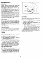
HOWTO USEYOURMOWER
iMPORTANT
ENGINE¢OHTROL
CAUTION: THE BLADE TURNS WHEN THE ENGINE
15 RUNNING.
YOUR MOWER tS EQUIPPED WITH AN OPERA TOR
ZONE ENGINE CONTROL WHICH REQUIRES THE
OPERATOR
TO BE POSITIONED
BEHIND
THE
MOWER HANDLE TO START AND OPERATE THE
MOWER.
THE CONTROL BAR MUST BE DEPRESSED TO THE
HANDLE TO 5TART AND RUN THE ENGINE, RELEASING THE CONTROL BAR WILL STOP THE ENGINE.
AN INTERNAL ENGINE BRAKE ASSISTS THE BLADE
IN STOPPING QUICKL Y.
WHEN
THE OPERATOR LEAVES THE NORMAL
MOWING POSITION TO REMOVE THE GRASS CATCHER, CHANGE THE CUTTING HEIGHT, PICK UP
5TICK5 OR OTHER OBJECT5 IN THE MOWING PATH,
THE ENGINE WILL AUTOMATICALLY
STOP WHEN
THE CONTROL BAR IS RELEASED.
FIG.
CONTROL
12
BAR
/
CAUTION;
FEDERAL REGULATIONS REQUIRE THE
ENGINE CONTROL INSTALLED ON THIS MOWER IN
ORDER TO MINIMIZE THE RISK OF BLADE CONTACT
INJUR Y. DO NOT UNDER ANY CIRCUM5TANCE A TTEMPT TO DEFEAT THE FUNCTION
OF THE
OPERATOR CONTROL.
;INE
CONTROL
CONTROL
OR_VE CONTRO
TO ENGAGE
DISENGAGED
DRIVE CONTROL.
FIG,
13
ENGINECONTROL
The engine speed is controlled by a lever (red knob)
located on right side of engine, It has '_HIGH'" and
"LOW"positions.
"'HIGH" position is for starting engine,
heavy cutting and better grass bagging. "LOW" position is for light cutting, trimming and fuel economy (See
Fig. 12).
TO STARTENGINE
THE CONTROL BAR MU5T BE DEPRE55ED TO THE
HANDLE TO 5TART AND RUN THE ENGINE.
CONTROL
CONTROL
RELEASED
ENGINE STOP
NOTE: The carburetor has a fixed fuel mixture and has
a primer to assist starting.
I. Check oil level; check gasoline tank for _]asoline; and
make sure spark plug wire is attachea,
2. Push lever forward to "HIGH"position
(See Fig. 12).
3. When starting a cold engine, push the primer five (5)
times before pulling starter rope. Use firm pushes
when pushing primer, wait several seconds between
each push (See Fig. 12).
4. Repeat step 3 above as required.
NO TE: In cooler weather the need to repeat priming procedures may be necessary, when weather is warmer over
priming may result in flooding.
If you do flood engine wait a few minutes before
repeating priming procedures.
It is not necessary to use t_rner
to start warm engine,
5. Position yourself as shown in Fig. 15.
6. Pull on starter handle quickly.
7. DO NOT allow starter rope to snap back.
8, To stop the engine, release the control bar (See Fig.
14).
g
START.
DEPRESSED
RUN
FIG.
14
FIG,
15
j
HOW TO USEYOURMOWER((ONT'D)
IF ENGINEDOESNOTSTART
1. Check blade - remove spark plug wire when checking
blade. If blade is loose, see "BLADE AND BLADE
FLANGE CARE" of manual for instructionson tightening blade.
2. Check air filter - replace ff dogged. ,See "Air Filter"
section.
3. Check spark plug . if dirty, clean or replace.
4. Observe that lower end of the engine control cable
is actuating the lever mounted on the engine.
5. Engine may be flooded - wait a few minutes and
repeat starting procedure.
NOTE: If then your engine will not start, contact your
nearest Sears Service Department for help.
FIG. 16
ZONE/ENGINE
CONTROL
Your mower is equipped with a zone/engine control attached and requires no adjustments (See Fig. 13).
DRIVE CONTROL
The power-propelling forward motion is controlled by
pulling the control bar down to handle and pushing the
drive control lever forward until it clicks, then release the
lever (See Fig. 13).
Forward motion wil! stop when the control bar isreleased.
To stop forward motion without stopping the engine,
release the control bar slightly untilthe drive control
disengages. Depress control bar to handle to continue
mowing without self-propelling.
To turn corners, you may prefer to keep the drive control
engaged, and push down on the handle, lifting the front
wheels off the ground and turning mower.
FIG. 17
BLOCK
OF WOOD
POWER-PROPELLED
DRIVE
1. Your power-propelled drive is accomplished by a belt
drive from the engine crankshaft to a Worm gear case.
2. The drive belt is sprlng.loaded at the gear case to
maintain proper belt tension. Keep the area around
the gear case clear of trash by removing drive cover
and deanlng (See Fig. 16 and 17).
3. The gear case is lubricated
with multi.purpose
automotive grease. DO NOT USE ANY OTHER type
grease or oil in the gear case. See "GEAR CASE'"
under "Maintenance".
4. Check your mower, each time you mow, to be sure
that the front wheels turn freely. If wheels DO NOT
turn freely, remove any trash which may have gotten
into the wheel, pinion, or bearing areas.
5. If at any time, the drive belt is replaced, use only factory specified belt to get longer life and maximum
performance.
FIG. 18
BLADE FLANGE
CRANKSHAFT
&
DETAIL
_
RANKSHAFT
SLOT
LADE NUT
MOWINGTIPS
BLADE WASHERS
I.
Under certain conditions it may be necessary to raise
the height of cut to keep from overloading the engine
and leaving dumps of grass clippings.
BLADE FLANGE
TAB
_ADE
FIG.
10
19
HOW
TO USE YOUR
MOWER
(CaNT'D)
MOWING
TIPS(C0NT'D)
2, For extremely heavy cutting, make the width of your
cut 1/2 to 3/4 the normo/ cut, This will reduce the load
on the engine and give you cleaner cutting and
bagging.
3. The user should note that when cutting moist, heavy
grass with a rear bagging mower, dumps of cut grass
may fail to enter the grass catcher. To pick up the
dumps if they occur, run the mower over the area a
second time.
4. Under certain conditions a trail of grass dippings may
be left at the right side of the mower. Mowing in a
clockwise direction with a small overlap will allow
these clippings to be collected on next pass.
FIG.
20
MAINTENANCE
APPROX
Be good to your mower. Once a year put in a new spark
plug, a new air filter and check blade for wear. A new
blade cuts better. With a new spark plug your engine will
start and run better. A clean air filter assures proper airfuel mixture, tt will help your engine run better and last
longer.
,'32 '_
HEX HEAD SCREW
MOWER:
BLADE/BLADE
FLANGECARE
CA UTION: Protect your hands when removing or installing blade of your mower, Wear heavy gloves
and/or wrap blade with heavy cloth when holding
blade. Always use a block of wood when tightening
blade nut or blade bolt.
FIG, 21
8. Tighten blade nut. The recommended tightening tor_
qbue is 70-75 ft. Ibs. Use block of wood to prevent
lade rotation.
NOTE: Torque wrenches are available at most Sears
retail stores and through the catalog.
A loose blade can result in difficult starting of engine.
We DO NOT recommend sharpening blade - you can
keep the cutting edge touched up with a file. Grinding the
cutting edge excessively can cause the blade to be out
of balance. An unbalanced blade can cause excessive
vibration and shorten the fife of the engine and mower.
Use only a Sears authorized replacement blade to get
the best cutting results,
CAUTION: Disconnect spark plug wire from spark plug
and place wire where it cannot come in contact with the
spark plug.
1. To remove the blade and blade flange, turn mower
on its side with carburetor and air filter up (See Fig.
18).
2.
Take blade nut off by turning counter-clockwise. Use
a 15/16" box or open end wrench on the blade nut
TO CHECKAND/TO REPLACEBELT
(SeeFig. 7e).
1. Remove the drive cover by removing the two (2)
screws (See Fig. 16).
2. Inspect belt for wear or damage. If you decide to
replace:
a. Push down on gear case pulley until belt can be
removed from gear case pulley (See Fig. 20).
3. Turn mower on its side with carburetor up,
4. Loosen hex head screw holding belt snubber in place
and move belt snubber away from pulley (See Fig.
3. Put a block of wood between the blade and mower
housing to prevent blade rotation when removing and
tightening blade nut.
NOTE: Always check the blade flange when changing
the blade to be sure tab has not been damaged (See Fig.
19).
4, if the tab in the blade flange is damaged replace the
blade flange.
NOTE: The blade flange with tab attaches the blade to
crankshaft. It is not intended to protect the crankshaft. The
tab must be in good condition and located in slot af
crankshaft to keep blade attached.
5. Put the blade flange on the engine crankshaft with the
tab in the slot of-the.cr_ankshaft (See Fig. 19).
6. Put the blade on the crankshaft as shown in (Fig. 19).
Be sure the word "TOP" (stamped in the blade) is
toward the engine,
7_ Install the flat washer, two (2) formed washers and
blade nut as removed above.
NOTE: We recommend that the blade nut be replaced
when installing a new blade.
21).
1!
5. Remove belt from engine pulley on crankshaft and
carefully slip the belt off over the blade.
CAUTION:
The sharp edges of blade can cut the belt.
Use care in installing new belt over blade.
6, To install new belt, reverse procedure as above in
removal.
7, Move belt snubber back in place, approximately
1/32" away from belt and tighten hex head screw
(See Fig_ 21).
NOTE: Always use only factory approved belt to assure
proper fit and longer life,
MAINTENANCE
(CONT°D)
REARDEFLECTOR
The rear deflector which is attached to the rear of your
mower is to keep objects from being thrown out the back
of the mower. If your rear deflector becomes damaged
you should-replace it (See Fig. 22).
TO ADJUSTDRIVE CONTROLCABLE
NOTE: THE DRIVE CONTROL CABLE SHOULD BE
CHECKED OFTEN TO BE SURE THAT GEAR CASE
SHIFTER tS FULLY ENGAGED OR WHENEVER SERVICE HAS BEEN PERFORMED ON THE GEAR CASE
OR DRIVE CONTROL COMPONENTS.
1. To adjust, remove the drive cover by removing two
(2) screws. Keep for re-use [See Fig. 16).
2. Loosen cable clamp screws "A" & "B" (See Figs.
23).
3, Loosen both jam nuts "C" & "D" at the cable clamp
on the gear case adjusting bracket (See Fig. 17).
4. Unhook clutchspring from shifter arm (See Fig. 17).
5. Hold, clip or tape down the drive control bar and
engage the drive control (See Fig. 13).
6. Move the shifter arm to drive position. To be sure
the jaw clutch is fully engaged, rotate the front
wheels.
7. Hold shifter arm in fully engaged position by pliers
as shown in Fig. 17. DO NOT pull on controt cable.
8. Tighten jam nut "'C'" up to bracket until cable is snug.
9, Tighten cable clamp screw "B" (See Figs. 17).
10. Tighten jam nut "'D'" up to bracket (See Fig. 17).
t 1, Tighten screw "A'" (Fig. 23).
12, Put clutch spring back in place on shifter arm, removed in step 4 above.
t3, With drive control in engaged position, push mower
back and forth to be sure gear case isfully engaged.
NOTE: Be sure to disengage drive control before starting engine.
t4. Put drive cover back in place, removed in step I
above.
REAR DEFLECTOR
FIG. 22
I
\
FIG. 23
GEARCASE
I. THE GEAR CASE AND AREA AROUND ALL THE
DRIVE SHOULD BE KEPT CLEAN AND FREE OF
TRASH BUILD-UP.
2. To check gear case area:
a, Remove the drive cover by removing the two (2)
screws (See Fig. 16). Keep for re-use.
b. Clean trash from around gear case.
c. Put drive cover back, removed in (a) above.
FIG. 24
COTTER
i
NOTE: The gear case is filled to proper level at the factory. The only time the lubricant needs attention is ff service has been performed on the gear case.
The gear case mustbe filled with grease after gear case
has been serviced. Use only multi-purpose automotive
grease. Do not substitute.
WASHER
HUBCAP
FIG. 25
12
MAINTENANCE{CONT'D)
LUBRICATION
MOWER WHEELS: Lubricating wheels and/or wheel
bearings is not necessary under normal conditions.
Should conditions require lubricaiton, thoroughly clean
wheels and/or wheel bearings and axles and apply a light
coating of dry lubricant.
REAR DOOR HINGE: Put a few drops of the same all
as used in the engine on hinge points of rear door once
or twice each year (See Fig. 24).
GEAR CASE: The gear case is filled at the factory and
does not require any addition of lubricant, unless the gear
case is opened and service performed. Use only a multipurpose automotive grease for refilling after service has
been performed. Approximately
2 I/2 oz. required.
FRONT WHEEL ADJUSTER5: Put a few drops of the
same oil as used in the engine on the front whee! adjusters
once or twice each year (See Fig. 25).
CONTROL
LEVER
FIG. 26
DRIVE WHEELS
NOTE: Check front drive wheels each time before you
mow, to be sure they move freely.
1. The wheels not turning freely, indicates trash, grass,
cuttings, etc. are in the drive wheel area, and must
be cleaned to free drive wheels.
2. If necessary to clean the drive wheels (See Fig. 25)
check both front wheels.
a. Remove hub caps, hairpin cotters and washers.
Keep for re-use.
b. Remove wheel from wheel adjusters.
c. Remove any trash, grass cuttings from inside the
dust cover, pinion and/or drive wheel gear teeth.
d. Put wheels back in reverse of removal.
3. If after cleaning drive wheel area, the drive wheels
DO NOT rotate freely, the gear case needs care.
NOTE: If your gear case requires service we suggest that
you contact Sears Service Center.
GRASSCATCHER
Check your grass catcher often for damage or deterioration. Through normal use it will wear. If catcher needs
replacing, replace only with a manufacturer approved
replacement catcher from Sears. Give the mower number
when ordering.
NOTE: The catcher may be hosed with water, but must
be dry when used.
ZONE/CONTROLLEVER
Put one or two drops of the same oil as used in the engine
between the zone control lever and bracket located on
left rear of engine [See Fig. 26). Do this once or twice
each year.
CLEANING
CAUTION: Disconnect spark plug wire from spark plug
and place wire where it cannot come in contact with the
spark plug.
I. Turn mower on its side with carburetor up.
2. Clean the underside of your mower by scraping to
remove build-up of grass and trash.
NOTE: We recommend that you clean the underside of
your mower after each use.
3. Clean your mower and engine often to keep build-up
of trash from accumulating around engine; a clogged engine runs hotter and shortens engine life.
NOTE: We DO NOT recommend using a garden hose
to.dean mower unless the electrical system, muffler, air
filter and carburetor are covered to keep water out.
Water in engine can result in shortening engine life.
GEARCASEAND DRIVE WHEELS
NOTE: The gear case and drive wheels should be cared
for much like you would on automobile.
I. On a regular schedule remove the drive cover and
remove any trash around gear case and belt area.
2. To remove drive cover,_rems2yethe two (2) screws (See
Fig. 16). Keep for re-use.
3. Keep your mower clean and properly lubricated.
_3
IIITWANC|
(¢ONT'D)
M61NE:
LUflR TION
!
ENGINE: use of proper oi1 in your engine and keeping
to full level is essential. Changing oil regularly will
lengthen the llfe of your engine.
The total oil capacity of your engine is 21 oz. Fill onty
to the "FUtL " line on the dipstick. DO NOT overfill. The
first fill on a new engine use about l pint. Check oil level
and odd as required to bring to proper level.
NOTE: On a new engine some oil may be left in the
engine, as each engine is run for operational checks
before shipping.
Use Sears SAE 30Wail or equivalent. SAE lOW30 oil
can also be used. DO NOT use SAE lOW40 oil.
Use only oil with automotive classifications SF, SE, SD
or SC markings on oil container.
Using Sears SAE lOW30 oi! witt assist engine starting
in coot weather,
Running your engine with oil below safe/evet or with dirty
contaminated oil can contribute to shortening the fife of
yAour engine.
tier the first two (2) hours of mowing change the oil, then
change the oil every 25 hours of mowing thereafter, ff
you mow under dusty, dirty conditions you may need to
change the oil more often.
FIG. 27
COLLAR
/
SLOT
TAB
AIR FILTER COVER
FIG. 28
CAUTION: Disconnect spark ptug wire from spark plug
and place wire where it cannot come in contact withthe
spark plug.
I. Remove engine oil cap with dipstick, lay aside on a
clean surface. Warm oil drains better.
2. Tip mower on its side as shown in Fig. 27 and drain
oil into suitable container. Rock mower back and forth
4.
5,
TURN CLOCKWISE
TIGHTEN
AIR FILTER
TO CHANGE01L
3.
cONTAiNER
5. Put air filter cover and filter into co//or aligning the
tab with the s/at.
6. Pushin on cover and turn clockwise to tighten (See Fig.
28).
to remove any oil trapped inside of engine.
Wipe off any spilled on!on mower and/or inside of
engine.
Fill engine with oil, fill only to the "FULL"line
on the
dipstick. DO NOT over fill,
Reconnect spark plug wire to spark plug.
SPARKPLUG
Change your spark plug each year.
A new clean spark plug will make your engine start and
run better. Keep your spark plug clean. Set spark plug
gRaPat .030.
ecommended replacement Sears spark plug no.
7_1r333I2 or 3TD361458 are available at most Sears
retail stores and through the catalog.
AIR FILTER
CAUTION: DO NOT run your engine without air filter
in place.
i . Your engine will not runproperly with a clogged, dirty
air filter.
NOTE: DO NOT wash this type air filter.
2. Replace your air filter each year, more ohen ff you
mow in very dusty, dirty conditions.
Replacement air filter no. _3332
is available at most
Sears retail stores and through the catalog.
GENERAL
DO NOT usegasoline left over from previous season. Old
or stale dirty gasoline can cause starting and running
problems.
Replace your gasoline can, if your old can starts to rust.
DO NOT use rusty gasoline can, rust and/or dirt in your
gasoline can cause problems.
TO CHANGE
AIR FILTER
I. Remove the air fitter cover by turning counterclockwise to the stop, and pull away from col/or (See
Fig. 28).
2, Remove filter from inside of cover (See Fig, 28).
3. Cleon the inside of the cover and the collar to remove
any dirt accumulation.
4. Insert new filter into cover.
"t4
STOOGE
Never store engine with gasoline in tank, indoors or in
closed, poorly ventilated areas where gasoline fumesmay
reach an open flame, spark or pilot light as on a furnace,
water heater, or clothes dryer, etc.
It is important to prevent gum deposits from forming in
essential fuel system parts such as the carburetor, fuel
filter, fuel hose, or tank during storage. Also, experience
indicates that alcohol blended fuels (called gasohol or using ethanol or methanol] can attract moisture which leads
to separation and formation of acids during storage.
Acidic gas can damage the fuel system of an engine while
in storage.
To avoid engine problems, the fuel system should be emptied before storage of 30 days or longer. Follow these
instructions:
if your engine is not to be used for 30 days or more
prepare as follows:
Drain gasoline From fuel tank; gasoline in gasoline tank
and carburetor will farm deposits and cause problems in
starting and running your engine.
When preparing your mowerfor storage it is a good time
to serviceyour mower and engine to be ready for the next
mowing season. Replace such parts as mower blade,
spark plug and air filter,
CHANGE OIL: Warm oil drains better,
Drain old oil and replace with fresh clean Sears SAE 30W
oil.
See "To Change Oil" section under Maintenance.
Remove spark plug and put 2 or 3 tablespoons atoll into
s_isark plug opening and pull starter rope slowly to
tribute oil, instaJlnew spark plug and tighten.
DO NOT PUT ANY ADDITIVES IN GASOLINE OR OIL.
CLEANMOWE_ENblNE
CAUTION: Before cleaning mower, disconnect spark
plug wire and place wire where it cannot come in contact
with the spark plug.
Clean around engine and on top of mower. Scrape underside of mower using putty knife or similar toot to remove
any build.up of trash or grass on underside of mower
housing.
NOTE: We DO NOT recommend using a water hose to
clean your mower unlessthe electrical system, muffler, air
filter and carburetor are covered to keep water out.
Water in engine can result in shortening engine life.
CHECKFASTENERS
Check all fasteners and be sure they ore tight: tighten
and/or replace any loose or worn fasteners.
GRASSTCHER
Check your grass catcher often for damage or deterioration. Through normal use it will wear. If catcher needs
replacing, replace only with a manufacturer approved
replacement catcher from Sears. Give the mower model
when ordering.
NOTE: The catcher may be hosed with water, but must
be dry when used.
FIG. 29
REPLACE
BLADE
See "Blade Care" section under Maintenance. To get the
bestcutting results we recommend that you inspect mower
blade for sharpness, wear and damage each year. If
necessary, replace with a Sears original equipment blade.
Replacement blade is available at most Sears stares and
through the catalog. Be sure to give your mower model
number when ordering blade.
We DO NOT recommend sharpening blade - you can
keep the cutting edge touched up with a file. Grinding the
cutting edge excessively can cause the blade to be out
of balance. An unbalanced blade can cause excessive
vibration and shorten the life of the engine and mower.
GENERAL
Always store your mower on its wheels. 5taring mower
on its side or end may result in difficult starting.
When removing your mower from storage, fill gasoline
tank with fresh, clean, unleaded, automotive gasoline.
Check and fill oil to proper level.
When starting your engine the first time after being in
storage for extended period, the engine may smoke for
a while until the engine burns any oi! or gasoline accumulated during the storage period.
DO NOT store gasoline from one season to another. Use
up or dispose of any unused gasoline left from the mowing season.
Replace your gasoline con if your can starts to rust. DO
NOT use rusty gasoline can. Rust and/or dirt in your
gasoline can cause problems.
DO NOT store your mower under any plastic coverj
plastic cannot breathe which promotes condensation and
can cause your mower to rust.
HANDLE
You can fold your mower handle far storage (See Fig.
29).
When setting.up your handle from storage position the
lower handle will automatically lock into mowing position.
[ TROUBLE
SHOOTING
POINTSt
CORRECTION
CAUSE
PROBLEM
.
Out of gasoline.
2. "Stale Gasoline."
3. Spark plug wire is disconnected from the spark plug.
4 Bad spark plu_.
5 Water in gasoline.
6
Loose blade or broken blade
flange.
7 Zone/Engine control in
released position.
8. ZonelEngine control does not
function.
.
,
3
4
Poor cut-
Rear of mower housing/blade
dragging in heavy grass.
Cutting too much grass.
Dirty air filter
Build-up of grass, leaves,
and trash.
1_ Fill gasoline tank.
2. Drain gas tank and refill with
gasoline.
3. Connect wire to spark plug.
.• Drain
Replacetank
spark
andplug.
refill with fresh, clean
gasoline.
6. Tighten blade bolt and/or replace blade
flange.
7. Depress control bar
8. Replace ZonelEngine
control.
1. Raise rear of mower housing
one _(1) setting.
2. Set in "Higher Cut" position.
3. Clean or replace air filter
4. Disconnect spark plug wire and
clean underside of mower housing.
Uneven
1 Worn or bent blade.
2 Wheel heights uneven.
1. Replace blade.
2. Set all wheels at same height.
Toomuch
Vibration
t . Worn or bent blades.
2. Loose bJade.
1. Replace blades.
2. Tighten blade nut.
Starter Rape
Hard to Puff
1 . Flywhee_ brake is on when
control bar is released.
2. Bent crankshaft.
3. Btade flange sheared.
I . Depress control bar, before pulling
on starter rope.
2. Replace crankshaft.
3. Replace blade flange.
Catcher Not
Fillina
Completely
1 . Cutting height too tow.
2. Lift on blade worn off.
3. Catcher bag dirty, poor
air venting.
1_ Raise _:utting height.
2. Replace blade•
3 Clean/replace catcher bag.
(If optional grass catcher
is being used).
1G
fresh
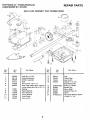
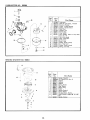
CRAFTSMAN
22" POWER-PROPELLED
LAWN MOWER 917.372260
GEAR
CASE
REPAIR PARTS
ASSEMBLY
PART
NUMBER
88387
15
14
\
i
i
23
Ref,
No.
Part
No.
,,,,
, ,
,
1
2
3
4
5
6
53838
85178
88386
57072
57388
48032
7
8
9
10
11
12
77881
77039
79946
57079
75144
87822
,,
Part Name
Ref.
No.
Part
No.
Part Name
-
Keps Nut 1/4-20
Adjusting Bracket
Shifter Assembly
Seat
Driv-Lok Pin t/8 x t/2
13
t4
15
16
86447
83659
75424
58354
Gear Case Halves (Incl. Upper &
Lower Halves) (Incl. Ref. # 4, 5, 7)
Bearing
Spring Bracket
Drive Shaft Kit
Thrust Washer
Yoke Clutch
Driv-Lok Pin
17
t8
19
20
21
22
STD581050
83684
83720
65692
83680
STD522512
17
Plug
Helical Gear
Jaw Clutch
Grease (1 Ib, can Shell Darina AX)
E-Ring 1/2 Shaft
Square Key
Worm Shaft
Woodruff Key #3
Worm
Hex Head Machine Screw
1/4-20x
t t/4
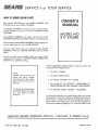
CRAFTSMAN
22" POWER-PROPELLED
LAWNMOWER
917.372260
REPAIR PARTS
5O
53
51
27
24
47
42
oo
_2
33
5O
\
47
56
53
CRA STMAN
22""POWER-PROPELLED
LAWNMOWER
917.3;,226o
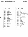
Ref.
No.
Part
No.
1
2
3
4
5
6
7
8
9
10
11
12
13
84086
87879
86874
78186
87722
8381363688
58714
87716
85424
85529
85825
85436
14
15
63601
34372A
16
17
18
19
20
87670
87672
STD581031
59289
87880
Part Name
Upper Handle
Lower Handle
Zone Engine Control
Zone Control
Cable Assembly
He× Head Screw 10-32 x 3/8
Handle Knob
Handle Bolt
Control Cable Clip
Trim Plate
Nylon Bushing
Self-Tapping Screw 10-24 x 1
Hex Washer Head Machine Screw
1/4-20x
1 1/2
Locknut 1/4-20
Bracket Rope Guide (See Engine
Parts List) (Source 143)
Handle Lever - L.H.
Handle Lever - R.H.
E-Ring
Washer
Shoulder Bolt
REPAIR PARTS
Ref.
No.
Part
No.
Part Name
21
22
23
24
25
26
27
28
87881
87152
87760
87626
87569
87145
STD581025
STD5t2505
29
81283
Hex Self Tapping
3/8
30
31
32
33
34
STD511005
87656
87595
87747
86779
Truss Head
Back Plate
Side Baffle
35
36
37
38
69180
87862
87864
55187
Locknut
Shoulder
Nut
Spring
Rear Door
Hinge
Bracket
Hinge Rod
Spring
_ _Lf3_b
L_ _ it _
(_ _3_-3_
_
E-Ring
Hex Head Tapping
1/4-20
x 1/2
Screw
Screw
Screw
Discharge
Bafle
Hex Head Machine
1/4-20
x 3/4
10-24
10-24
x
x 1/2
Screw
10-24
Handle
Handle
Bracket
Bracket
Thread
3/4
Cutting
- Right
- Left
Screw
5/16-18
x
b
L_'4_O,_
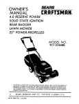
CRAFTSMAN
Ref,
No,
22"
POWER-PROPELLED
Part
No,
REAR-BAGGER
LAWN
MOWER
!
Part Name
REPAIR PARTS (C0NT'D)
917.372260
| Ref.
No.
i
Part
No.
Part Name
u= ill H Hnul,i
O
39
40
41
42
43
44
45
46
47
48
49
5O
51
52
53
54
55
56
57
58
59
6O
63124
STD533107
69478
85022
85463
84888
87877
84920
62335
84921
74400
87727
52160
55015
77400
70385
81276
51433
54867
69385
69334
87712
Locknut
5/16-18
6 1
68205
5/16-18
Carriage Bolt 5/16-18
x 5/8
Wheel Adjusting
Bracket
Axle Arm Assembly
Danger Decal
Selector
Spring
Selector
Knob
62
63
83629
48108
64
65
66
67
85543
87677
84089
85768
Wheel & Tire Assembly
Washer
68
69
Retainer Clip
Hub Cap
Cable Ciip
Self-Tapping
Screw 10-24
Locknut
5/8-18
(Special)
Washer - Spring
Washer
70
7!
72
73
STD502502
87029
87272
88366
88368
87641
Spacer Bearing
Spring Washer
Shoulder
Bolt
Locknut
3/8-16
Blade
Blade
Flange
Hex Head Machine
x 1/2
87867
48e6w4_#5
33721
33413
Screw
x 7/8
(Special)
Belt Snubber
Mower
Housing
Assembly
Ref # 28, 29, 30, 31, 32,
Engine Pulley
Hi-Pro Key #HP-505
Control Bail
(Incl.
63)
Hex Thread Roiling Screw
10-24 x 3/4
Set Screw 1/4-20
x 5/!6
Engine Decal
Instruction
Decal
Rear Skirt
Backing Strip
Engine Assembly
143.384092
(See Page 24 thru 26)
Owners Manual - Parts List
Grass Catcher Complete
High Wheel Kit (Not Included)
Leaf Catcher
,,,, ,, .,.i,
,, i
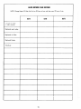
LAWN MOWER CARERECORD
NOTE: Change Engine Oil after the first two (2) hours of use, and then every 25 hours of use.
DATE
DATE
Change Oi! 30W
or SAE t0W30
Replaced
spark plug:
Replaced
air filter:
Replaced
blade:
Tuned-up:
I
91
DATE
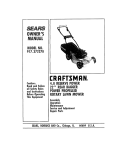
REPAIR PARTS
CRAFTSMAN
22"
POWER-PROPELLED
REAR-BAGGER
LAWN
MOWER
917.372260
6
i
4O
3
14
h_
h_
\
15
35
2O
_jt2
\
_38
\
17
2113
22
\
8
9
14 10
J
LEFT
FRONT
CRAFTSMAN
Ref.
No.
0
22"
POWER-PROPELLED
Part
No.
1
2
3
4
5
6
7
8
9
10
11
12
t3
14
15
t6
t7
18
87732
48029
48030
78186
74189
87729
52160
55015
77400
77862
77861
87877
86273
86274
88285
STD582087
86280
61528
19
20
21
22
23
24
25
26
27
28
29
63601
76401
74507
STD581050
STD601003
83700
48031
83681
STD582043
83691
54338
REAR-BAGGER
LAWN
Part Name
8.00
x 2
Retainer Clip
Hub Cap
Selector Spring (R.F.)
Selector
Selector
Spring (LF,)
Knob
REPAIR PARTS
917.372260
Ref.
No.
Drive Control
(Incl. Ref #2,3)
Drive Head Kit
Drive Control Cable Kit
Machine Screw 10-24 x 2
Locknut 10-24
Wheel & Tire Assembly
Washer
MOWER
Part
No,
30
3t
32
33
34
35
36
83632
68038
75192
STD580009
STD580014
87691
81276
37
87866
38
48095
Wheet Adjuster
Assembly
(Left)
(Incl. Ref # 11, t3, 14, 15, 16,
17)
39
48096
40
41
42
43
44
45
87871
69180
87679
87682
103227X
86988
Wheel Adjuster Assembly
(Right)
(Incl. Ref # 10, 13, 14, 15, 161
17)
Catcher Frame
Locknut
10-24
Catcher Bottom
Baffle
Handle
46
47
48
49
50
51
87873
87678
53838
87588
87870
33303
Spacer
Spring Washer
Axle Arm Assembly
Retaining Ring
Wheel Adjusting
Bracket
Flat Head Machine Screw
1/4-20 x 3/4
Locknut 1/4-20
Dust Cover
Pinion
E-Ring
Self-Tapping
Screw 10-24 x 3/8
Cable Clamp
Gear Case Replacement
Kit
Drive Pulley
Retaining
V-Belt
Ring
Hex Head Bolt 1/4-20
x 2 3/4
Part Name
Spring
Locknut
1/4-20
Spring
Woodruff
Key #213
Woodruff
Key #3
Drive Cover
Hex Head Tapping
10-24 x 1/2
Pan Head Machine
10-24x
2 3/4
Screw
#t0
x 1/2
Screw
Truss
Head
Machine
1/4-20
x 3/4
Truss Head Screw 10-24
Screw
x 318
Catcher Top
Locknut
1/4-20
Baffle Front
Truss
Head
Screw
Chute
Deflector
W/Mower)
1/4-20
(Not
x 5t8
Included
_126
38
82
87
Revised 10-22-87
81
24
37
17
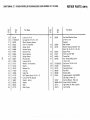
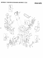
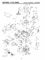
CRAFTSMAN
4"CYCLE
EHGINE
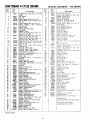
Ref.
Part
NO.
No.
I
35370
3
4
5
5
26727
32600
29314tB
29315C
6
6
29313C
29315C
9
10
11
12
t4
31672
31673
35175
32323
34851
14
34852
14
348.53
14A
14A
32603B
32604B
14A
32605B
15
15
15
16
17
18
21
22
34854
34855
34856
20381
30963B
326t0A
27241
38553
23
24
25
29914
*35261
34311B
26
27
28
30
31
32
33
34
35
35
37
38
39
_0
€1
¢2
$6
$7
_9
51
27897
*28833
30572
65O488
30590A
30574
30591
29193
30568A
31385
30589
28277
31383A
31361
650548
611004
*33015
34342
6O21A
35395
_2
S3
54
*27234
32755
30200
55
56
57
58
58A
59
60
62
34215
"32760
650128
34985
35168
MODEL
NUMSE.: 143.3840S2
Ref.
Part Name
No.
Cylinder Assy., (Incl. Nos. 3, 4, 54, 55
8 56)
Pin, Dowel
Seal, Oil
Valve, Intake (Std.} (Incl. No. 10)
Valve, Intake
(1/32"'
oversize)
(incl.
NO. 10)
Valve, Exhaust (Std.) (incl. No. 10)
Valve,
Exhaust
(t/32"
oversize)
(Incl. No. 10)
Spring, Valve
Cap, Lower valve spring
Crankshaft
Washer, Thrust
Piston, Pin 8 Ring Assy, (Std.) (Incl.
Nos, t4A, 15 8, 16)
Piston, Pin 8" Ring Asay, (.010 oversize) (Incl. Nos. 14A, 15 8, 16)
Piston, Pin 8" Ring Assy. (.020 oversize) (IncL Nos, 14A, 15 8" 16)
Piston 8, Pin Assy. (Std.} (incL No. 16)
Piston
8, Pin Assy.
(.010 oversize)
(Incl. No. 16)
Piston
8, Pin Assy.
(,020 oversize)
(Incl. No. 16)
Ring Set, Piston (Std.)
Ring Set, Piston (.010 oversize)
Ring Set, Piston (.020 oversize)
Ring, Piston pin retaining
Rod Assy., Connecting
(Incl. No. 18t
Screw, Connecting rod
Lifter, Valve
Camshaft
(Mech.
Compression
Release)
Pump Assy., Oil
Gasket, Mounting flange
Flange Assy., Mounting Ilncl. Nos. 26,
Revised
31384A
L
65O451
10-22=87
Seal, Oil
Gasket, Oil drain plug
Plug, Oil drain
Screw, Hex hd. Seres, 1/4-20 x %1/4
Washer, Flat
Shaft, Mechanical
governor
Gear Assy., Governor
(Incl. No. 31)
Ring, Retaining
Spool, Governor
Clamp, Governor
lever
Rod, Governor (Incl. No. 38)
Washer, Flat
Lever, Governor
Spring, Governor
Screw, Hex washer hd., 8-32 x 5/16
Key, Flywheel (Solid State}
Gasket, Cylinder head
Head, Cylinder
Screw, Hex flange hd., 5/16-18 x 1-1/2
Resistor Spark Plug (Champion
RJ!9LM or equivalent)
Gasket, Valve spring cover
Cover, Valve spring box
Screw,
Hex washer hd. Sems, selftapping,
10-24 x 9/!6
Breather Assy. (Incl. Nos. 54 8 56)
Gasket, Breather
Screw, Fil. hd. Seres, 10-24 x 1/2
Retainer, Starter rope
Bracket, Rope guide
-Gasket, Intake
Pipe,_ltrtake (Incl. No. 591
Screw, Hex hd. Seres, 1/4-20 x I
70
71
34337
30200
72
73
74
75
76
338O2
31342
650777
650549
33205A
77
78
79
32410
34336
35167
34961
35065
35067
*26756
6201
29752
35066
35068
333!
80
81
82
83
85
86
89
98
27,28,32)
Part
No.
99
35478
650831
100
30200
101
t02
102A
t03
105
106
107
108
120
12t
123
35586
35355
35480
26460
34357
650815
650816
35000
27181B
650795
650562
124
t25
!26
126A
130
!31
!33
134
!35
t36
!37
138
139
140
141
142
143
145
34265
35577
35578
35499
35392
650884
610118
34443A
650814
34080
611046A
35015A
34965
34966
32309
34968
610973
650839
150
15t
!52
632388
590621
33238C
Part Name
Link, Governor
spring
Screw,
Hex washer
hd. Sems, serftapping,
10-24 x 9/t6
Spring, Compression
Spring, Compression
Screw, Fil. hd, 6-32 x 21/32
Screw, Fil, hd., 5-40 x 7/t6
Control Assy., Speed Ilncl.
Nos, 72,
73, 74 8, 75)
Knob, Speed control
Link, Governor-to-throttle
Decal, Speed control
Wire, Ground
Cover, Air cleaner
Collar, Air cleaner
Gasket, Carburetor
Screw, Hex hd,, 1/4-28 x 78
Nut £f Lockwasher,
1 4-28
Filter, Air cleaner
Clamp, Air cleaner
Air C4eaner Kit _tncI. Nos. 8t, 82, 87 8"
88)
Housing,
Blower
Screw,
He× washer
hd.
Powedok
thread, 1/4-20 x 15 '32
Screw,
Hex washer
hd. Seres, selftapping,
10-24 x 9 16
Tank Assy,, Fuel flncf, No. 102 8 103t
Cap Fuel tank
Retainer,
Fuel cap
Clamp, Fuel line
Line, Fuel
Washer,
Belteville
Nut, Flywheel
Hub, StaRer
Muffler Assy. flncl, No, 121)
Screw, Hex hd,, 1 4-20 x 2-1 4
Screw,
Hex washer hd, shake-proof,
10-32 x 1 2
Gasket, Oil fill tube
Tube Assy., Oil fil!er
Dipstick,
Oil
"0" Ring
Plug, Starter
Screw, Hex washer hd., 8-32 x 1 2
Cover, Spark plug
Sotid State Assy.
Screw, Hex hd. Seres, 10-24 x 1
Spacer, Flywheel Key
Flywheel
Bracket Assy., Brake
Spring, Extension
Link, Control
Ring, Retaining
Lever, Brake
Terminal Assy,
Screw, Hex hd. serf tap Seres, 1 4-20
x 7q6
Carburetor
(IncL No. 83)
Starter, Rewind
Gasket Set flncI, items marked *)
RPM Settings:
Low Speed, 2050;
High
Speed,
*Indicates
Parts Included
in
Gasket Set, Ref, No. 152.
!
3000.
CARBURETOR
NO.
632388
"er;'"l'"'
P, t
No. [
N-.
Part
3
631616
4 [ 650506
15
5
6
7
I 631767
/ 631971
/ 631184
9 / 632047
!!
I 631027
12
I 631021
13 / 631022
15
16
2t
22
!4
25
I
}
/
I
I/
631024
631700
631334
631935
632019
631028
26_631775
REWIND
STARTER
Name
Carburetor
I 632388
Shaft _ Lever Assy,, Throttle
Shutter, Throttle
Screw, Throttle shutter
Spring, Throttle return
Seal, Dust
Washer, Flat
Primer Assy.
Plug, Welch
Inlet Needle,
Seat
8- Clip Assy.
(Incl. No. 13)
Clip, Inlet needle
Float, Carburetor
Shaft, Float
Bowl, Float
Gasket, Bowl-to-body
Nut, Float bowl
Gasket, Bowl4o-body
Fitting, Fuel inlet
NO. 590621
m
._:
'.... 11
Ref.
No.
12 ..........
!
\
8
10
¸
3
26
Part
No.
Part
Name
1
2
3
4
5
6
7
8
9
10
11
t2
590621
Starter, Rewind
590599A Pin, Spring (Incl, No, 4)
590600
Washer
590615 Retainer
590601 Washer
590598 Spring,
Brake
5,90616 Dog,
Starter
590617 Spring,
Dog
59O618 Pulley
590619 Spring,
Rewind
590620 Cover,
Spring
590622
Housing Assy., Starter
5905_35 Rope, Starter (Length 98" 8 9/64"
13
59O452
dia, )
Handle,
Starter
LAWNMOWERCARERECORD
NOTE: Change Engine Oil after the first two (2) hours of use, and then every 25 hours of use.
DATE
Change
or SAE
DATE
DATE
Oit 30W
10W30
Replaced spark plug:
,,
Replaced air filter:
Replaced blade:
Tuned-up:
ill.
i
u.,.
,.,,.,i.,i,,,.,
,,,
27
, , ',H',
SERVtCE is at YOUR
SERVICE
HOW TO ORDERREPAIBPARTS
Each LAWN MOWER has its own MODEL NUMBER.
ENGINE has its own MODEL NUMBER.
OWNER'S
MANUAL
Each
The MODEL NUMBER for the lawn mower will be found on
a plate attached to your lawn mower at the REAR OF THE
HOUSING.
MODEL NO.
917.372260
The MODEL NUMBER for the engine will be found on the
BLOWER HOUSING of the engine adiacent to the spark plug.
Always mention these MODEL NUMBERS when requesting service or repair parts for your LAWN MOWER.
All parts listed herein may be ordered through SEARS,
ROEBUCK AND CO. SERVICE CENTERS and most Retail
Stores.
If parts you need are not stocked locally your order will be
electronically transmitted to a SEARS PARTS DISTRIBUTION
CENTER for expedited handling.
WHEN ORDERING REPAIR PARTS, ALWAYS
FOLLOWING
INFORMATION:
Seria]
Number
Model and
GIVE THE
1. The PART NUMBER
Serial
Number
2. The PART DESCRIPTION
may be found on the number
plate on the rear of the mower
housing.
3. The MODEL NUMBER - 917.372260
You should record both Model
5, The ENGINE
and Serial Number and keep
in a safe place for future
reference.
4. The NAME OF THE PRODUCT - CRAFTSMAN 22"
POWER_PROPELLED REAR BAGGER LAWN MOWER
MODEL NUMBER - 14,3.384092
Your Sears merchandise has added value when you consider
that Sears has service units nationwide staffed with Sears trained technicians...professional technicians specifically trained on
Sears products, having the parts, tools and the equipment to
insure that we meet our pledge to you, we service what we sell.
SOLD BY SEARS,
PART NO. 87867
REV. 2 4/5/88
ROEBUCK
AND CO.,
CHICAGO,
IL 60684
U.S.A.
Printed in U.S.A.