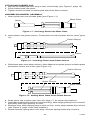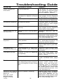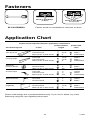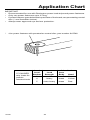
1
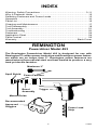
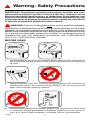
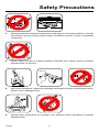
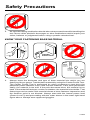
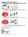
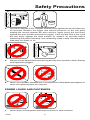
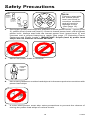
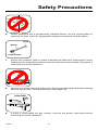
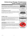
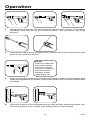
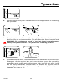
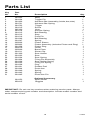
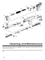
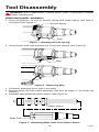
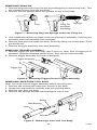
REMINGTON
®
Powerdriver
NDENT LAB
OR
PE
DE
ST
®
I
FO
R P U B LI C
G 028
™
Y
TE
NG
FE
T
AN
Y
OR
AT
IN
Model 493
SA
POWDER ACTUATED TOOL
MANUFACTURERS´ INSTITUTE INC.
G 029
Operating
Instructions
Important:
Read this manual and all labels carefully before operating your powder
actuated tool. This manual should always accompany the tool and be
transferred with it upon change of ownership.
INDEX
Warning: Safety Precautions ............................................................. 3-11
Why A Fastener Holds ......................................................................... 12
Selecting Fasteners and Power Loads ................................................ 13
Operation ............................................................................................. 14
Parts List .............................................................................................. 16
Cleaning and Maintenance .................................................................. 17
Tool Disassembly ................................................................................. 18
Tool Assembly ...................................................................................... 21
Troubleshooting ................................................................................... 23
Fasteners ............................................................................................. 24
Application Chart .................................................................................. 24
Parts Central ........................................................................................ 26
Warranty ................................................................................. Back Cover
REMINGTON
Powerdriver Model 493
The Remington Powerdriver Model 493 is designed for use with
Remington 27 caliber power load strips and Remington power fasteners which are no longer than 3". Remington power fasteners are
manufactured from special steel and heat treated to produce a very
hard yet ductile fastener.
Maximum 3"
Spall Shield
Power Fastener
Barrel
Assembly
Trigger
Muzzle/Guide
Recommended
Approved
Goggles
Power Load
Strip
2
103500
Warning: Safety Precautions
IMPORTANT: Read these operating instructions carefully and completely before trying to operate or service this tool. Improper use of
this tool can cause serious injury or death from firing fastener into
body or from flying debris. We expressly disclaim any liability for any
injury to persons or damage to property which result from your failure
to take the precautions contained in this manual.
WARNING: This tool is designed only for use by qualified operators.
Qualification is obtained through a thorough understanding of the Safety
Warnings and operating instructions as defined in this operating manual.
NOTE: Your local labor regulations may require that the operator of this tool
on a job site be thoroughly trained and certified for competence prior to
operating this tool. For certification procedures, call: 1-800-626-2237
(U.S.A.) or 1-905-826-8010 (Canada).
BEFORE USING
?
1.
?
Always handle the tool as if it were loaded. Before starting work, check that the
tool is unloaded and the muzzle is clear. Never load a tool unless it is going to
be used.
DEF
ECT
IVE
2.
Always inspect to make sure the tool is working properly. If the tool does not
work properly, remove from service and tag “DEFECTIVE.” Do not use the tool
again until it has been properly repaired.
3.
Operators and bystanders must wear goggles and ear protection which meet
or exceed the accepted standards for adequate protection in your country. In
the U.S.A., refer to ANSI standards. In Canada, refer to CSA standards.
103500
3
Safety Precautions
WARNING
POWDER
ACTUATED
TOOLS
IN USE
!
482-10
4.
Always clear the work area on all sides and post appropriate warning signs on
job sites.
482-12
5.
Make sure the work area is clean from loose material and debris.
HANDLING THE TOOL
1.
Never place your hand over the muzzle. Accidental discharge can cause
serious injury.
2.
Never place your finger on the trigger until the tool’s muzzle is against the work
surface.
4
103500
Safety Precautions
POWD
LOAD POWDER
LOADS
3.
Store powder actuated tool and power load strips in a locked container. Unload
tool before storing. Keep power loads of different power levels in separate
containers.
4.
Never carry or pass a loaded powder actuated tool. Never point a powder
actuated tool at anyone.
5.
If the tool is dropped, inspect for damage and repair it before continuing to work.
Never use a damaged tool.
6.
Always take precaution to maintain your balance while operating a powder
actuated tool.
103500
5
Safety Precautions
?
?
?
7.
An operator taking medication should take extra precautions while handling the
tool. Never drink alcoholic beverages or take medications which impair your
vision, balance or judgement before using a powder actuated tool.
KNOW YOUR FASTENING BASE MATERIAL
?
Sinks in
with
average
hammer
blow
?
?
?
CENTER
PUNCH TEST
TOO SOFT
482-28
482-27
482-26
Start
Point
flattens
GREEN
POWER
LEVEL 3
Surface
shatters
YELLOW
POWER
LEVEL 4
TOO HARD
1.
482-29
TOO BRITTLE
482-30
RED
POWER
LEVEL 5
Always know the thickness and type of base material into which you are
fastening. Never guess. Test the base material by using the Center Punch Test.
The Center Punch Test is performed by using a hammer to test drive the
particular power fastener to be used into the material. If the point penetrates
easily, the material is too soft. If the point becomes blunt, the material is too
hard. If the material fractures, cracks or shatters, the material is too brittle. Test
fastenings can be made if the material shows a clear fastener impression and
the fastener point is not blunted. Always start with the lowest power load
(Green-Level 3) and proceeding with the order shown in the lower right-hand
figure above. Always wear approved goggles.
6
103500
Safety Precautions
CAST IRON
GLASS
TILE
BRICK
2.
Never attempt to drive power fasteners into very hard or brittle materials
including, but not limited to cast iron, glass, tile, stone, brick, or hardened steel.
Materials of this type tend to shatter and create hazard from flying particles.
3.
Never make fastenings in spalled or cracked areas.
4.
Never drive power fasteners into thin or easily penetrated materials unless it is
backed by concrete or steel. When in doubt, such as when base material is
concealed, conduct a Center Punch Test (See page 6). Check continually to
avoid fastening into unsuitable material, especially in older buildings.
5.
Do not fasten through or within 1/2" of predrilled or pre-punched holes.
103500
7
Safety Precautions
3"
3"
3"
3"
1X
3X
482-39
482-38
6.
Do not drive power fasteners into concrete less than three times as thick as the
intended fastener penetration, within 3" of the edge, within 3" of another power
fastener or within 3" of a failed power fastener.
WELD
1"
1/2"
482-40
7.
TOO THIN
3/16" MIN
Do not drive power fasteners into steel base material less then 3/16" thick,
within 2" of a weld, within 1/2" of the edge or within 1" of another power fastener.
NO
8.
482-41
YES
When fastening into masonry walls, always drive into horizontal mortar joints,
never into vertical mortar joints. Be careful. A poorly laid joint may permit too
much penetration, and/or unsatisfactory holding power.
OPERATING THE TOOL
90˚
1.
Always hold tool perpendicular to work surface.
8
103500
Safety Precautions
30
WATER
2.
Should the tool fail to fire, hold the muzzle firmly against the work surface for
30 seconds. Release the trigger and remove pressure on the tool while
holding the muzzle against the work surface. Again press the tool firmly
against the work surface and pull the trigger. If the tool still fails to fire, hold
the tool firmly against the work surface for another 30 seconds before
advancing the power load strip. Use remaining loads in strip. Discard power
load strip into water or oil.
Spall
Sheild
3.
Always use the spall shield when driving directly into concrete or steel. Always
wear approved goggles.
GAS
GASOLINE
OLINE
482-50
482-49
4.
Never use a powder actuated tool in an explosive or flammable atmosphere or
when non-sparking tools are required.
POWER LOADS AND FASTENERS
POWD
ER
LOADS
1.
POWDE
LOADSR
Never leave unfired power load strips on floors or work surfaces.
103500
9
Safety Precautions
Start
22
27
CALIBER
GREEN
POWER
LEVEL 3
YELLOW
POWER
LEVEL 4
5
4
3
2
7
1
1
RED
POWER
LEVEL 5
8
9
10
11
12
NICKEL
BRASS
6
482-54
NOTE:
Failure to start with
the lowest power
level can result in
overdrive condition
and will result in
damage to tool
(See page 13).
2.
Remington power load strips are available in three power levels – green (level
3), yellow (level 4) and red (level 5). Green is lowest power level, red is highest
power level. Always start with the lowest power level (green-level 3) and
increase until a proper fastening is made (See page 13 “Selecting Power
Fasteners and Power Loads”). IMPORTANT: Purple (level 6) power load
strips will not function in model 493 tool.
3.
Never use power loads in firearms.
POWDER
POWER
LOADS
LOAD
ONLY
STRIPS
ONLY
482-57
4.
Never carry fasteners or other hard objects in the same pocket or container with
power load strips.
GREEN?
YELLOW?
RED?
5.
A color blind person must take extra precautions to prevent the chance of
mixing the power load strips of various levels.
10
103500
Safety Precautions
482-59
6.
Power fasteners are a permanently installed fixture. An act of demolition is
required for their removal. Appropriate safety precautions must be taken.
Head
Shank
Plastic Flute
482-60
7.
Never use common nails or other materials as fasteners. Remington Power
Fasteners are manufactured from special steel and heat treated to produce a
very hard yet ductile fastener.
8.
Never pry a power load out of the strip. Prying can discharge the load causing
serious injury (See Troubleshooting Guide, page 23).
UNLOAD
1
2
9.
If work is interrupted for any reason, remove the power load strip before
removing the power fastener.
103500
11
Why A Power Fastener Holds
WHY A POWER FASTENER HOLDS
IN CONCRETE
The compression bond of the concrete to the power
fastener accounts for the majority of the holding power.
The fastener displaces the concrete which tries to return
to its original form causing a squeezing effect.
Maximum holding power is achieved when the depth of
penetration produces a bond on the power fastener equal
to the strength of the concrete. As a general rule, penetration should be approximately 1" to 1 1/4" into the base
concrete. Make sure the concrete is at least three times
as thick as the intended fastener penetration. Never have
the power fastener point protrude through the concrete.
NOTE: Concrete needs to cure for 28 days before
maximum fastening holding power will be achieved.
WHY A POWER FASTENER HOLDS IN STEEL
Holding power in steel depends on the elasticity of the
steel. The steel pushes back on the shank of the power
fastener.
Drop a marble into water; the water parts, the marble
continues down, the water closes back. This is similar to
the reaction when a power fastener penetrates steel.
482-65
In steel, the point of the power fastener must penetrate
completely through for highest holding power. If the
fastener does not penetrate, the spring action of the steel
pushes back on the point and tends to force the fastener
out.
Recommended applications are between 3/16-3/8"
steel.
NOTE: When fastening in steel be sure the point goes
through the steel.
12
103500
Selecting Power Fasteners
and Power Loads
FASTENING INTO CONCRETE
The proper power fastener length can be determined by
adding the thickness of the material to be fastened and the
amount of fastener that will actually penetrate the concrete. The concrete must be three times as thick as the
intended fastener penetration. In most cases, penetration
should be approximately 1" to 1 1/4" into the base concrete
material.
482-85
Wood or Non-Metals
To Concrete
FASTENING INTO STEEL
The proper fastener length can be determined by adding
the thickness of the material to be fastened and the
thickness of the steel. The point of the power fastener
must go completely through the steel.
482-79
Wood or Non-Metals
To Steel
POWER LOADS
Always start with the lowest power level (green-level 3). If
the first test fastener does not penetrate to the desired
depth, move to the next highest power level (yellow-level
4). Increase until a proper fastening is made.
IMPORTANT: Damage to the tool will result if the above
instructions are not followed (see illustrations to right and
lower right).
OVERDRIVEN POWER FASTENERS
AND PISTON
An overdriven power fastener results when too strong of
a power load is used causing the piston to extend past the
muzzle. Move to the next lightest power load. Repeated
overdrive will damage your tool. By avoiding overdrive,
you can extend the life of your tool considerably and avoid
costly repairs.
NOTE: Never fire the tool without a power fastener. This
can damage the tool and/or cause possible injury to the
operator.
103500
13
RIGHT
482-66
Flush With Surface
OVERDRIVE
482-67
Piston Extended
Out of Muzzle
Operation
1.
Grasp barrel assembly and slide forward rapidly until it stops. Push barrel
assembly back into tool to the closed position. This sets piston into firing
position.
482-70
2.
482-71
Insert power fastener into muzzle of tool, head end first. Push the fastener until
point is even with end of tool.
NOTE:
Failure to start with
the lowest power
level can result in
overdrive condition
and will result in
damage to tool
(See page 13).
3.
Select the proper power level of power load strips. Always insert powder strip
loads through bottom of handle. Push power load strip in until even with bottom
of handle.
90˚
4.
Place the muzzle of tool perpendicular to work surface without tilting the tool.
Push tool against work surface until sliding action of barrel stops.
14
103500
Operation
5.
Squeeze trigger to set power fastener. Be sure to keep pressure on tool during
this operation.
6.
Grasp base plate and slide barrel forward rapidly until it stops. Push base plate
back into liner to the closed position. This advances the power load strip and
resets the piston for the next fastening.
WARNING: Do not depress muzzle of tool into barrel assembly when
loading new power fastener. Live power load is in firing position.
30
WATER
7.
Should the tool fail to fire, hold the muzzle firmly against the work surface for
30 seconds. Release the trigger and remove pressure on the tool while
holding the muzzle against the work surface. Again press the tool firmly
against the work surface and pull the trigger. If the tool still fails to fire, hold
the tool firmly against the work surface for another 30 seconds before
advancing the power load strip. Use remaining loads in strip. Discard power
load strip into water or oil.
103500
15
Parts List
Key
No.
Part
No.
Description
1
2
3
4
5
6
7
8
9
10
11
12
13
14
15
16
17
18
19
20
21
22
23
24
25
26
27
28
29
30
31
301002
301034
301906
301531
301533
301015
305100
301014
301013
301012
301016
301046
301047
305006
305903
301208
305010
305009
301011
301300
301023
301024
301904
301026
301025
301028
301601
301844
301840
301843
301845
Body
Trigger Pin
Advance Bar Assembly (holder,bar,tube)
Advance Bar Spring
Trigger
Screw
Liner
Annular Spring
Ball Bearing
Stop
Push Pin
Ball Bearing
Spring
Piston Sleeve
Piston Assembly (Includes Piston and Ring)
Piston Ring
Guide
Base Plate
Shear Clip
Sear Holder
Sear
Sear Spring
Firing Pin Assembly
Sear Holder Spring
Firing Pin Spring
Plug
Rubber Pad
Rock Arm
Spring
Spring
Rock Arm Pin
1
1
1
1
1
2
1
1
1
1
1
2
2
1
1
1
1
1
1
1
1
1
1
1
1
1
1
1
1
1
1
301053
056415
Optional Accessory
Spall Shield
Goggles
1
1
Qty.
IMPORTANT: Do not use key numbers when ordering service parts. Always
order components by part number and description. Include model number and
serial number of tool.
16
103500
29
26
31
25
27
30
28
24
23
11
3
20
1
22
4
2
5
21
8
13
10
9
14
12
7
6
16
15
17
18
19
Cleaning and Maintenance
Clean tool after each days use. Disassemble and clean the barrel assembly with the
wire brush provided with tool. Notice: Do not attempt to clean power load strip
channel with wire brush.
Apply good quality penetrating lubricant spray (such as WD-40) sparingly and wipe
dry.
103500
17
Tool Disassembly
WARNING: Never disassemble, replace barrel, clean, or assemble a loaded
powder actuated tool.
REMOVING BARREL ASSEMBLY
1. Using screwdriver, lift end of annular spring and rotate spring until stop is
uncovered (see Figure 1).
Annular Spring
Stop
Figure 1 - Rotating Annular Spring
2. Using thumb, push stop towards rear of tool and remove (see Figure 2).
Stop
Figure 2 - Removing Stop
3. Pull barrel assembly out of liner in tool body.
4. Remove shear clip from barrel assembly (see item 20, page 17, for shear clip
location).
5. Separate base plate from piston sleeve (see Figure 3).
Piston Sleeve
Base Plate
Figure 3 - Separating Base Plate From Piston Sleeve
18
103500
6. Remove piston assembly from piston sleeve (see Figure 4).
Piston Sleeve
Piston
Figure 4 - Removing Piston From Piston Sleeve
7. Tilt rear of base plate down. Guide will slide out.
REMOVING RUBBER PAD
1. Loosen screw on back of rubber pad with 5mm Allen wrench.
2. Detach rubber pad from top of tool first, then pull entire rubber pad from tool.
Rubber Pad
Figure 5 - Removing Rubber Pad
REMOVING ROCK ARM
Rock arm assembly is located on rubber pad.
1. Push out rock arm pin (see Figure 6).
2. Remove rock arm and spring from rubber pad.
Rubber Pad
Rock Arm
Rock
Arm Pin
Spring
Figure 6 - Removing Rock Arm
103500
19
REMOVING FIRING PIN
1. Remove plug from end of tool. Do this by pressing plug in and turning it 90°. This
will release the plug from the tool body.
2. Remove the two springs within the cylinder at rear of tool body.
Plug
Firing Pin
and Sear
Assembly
Springs
Figure 7 - Removing Plug and Springs to Access Firing Pin
3. Use needle-nosed pliers to grasp nut at rear of firing pin assembly. Pull firing pin
assembly and sear assembly from tool body.
4. Remove push pin from inside tool body. Do this by tilting rear of tool down. Push
pin will fall out.
5. Remove firing pin assembly from sear assembly.
REMOVING TRIGGER ASSEMBLY
1. Remove trigger pin from tool body (see Figure 8). Note: End of trigger pin is
threaded. Unscrew threaded portion of pin, then pull pin from tool body.
2. Remove trigger assembly from rear of tool body.
Trigger Assembly
Trigger Pin
Figure 8 - Removing Trigger Pin and Trigger Assembly
REMOVING LINER FROM TOOL BODY
Note: You must remove trigger assembly before removing liner.
1. Remove two screws just under liner at front of tool body.
2. Grasp liner and hold tool vertically with liner pointing down.
3. Remove liner from tool body.
4. Remove two springs and two ball bearings at rear of liner.
Spring
Ball Bearing
Liner
Screws
Figure 9 - Removing Liner From Tool Body
20
103500
Tool Assembly
ATTACHING LINER TO TOOL BODY
1. Replace two ball bearings and springs into end of liner (see Figure 9, page 20).
2. Slide tool body onto liner.
3. Insert two screws into front of tool body just under liner. Tighten screws firmly.
ATTACHING TRIGGER ASSEMBLY TO TOOL BODY
1. Insert trigger assembly into tool body at rear of body (see Figure 8, page 20).
2. Replace trigger pin. Do this by inserting trigger pin through tool body and trigger
assembly. After pin is inserted, tighten pin firmly using a standard screw driver.
ATTACHING FIRING PIN ASSEMBLY
1. Insert push pin into tool body (see item 12, page 17, for push pin location). Hole
for push pin is located in cylinder at rear of tool. The hole for the push pin is located
beside center hole in cylinder. Insert narrow end of pin first.
2. Insert sear assembly into cylinder at rear of tool body. Sear assembly consists of
sear, spring, and sear holder (see items 21, 22, & 23, page 17). Insert sear
assembly sear-end first (see Figure 10). Make sure sear is pointing towards
bottom of tool. Note: Use screw driver to depress sear so sear assembly can pass
into cylinder. Press sear assembly into cylinder until it stops. Note: Sear can be
seen through slot in bottom of cylinder. Use screw driver to depress sear through
slot. Move sear assembly further into cylinder until sear is located at center of slot.
Sear Assembly
Sear
Sear
Slot
Figure 10 - Inserting Sear Assembly Into Cylinder As
Viewed From Bottom Of Tool
3. Insert firing pin (point-first) into sear assembly. Make sure notched side of firing
pin is pointing towards top of tool body. Do not force firing pin assembly into place.
Use screw driver to depress sear through slot in cylinder. With free hand, gently
press firing pin until it drops into place.
4. Place smaller diameter spring into sear assembly. Make sure spring is over top
of firing pin (see Figure 7, page 20).
5. Place large diameter spring over top of smaller spring (see Figure 7, page 20).
6. Place plug over end of both springs.
7. Press plug to tool body. This will compress the springs into the tool body. After
plug enters tool body, turn plug 90° to lock plug.
103500
21
ATTACHING RUBBER PAD
1. Slip top of rubber pad over plug at rear of tool body (see Figure 5, page 19).
2. Press rubber pad into place.
3. Tighten screw on back of rubber pad with 5mm Allen wrench.
ASSEMBLING BARREL ASSEMBLY
1. Insert guide into rear of base plate (see Figure 11).
Base Plate
Guide
Figure 11 - Inserting Guide Into Base Plate
2. Insert piston into piston sleeve. Push piston to end of piston sleeve (see Figure
12).
Piston Sleeve
Piston
Figure 12 - Inserting Piston Into Piston Sleeve
3. Slide base plate onto piston sleeve. Note: Make sure guide groove on base plate
and piston sleeve are in line (see Figure 13).
Piston Sleeve
Guide Groove
Base Plate
Figure 13 - Sliding Base Plate Onto Piston Sleeve
4. Snap shear clip in place (see item 20, page 17, for shear clip location).
5. Insert barrel assembly into liner in tool housing. Note: Align guide groove on barrel
assembly with stop opening on liner.
6. Replace stop. After placing stop in hole on liner, move stop towards front of tool
(see Figure 2, page 18 for stop location).
7. Rotate annular spring back over stop. Annular spring holds stop in place.
22
103500
Troubleshooting Guide
PROBLEM
POSSIBLE CAUSE
REMEDY
Piston hangs out
of muzzle.
Tool overdriven.
Tap piston on hard surface
until piston is pushed back
into the guide. (See “Overdriven Fastener” below)
Piston not properly assembled in relation to barrel
stop.
Remove barrel assembly
(see pages 18-22). Replace
all damaged or missing parts.
Broken piston or piston ring.
Replace piston or piston ring
or take tool to your distributor.
Overdriven fastener. Excessive power.
Change either to next lower
power load or next longer
length fastener.
Piston jammed.
Overdriving of fastener (see
above).
Remove barrel assembly
(see pages 18-22). Replace
other parts if damaged.
Power load strip will
not advance.
Advance bar or spring damaged
Replace advance bar or
springs.
Tool dirty.
Clean tool. Notice: Do not
attempt to clean power load
strip channel with wire brush.
You may damage tool.
Piston not returning to full
rear position.
Barrel must be opened to the
full extended position to
properly position piston.
Worn piston ring or broken
piston.
Replace piston and/or piston
ring or take tool to your distributor.
Tool does not
completely depress.
Misassembled or damaged
sear holder and firing pin
parts.
Remove sear holder and
check all parts for correct fit
assembly.
Tool does not fire.
Failure of tool to depress
completely.
See data listed under “Tool
does not completely depress,” above.
Piston not fully reset.
Fully reset piston. See step 1
under OPERATION, page
14.
Dirt buildup on sear holder
not allowing proper penetration of firing pin or worn firing
pin.
Check firing pin mark on
power load. Clean sear
holder, sear and firing pin.
Replace worn or damaged
parts. Notice: Do not attempt
to clean power load strip
channel with wire brush. You
may damage tool.
Reduction or loss
of power.
Tool does not fire.
Opening and closing Lack of proper cleaning.
of barrel or pushing
down on
tool, etc. is not
smooth but is
rough or binds.
103500
23
Inspect and clean complete
tool. Replace worn or damaged parts. Notice: Do not
attempt to clean power load
strip channel with wire brush.
You may damage tool.
Fasteners
482-79
482-78
SP FASTENERS
482-80
Wood or Non-Metals
To Steel
Wood or Non-Metals
To Concrete
Fasten wood or nonmetals to concrete or steel.
Application Chart
Power load and power fastener application information.
For fastening this
power fastener
length
to this
power load
color
Two by fours
Concrete
Cement block
Steel (3/16" to 3/8" thick)
2 1/2"
2 1/2"
2"
Yellow
Green
Yellow/Red
Furring strips
Concrete
Cement block
Steel (3/16" to 3/8" thick)
1 1/2"
1 1/2"
2"
Yellow
Green
Yellow/Red
Electrical
junction boxes
Concrete
Cement block
Steel (3/16" to 3/8" thick)
1"
1"
3/4"
Yellow
Green
Yellow/Red
Concrete
Cement block
Steel (3/16" to 3/8" thick)
1"
1"
3/4"
Yellow
Green
Yellow/Red
Shelf brackets
Concrete
Cement block
1"
1"
Yellow
Green
1/4" Plywood or
pegboard
Concrete
Cement block
Steel (3/16" to 3/8" thick)
1 1/4"
1 1/4"
1"
Yellow
Green
Yellow/Red
Conduit clips
Power load listings are recommendations only. If you are in doubt,482-81a
try a test
fastening using the next lightest power load.
24
103500
Application Chart
IMPORTANT
• Recommended for use with Remington power load strips and power fasteners.
• Only use power fasteners up to 3" long.
• If power fastener goes below the top surface of the board, use penetrating control
disc (* see illustration below).
• Always wear approved eye and ear protection.
*
Use power fastener with penetration control disc, part number 015549.
482-90
27 CALIBER
strip loads for
powder
actuated tools
103500
Load
Level
Number
3
4
5
Load
Strength
medium
heavy
extra heavy
25
Color Code
Case
Body
Head
brass
Green
brass
Yellow
brass
Red
Parts Central
Contact authorized dealers of this product. If they can’t supply original replacement part(s), either contact your nearest Parts Central (see below) or call DESA
International’s Parts Department at 1-800-972-7879 for referral information.
In Canada call 1-905-826-8010.
When calling DESA International, have ready
• model number of your tool
• replacement part number
MASTER SERVICE CENTER
1184 Wilson NW
Grand Rapids, MI 49504
US 1-800-446-1446
616-791-4760
Mike Fowler
RAILWAY DISTRIBUTORS
264 Railway Avenue
Campbell, CA 95008
408-866-9266
BALTIMORE ELECTRIC
1348 Dixwell Avenue
Hamden, CT 06574
1-800-397-7553
203-248-7553
Parts Department
MANZO ASSOCIATES
1645 Bustleton Pike
Feasterville, PA 19053
215-364-0480
Parts Department
ALL TOOL & FASTENER
7830 N.W. 72nd Avenue
Miami, FL 33166
305-888-6909
Parts Department
21st CENTURY
RD 2, Box 165
Perkasie, PA 18944
215-795-0400
1-800-325-4828
Parts Department
PRECISION TOOL
431 Commerce Park Drive
Suite 106
Marietta, GA 30060
770-421-0688
Bob Young
BLUEBONNET TOOL
10490 Shady Trail
Suite 104
Dallas, TX 75220
214-358-2363
Ken Perry
PORTABLE HEATER PARTS
342 No. County Road 400 East
Valparaiso, IN 46383
219-462-7441
1-800-362-6951
CLARK SUPPLY
9435 Summerbell
Houston, TX 77074
713-771-0404
Parts Department
FBD
601 Hope Street
Bowling Green, KY 42101
502-796-8406
1-800-654-8534
26
103500
Maintenance Log
Date
103500
Maintenance Performed
27
Limited Warranty Agreement
DESA International warrants the Remington Powerdriver Model 493 against defects
in materials and workmanship for a period of one (1) year from the date of purchase.
If within one (1) year from the purchase date this Powder Actuated Tool fails due to
a defect in material or workmanship, DESA will repair or replace the tool at DESA’s
option. To obtain service under this warranty, contact DESA at the number/address
listed below. You must have the Serial Number, Model Number, date of purchase
and indicate the type of problem being experienced. DESA will send replacement
part(s), repair or replace the tool at DESA’s option. However, this warranty does not
cover failures caused by misusing or abusing the product (for proper use of this
product, read and understand the operating instructions in this owners manual).
Repairs made because of misuse, abuse, negligence or accident will be charged for
at regular repair prices.
This express and limited warranty is the only warranty on this product, and to the full
extent permitted by law there are no other warranties, express or implied, including
warranties of merchantability and/or fitness for a particular purpose which extend
beyond the terms of this express and limited warranty.
To the full extent permitted by law, the liability of DESA for personal injury, property
damage or any other damage whatsoever, including consequential and incidental
damages, arising from the sale or use of this product shall not exceed the purchase
price of this product.
This warranty gives you specific legal rights, and you may also have other rights
which vary from state to state.
For information about this warranty write:
In Canada, contact:
In U.S.A., contact:
DESA Industries
of Canada, Inc.
P.O. Box 90004
2701 Industrial Drive
Bowling Green, KY 42102-9004
502-781-9600
Unit #4
2220 Argentia Road
Mississauga, Ontario
L5N 2K7
905-826-8010
Fax 905-826-8236
For Technical Assistance call
Technical Services Department
1-800-323-5190.
103500-01
REV. A
10/96