1
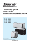
USER'S MANUAL
CLAMP ON MULTIMETER
DCL-420
CIRCUIT-TEST ELECTRONICS
www.circuittest.com
TABLE OF CONTENTS
SAFETY INFORMATION . . . . . . . . . . . . . . . . . . . . . . . . . . . . . . . . . . . . . 2
SAFETY SYMBOLS. . . . . . . . . . . . . . . . . . . . . . . . . . . . . . . . . . . . . . . . . 3
INTRODUCTION . . . . . . . . . . . . . . . . . . . . . . . . . . . . . . . . . . . . . . . . . . . 4
LCD SYMBOL DEFINITIONS . . . . . . . . . . . . . . . . . . . . . . . . . . . . . . . . . 4
FRONT PANEL DESCRIPTION. . . . . . . . . . . . . . . . . . . . . . . . . . . . . . . . 5
SPECIFICATIONS
General . . . . . . . . . . . . . . . . . . . . . . . . . . . . . . . . . . . . . . . . . . . . . . 6
Ranges and Accuracy . . . . . . . . . . . . . . . . . . . . . . . . . . . . . . . . . . . 7
OPERATING INSTRUCTIONS
1. DC Voltage Measurement . . . . . . . . . . . . . . . . . . . . . . . . . . . . . 8
2. AC Voltage Measurement . . . . . . . . . . . . . . . . . . . . . . . . . . . . . 8
3. DC Current Measurement . . . . . . . . . . . . . . . . . . . . . . . . . . . . . 9
4. AC Current Measurement . . . . . . . . . . . . . . . . . . . . . . . . . . 9-10
5. Resistance Measurement . . . . . . . . . . . . . . . . . . . . . . . . . . . . 10
6. Continuity Test . . . . . . . . . . . . . . . . . . . . . . . . . . . . . . . . . . . . . 10
7. Frequency Measurement . . . . . . . . . . . . . . . . . . . . . . . . . . . . 11
8. Temperature Measurement . . . . . . . . . . . . . . . . . . . . . . . . . . . 11
9. Min/Max Measurement . . . . . . . . . . . . . . . . . . . . . . . . . . . .11-12
10. Data Hold Function . . . . . . . . . . . . . . . . . . . . . . . . . . . . . . . . . 12
11. Battery Replacement. . . . . . . . . . . . . . . . . . . . . . . . . . . . . . . . 13
MAINTENANCE . . . . . . . . . . . . . . . . . . . . . . . . . . . . . . . . . . . . . . . . . . . 13
ACCESSORIES . . . . . . . . . . . . . . . . . . . . . . . . . . . . . . . . . . . . . . . . . . . 14
WARRANTY. . . . . . . . . . . . . . . . . . . . . . . . . . . . . . . . . . . . . . . . . . . . . . 14
–1–
SAFETY INFORMATION
This meter is CUL and UL approved and conforms to IEC 61010-1 for Category
II - 600V. This meter is designed to be safe under the following conditions:
indoor use, altitude up to 2000m, temperature 5°C to 40°C, maximum relative
humidity 80% for temperatures up to 31°C decreasing linearly to 50% relative
humidity at 40°C and rated pollution degree 2. Caution and proper guidelines
must be followed for personal and product safety. Read this instruction
manual carefully and completely before using the meter. Lack of caution or
poor safety practices can result in serious injury or death.
• This meter is not recommended for high voltage industrial use; for
example, do not use for measurement on 440VAC or 600VAC industrial
power mains. The unit is intended for use with low energy circuits up to
600VDC / 600VAC or high energy circuits up to 250VAC / 250VDC only.
• Use caution when working above 60VDC or 30VAC RMS as these
voltages pose a shock hazard.
• Always consider circuits to be energized. Never assume any equipment
to be de-energized.
• Always start with power off. Set the function switch to the correct setting
before making any measurements and do not change position of the
function switch during measurements.
• Never connect unit to AC or DC powered circuits when the function
switch is set to resistance, diode check or continuity ranges.
• Always disconnect the power when performing resistance, diode or
capacitance tests. Discharge capacitor before testing.
• Disconnect the live/positive test lead (red) prior to disconnecting the
common/negative test lead (black).
• When BATT appears on the display, change the battery immediately.
• Disconnect test leads from the meter before removing the battery.
• Do not operate the unit unless the case is completely closed.
• When using the test probes always keep fingers behind the finger
guards. Never touch the exposed probe tip.
• Always inspect the instrument, test leads and other accessories for
damage prior to use.
• Use only UL recognized test leads (included with this meter).
–2–
SAFETY SYMBOLS
Safety symbols and special annunciators on the meter and in this manual
indicate cautions and warnings of important operational procedures that must
be followed to ensure personal and product safety.
This symbol indicates a General Warning. When adjacent to a terminal or operating device indicates that the operator must refer to an
explanation in the Operating Instructions.
500V
MAX
This symbol indicates that the terminal(s) so marked must not be connected to a circuit point at which the voltage with respect to ground
exceeds 500V AC/DC.
This symbol adjacent to one or more terminals indicates them as
being associated with ranges that may in normal use, be subjected
to particularly hazardous voltages. For maximum safety, the meter
and its test leads should not be handled when these terminals are
energized.
This meter is protected by double insulation. Service this meter by a
professional only.
–3–
INTRODUCTION
DCL-420 is a True RMS Auto Ranging Clamp on meter with 3-3/4 digit 4000
count display. This meter can measure/test the following:
– Voltage
– Resistance
– Temperature
– Current
– Continuity
– Frequency
LCD DISPLAY SYMBOL DEFINITIONS
DISPLAY/SYMBOL
DEFINITION
DISPLAY/SYMBOL
DEFINITION
AC
Alternating Current
A
Amperage
DC
Direct Current
V
Voltage
Data Hold
°F
Degrees Fahrenheit
Maximum Value
M
Mega
Minimum Value
K
Kilo
MAX
BATT
Low Battery
Ohms
Hz
Continuity
m
milli
–4–
Hertz (Frequency)
1
11
2
12
3
13
4
14
5
CIRCUIT-TEST
6
POWER
ZERO
ADJUST
15
DCL-420
7
AUTO
POWER OFF
TRUE RMS CLAMP METER
8
AC/DC
9
Hz
°F
MIN/MAX
TEMP
V
10
HOLD
A
AC600V
DC600V
!
500V
MAX
!
COM
CAT II
V/F
16
17
18
19
FRONT PANEL DESCRIPTION
NO. ITEM
DESCRIPTION
1
Clamp Jaws
Measure AC and DC current by clamping it around a single current
carrying wire.
2
Centering Marks
Position the conductor within the clamp jaws at the intersection of
these marks in order to meet the specified accuracy.
3
Hand Guard
Provides a protective distance from the jaw
4
DC Amps Zero Adjust
Use to adjust the displayed reading to 0000 in DC Amps mode,
prior to making the measurements
5
Jaw Trigger
Press to open the clamp jaw
6
LCD Display
3-3/4 digit 4000 count LCD Display
7
AC/DC Button
Select AC or DC mode for current and voltage measurements
8
Temperature Jack
Plug in 'K' type thermocouple
9
Voltage Button
Press to select voltage measurement
10
/
Jack
Positive input jack to plug in red test lead to measure resistance or
to check continuity
11 Power Button
Power ON/OFF pushbutton switch
12 Frequency Button
Press to select frequency measurement
13 Temperature °F Button Select temperature measurement function in degrees Fahrenheit
14 MIN/MAX Button
Select MIN or MAX measurement function. This feature will not
work for (°F) temperature function
15 Current Button
Press to select current measurement
16
/
Button
Press to select between resistance measurement or continuity test
17 Data Hold Button
Displayed data will freeze and 'D-H' will appear on the LCD.
Changes in the input signal will not change the display
18 COM Jack
Plug in black test lead in all measurement modes, common ground
19 V/F Jack
Positive input jack to plug in red test lead to measure voltage or
frequency
–5–
SPECIFICATIONS
GENERAL
Display:
Maximum Display:
Ranging:
Auto Shut-off:
Polarity:
3 3/4 digit 4000 count LCD
3999
Auto
Meter will shut-off after 15 minutes from last use
Automatic, minus (-) sign indicates negative polarity, no sign for positive polarity
Input impedance:
10M (DCV / ACV)
Continuity:
Audible signal sounds if resistance is less than 36
(Note: The display will read up to 400.0 in continuity mode)
Over range indication: a) In Continuity Check: 400.0 & appears on
the display with ʻ4ʼ flashing
b) In Resistance Mode: 40.00M appears on the
display with ʻ4ʼ flashing
Operating Temp:
0 to 50° C (32 to 122° F)
Relative Humidity:
<80% Operating/Storage
Power Source:
1 x 9V Battery
Overload Protection: This meter is protected in the Resistance Range by
PTC (Positive Temperature Coefficient) up to 600V
Temperature Probe: 'K' Type Thermocouple rated at 0° to 500°F
(Model no. TL-190)
Dimensions:
90(H) x 232(W) x 45(D) mm
(31/2 x 91/8 x 13/4")
Weight:
390g (13.75 oz)
Accessories included: One pair of test leads, 1 x 9V battery,
ʻKʼ type thermocouple, Screw-on Alligator clips,
Carrying Case, Userʼs manual
–6–
RANGES AND ACCURACY
FUNCTION
RANGE
RESOLUTION
ACCURACY
DC VOLTAGE
(DC V)
400mV
4V
40V
400V
600V
4V
40V
400V
600V
400A
600A
300A
0.1mV
0.001V
0.01V
0.1V
1V
0.001V
0.01V
0.1V
1V
0.1A
1A
0.1A
±(1.0% reading + 4 digits)
600A
1A
400
4k
40k
400k
0 to 500°F
5-100kHz
1000Hz
10KHz
50KHz
0.1
1
10
100
1°F
0.01Hz
0.1Hz
1Hz
10Hz
AC VOLTAGE
(AC V)
DC CURRENT
(DC A)
AC CURRENT
(AC A)
(40-400HZ)
RESISTANCE
TEMP °F
FREQUENCY
±(1.5% reading + 4 digits)
@ 50Hz, 60Hz and 400Hz
±(3.5% reading + 4 digits)
@ 40Hz to 1KHz
±(1.5% reading + 4 digits)
±(1.5% reading + 4 digits)
@ 50Hz, 60Hz and 400Hz
±(3.5% reading + 4 digits)
@ 40Hz to 1KHz
±(1.0% reading + 4 digits)
±(3% reading + 4 digits)
±(1.0% reading + 4 digits)
NOTE: Accuracy consists of: (% reading i.e. accuracy of the measurement circuit +
digits i.e. accuracy of the analog to digital converter)
–7–
OPERATING INSTRUCTIONS
1. DC VOLTAGE MEASUREMENT
WARNING: MAXIMUM INPUT IS 600V DC.
➔ Plug the red test lead into V/F jack and the black test lead into COM
jack.
➔ Press the Power button.
➔ ʻ400.0ʼ,
and
and will appear on the display with the digit ʻ4ʼ flashing.
➔ Press V pushbutton once, ʻACʼ and ʻVʼ will appear on the display.
➔ Press AC/DC pushbutton once, ʻDCʼ and ʻVʼ will now appear on the
display.
➔ Apply the test leads to the circuit to be measured. Ensure that the black
lead is connected to the negative side of the circuit and the red lead to
the positive.
➔ Read the displayed voltage.
➔ If minus (-) sign appears the voltage is negative at the point being
measured.
2. AC VOLTAGE MEASUREMENT
WARNING: MAXIMUM INPUT IS 600VAC (RMS).
➔ Plug the red test lead into V/F jack and the black test lead into COM
jack.
➔ Press the Power button.
➔ ʻ400.0ʼ,
and
and will appear on the display with the digit ʻ4ʼ flashing.
➔ Press V pushbutton once, ʻACʼ and ʻVʼ will appear on the display.
➔ Apply the test leads to the circuit to be measured.
➔ Read the displayed voltage.
–8–
3. DC CURRENT MEASUREMENT
WARNING: DO NOT BREAK OR OPEN THE DC LINE BEING MEASURED. WHEN
MEASURING DC CURRENT THIS UNIT IS DESIGNED TO CLAMP AROUND ONE OF THE DC
LINES. DO NOT ATTEMPT TO MEASURE CURRENT USING THE TEST LEADS. DO NOT PUT
MORE THAN ONE WIRE INSIDE THE CLAMP JAW. DISCONNECT THE TEST LEADS BEFORE
TAKING ANY MEASUREMENTS.
➔ Turn off power to the DC line being measured.
➔ Press the Power button on the clamp meter.
➔ Press A pushbutton once. ʻACʼ and ʻAʼ will appear on the display.
➔ Press AC/DC pushbutton once, ʻDCʼ and ʻAʼ will now appear on the
display.
➔ If the display indicates reading other than ʻ0000ʼ, use a small screwdriver and adjust the Zero Adjust control until the display reads ʻ0000ʼ.
➔ Press the trigger to open the clamp jaws and close around one insulated conductor of the DC line being measured. Ensure that the jaws
are completely closed and do not make any contact with the DC line.
For maximum accuracy it is recommended that the conductor passes
through the centre of the clamp head opening (use the centering marks
on the jaws as a guide).
➔ Now apply power to the DC line being measured.
➔ Read the displayed current indicated with proper decimal point and
symbols.
➔ Open clamp jaws and release.
4. AC CURRENT MEASUREMENT
WARNING: DO NOT BREAK OR OPEN THE AC LINE BEING MEASURED. WHEN
MEASURING AC CURRENT THIS UNIT IS DESIGNED TO CLAMP AROUND ONE OF THE AC
LINES. DO NOT ATTEMPT TO MEASURE CURRENT USING THE TEST LEADS. DO NOT PUT
MORE THAN ONE WIRE INSIDE THE CLAMP JAW. DISCONNECT THE TEST LEADS BEFORE
TAKING ANY MEASUREMENTS.
➔ Turn off power to the AC line being measured.
➔ Press the Power button on the clamp meter.
➔ Press A pushbutton once. ʻACʼ and ʻAʼ will appear on the display.
➔ Press the trigger to open the clamp jaws and close around one insulated conductor of the AC line being measured. Ensure that the jaws
are completely closed and do not make any contact with the AC line.
–9–
For maximum accuracy it is recommended that the conductor passes
through the centre of the clamp head opening (use the centering marks
on the jaws as a guide).
➔ Apply power to the AC line being measured.
➔ Read the displayed current indicated with proper decimal point and
symbols.
➔ Open clamp jaws and release.
5. RESISTANCE MEASUREMENT
WARNING: REMOVE ALL POWER FROM CIRCUIT BEING TESTED WHEN CHECKING
RESISTANCE. DISCHARGE ANY CHARGED CAPACITORS. NEVER CONNECT THE PROBES
TO ANY VOLTAGE WHILE THE FUNCTION IS SET TO / .
➔ Plug the red test lead into /
jack.
jack and the black test lead into COM
➔ Press the Power button.
➔ ʻ400.0ʼ,
➔ Press
and
/
and will appear on the display with the digit ʻ4ʼ flashing.
pushbutton once, M will now appear on the display.
➔ Apply the test leads to the circuit to be measured.
➔ Read the displayed resistance with proper decimal point and symbols
( or K or M ).
6. CONTINUITY TEST
WARNING: REMOVE ALL POWER FROM CIRCUIT BEING TESTED WHEN CHECKING
CONTINUITY. DISCHARGE ANY CHARGED CAPACITORS. NEVER CONNECT THE PROBES TO
ANY VOLTAGE WHILE THE FUNCTION IS SET TO / .
➔ Plug the red test lead into /
jack.
jack and the black test lead into COM
➔ Press the Power button.
➔ ʻ400.0ʼ,
and
and will appear on the display with the digit ʻ4ʼ flashing.
➔ Touch the test probe tips to the circuit or wire you wish to check.
➔ If the resistance is less than 36 , the audible signal will sound. The display
will also show the actual resistance in ohms with proper decimal point.
NOTE: The display will read up to a maximum of 400 ohms in Continuity mode.
– 10 –
7. FREQUENCY MEASUREMENT
NOTE: The meter will read frequency of voltages from 10V to 600V.
➔ Plug the red test lead into V/F jack and the black test lead into COM
jack.
➔ Press the Power button.
➔ ʻ400.0ʼ,
and
and will appear on the display with the digit ʻ4ʼ flashing.
➔ Press Hz pushbutton once, ʻHzʼ will now appear on the display.
➔ Apply the test leads to the point of measurement.
➔ Read the displayed frequency with proper decimal point and symbols
(Hz or KHz).
8. TEMPERATURE MEASUREMENT
WARNING: DO NOT MEASURE TEMPERATURE OF METAL PARTS WITH VOLTAGE
PRESENT ON THEM. REMOVE ALL VOLTAGE SOURCES FROM THE CIRCUIT TO BE TESTED
BEFORE TAKING A TEMPERATURE MEASUREMENT. DISCONNECT THE TEST LEADS BEFORE
TAKING ANY MEASUREMENTS.
➔ Insert the temperature probe into TEMP socket, making sure to observe
the correct polarity.
➔ Press the Power button.
➔ ʻ400.0ʼ,
and
and will appear on the display with the digit ʻ4ʼ flashing.
➔ Press °F pushbutton once and ʻ°Fʼ will appear on the display.
➔ Touch the probe to the component you are testing and keep it there for
about 30 seconds or until the reading stabilizes.
➔ The digital reading will indicate the proper value with decimal point.
9. MIN/MAX MEASUREMENT
NOTE: When MIN/MAX button is pressed to go in to MIN or MAX mode, the autoranging feature is cancelled and the meter will stay in the range it was last in when the
MIN/MAX button was pressed. If a measurement being taken exceeds this range, the
meter will display the maximum range with the far left digit flashing.
NOTE: The MIN/MAX mode will not work for temperature measurements.
➔ Depending on the type of measurement required, follow the instructions
for inserting the test leads and function selection.
– 11 –
➔ Apply the test probes to the component or clamp jaws around the wire
whose variable is to be measured.
a) For MIN value measurement:
➔ Press MIN/MAX pushbutton once, ʻMINʼ and ʻD-Hʼ will appear on the
display. As the value changes, the meter will show the lowest value
measured.
b) For MAX value measurement:
➔ Press MIN/MAX pushbutton twice, ʻMAXʼ and ʻD-Hʼ will appear on the
display. As the value changes, the meter will show the highest value
measured.
NOTE: When using MIN/MAX measurement, if the test leads are moved to test another component, the value may or may not change depending upon the range the meter was last in.
The meter must be turned OFF and the entire procedure must be re-applied.
CAUTION: To cancel MIN/MAX measurement, the meter must be turned OFF. Using
MIN/MAX pushbutton will only cancel this feature, but will not restore the meter’s
autoranging feature.
10. DATA HOLD
This function is used to hold a reading. When this pushbutton is pressed,
the data being displayed at the time will be frozen and ʻD-Hʼ will appear on
the display. Changes in the input signals will not change the display. The
value will show on the display until cancelled. This function can be used in
all measurement modes. Press the pushbutton again to release this function
and ʻD-Hʼ will disappear.
– 12 –
11. BATTERY REPLACEMENT
WARNING: DISCONNECT BOTH TEST LEADS FROM ANY SOURCE OF VOLTAGE
BEFORE REMOVING THE BACK COVER. DO NOT OPERATE THE METER UNTIL THE BACK
COVER IS IN PLACE AND FASTENED SECURELY.
BATT will appear in the display when the battery drops below the operating
voltage and requires replacing.
➔ Turn off the meter and disconnect both test leads.
➔ Remove the single screw securing the battery cover and lift to open.
➔ Replace the 9V battery observing the correct polarity.
➔ Replace the cover and tighten the screw.
MAINTENANCE
a) Always keep the meter dry.
b) Keep the meter clean. Wipe the case occasionally with a damp cloth.
Do not use chemicals, cleaning solvents or detergents.
c) Use and store the meter in recommended normal environmental
conditions. Extreme temperatures can shorten the life of the electronic
components.
d) Use only fresh batteries.
e) Remove the battery when the meter is not being used for a long period
of time.
– 13 –
ACCESSORIES
Test Leads (TL-108)
ʻKʼ Type thermocouple (TL-190)
Screw-on Alligator Clips (TL-210)
Battery: 1 x 9V
Carrying Case
LIMITED WARRANTY
Circuit-Test Electronics warrants to the original purchaser that this product
be free of defect in material or workmanship for a period of 2 years from the
date of purchase. Visit our website (www.circuittest.com) for information on
warranty service.
Any product which has been subjected to misuse or accidental damage is
excluded from the warranty. Except as stated above, Circuit-Test Electronics
makes no promises or warranties either expressed or implied including warranties of merchantability or the fitness for any particular purpose.
Register your product online at www.circuittest.com
CIRCUIT-TEST
ELECTRONICS
A division of R.P. Electronic Components Ltd.
www.circuittest.com
– 14 –
DCL-420_MAN_EN_V3